Shundaiwa DGA20EM User manual
OWNER’S AND OPERATOR’S MANUAL
Vertical, Water-Cooled 4-Cycle Diesel Engine
DGA20EM
X753-008 33 0
X753801-490 0
CAUTION
Do not operate the Generator, or any other appliance, before you have read and understood
the instructions for use and keep near for ready use.


Introduction
Thank you for purchasing this Shindaiwa soundproof diesel engine generator.
This manual has been created to ensure safe usage of this generator. Be sure to read this manual
before operation. Improper operation/handling of this generator will result in an accident or
malfunction.
Handling/Operation of this generator can only be performed by persons who understand the
contents of this manual and can handle/operate the generator in a safe manner. Persons who
suffer from an illness, are taking medicine or not feeling way such that safe operation would be
negatively affected must not operate this generator.
Work performed using this generator and handling/operation of this generator must be in
accordance with corresponding laws and regulations based on such laws. Consult with the
authorized distributor where this generator was purchased if you have any inquiries regarding the
corresponding laws.
Always be sure to include this manual when loaning out this generator and instruct operating
personnel to read this manual before operation.
Store this manual in a specified location where it will be secure and available for consulting at any
time. Order another copy from the authorized distributor where this generator was purchased if this
manual becomes dusty, grimy or torn.
Consult with the authorized distributor where this generator was purchased if you have any
inquiries regarding any points related to this generator and manual.
When inquiring about this generator, be sure to provide the model name and serial number.
If disposing of this generator, do so in a manner that is in compliance with laws related to industrial
waste. Contact the authorized distributor where the generator was purchased if you have any
inquiries regarding proper disposal.
Caution notice ranks in this manual are classified as follows.
WARNING : Indicates a potentially hazardous situation which, if not
avoided, can result in death or serious injury
CAUTION : Indicates a potentially hazardous situation which, if not avoided,
can result in minor or moderate injury and property damage.
< Note > : Other types of cautions and indications.
Note that CAUTION items can also lead to major accidents under some circumstances if not
correctly followed.
All caution notices are important. Be sure to follow all of them.

Table of Contents
1. Safety Guidelines··························································································· 1
2. Specifications ······························································································· 5
2-1. Data········································································································ 5
2-2. Ambient Condition······················································································ 6
3. Use ·············································································································· 6
4. Parts ············································································································ 6
4-1. Outer and Main Components········································································ 6
4-2. Operation Panel ························································································ 7
4-3. Output Panel····························································································· 8
5. Equipment ···································································································· 9
5-1. Controller ································································································· 9
5-2. Switches ·································································································11
5-3. Voltage Regulator ·····················································································12
5-4. Fuel Line Changeover Valve (3-Way Valve) ····················································13
6. Transportation & Installation ··········································································14
6-1. How to transport ·······················································································14
6-2. Installation·······························································································15
7. Connecting load ···························································································16
7-1. Select Load Cable·····················································································16
7-2. Connecting Load Cable··············································································17
7-3. ELCB and Grounding·················································································18
8. Initialization and Pre-check ············································································21
8-1. Engine Oil ·······························································································21
8-2. Coolant / Water ························································································22
8-3. Fan Belt··································································································24
8-4. Fuel ·······································································································24
8-5. Fuel, Engine Oil and Coolant Leakage ··························································25
8-6. Battery····································································································26
9. Operation·····································································································27
9-1. Initialization and Preparation ·······································································27
9-2. Procedures during Operation·······································································29
9-3. Stopping ·································································································30
9-4. Protection Functions··················································································31
9-5. Connecting to External Fuel Tank·································································32
10. Check and Maintenance···············································································33
11. Long Term Storage ······················································································40
12. Troubleshooting··························································································41
13. Generator Circuit Diagram············································································45
14. Engine Circuit Diagram················································································46

1
WARNING : EXHAUST GAS POISONING
Do not operate the generator in poorly ventilated areas such as indoors or tunnels, as
the exhaust gas of the engine contains substances that are harmful to human health.
Do not direct exhaust fumes at bystanders or buildings.
WARNING : ELECTRIC SHOCK
Do not operate the equipment with any doors or covers open.
Always turn all the breakers OFF, place the Power Switch in the OFF position and stop
the engine before connecting / disconnecting the load cable to the output terminal or
receptacle.
Close the output terminal cover before operating.
Do not insert a pin, wire or other metal object into the electrical outlet.
Do not touch the generator if the generator or casing or your body becomes wet during
operation.
Do not touch internal electric parts while the generator is operating.
Always turn the Power Switch to the OFF position and stop the engine, then close and
lock OPERATION PANEL DOOR before checking or maintaining the engine or any
equipment.
WARNING : INJURY
Close all doors and lock them during operation.
Do not open the check door when the Power Switch is in the ON position. It will cause
injury by rotating parts such as cooling fans and fan belt.
Always turn the Power Switch to the OFF position and stop the engine, then close and lock
OPERATION PANEL DOOR before checking or maintaining the engine or any equipment.
Always be sure to use Lifting Hook when lifting up the generator. Using other parts
when lifting up the generator could cause the result of falling.
Do not attempt to lift the equipment with any additional weight such as optional fuel
tanks or trailers.
No persons should ever be under a lifted generator.
Always be sure to check that the breakers on load side and switches for any
equipment using the generator are at OFF before turning the breaker to ON. Also be
sure to advise personnel on the load side that power will be turned on or off before
operating the breaker.
Do not modify the equipment and do not operate with parts removed.
CAUTION : EYE/SKIN INJURY
Wear rubber gloves and other protective wear to protect eyes, skin and clothing from
the battery fluid which contains diluted sulfuric acid. If the battery fluid contacts eyes or
skin, wash out immediately with a sufficient amount of clean water. Be sure to receive
medical treatment, especially if the fluid contacts the eyes.
CAUTION : EXPLOSION
Never use or recharge the battery if the fluid level is below the minimum level.
Do not create sparks or bring flame near the battery as it generates flammable gas.
1 Safety Guidelines
2
CAUTION : FIRE
Do not carry flammable items (such as fuel, gas and paint) or items that are highly
combustible near the generator as the muffler, exhaust gas and other parts become
extremely hot.
Position this generator 3 ft. (1 m) or more from walls or other hindrances, and on a
level surface.
Do not connect the generator output to indoor wiring.
This generator uses diesel fuel. Always be sure to stop the engine and not bring flames
close when inspecting fuel or refueling. Wait until the engine has cooled before
performing such procedures.
If fuel spills, always be sure to wipe and drain off spilled fuel.
Do not operate the equipment with liquid accumulated in the spill containment.
If fuel or oil is leaking, repair the leaking location before operating.
Always be sure to wipe up any spilled fuel or oil.
Allow the generator to cool before covering with the protective cover.
Never allow flame to come close to the generator.
Always make sure that the engine is stopped when working on piping.
After working on the piping, check that there is no fuel leakage.
Absolutely never inspect or perform maintenance to the equipment near fire or other
open flame.
CAUTION : ELECTRIC SHOCK
Do not sprinkle water on equipment or used where exposed to rain.
CAUTION : BURNS
Do not touch the engine and surrounding components immediately after stopping the
engine as they are still extremely hot.
Do not open the radiator cap immediately after stopping the engine. Doing so will result
in hot steam gushing out.
Hot steam gushes out from the coolant sub-tank if the generator overheats. Do not
touch the coolant sub-tank.
Always be sure to stop the engine and allow the engine to cool when performing
inspection or maintenance of engine oil. Opening the oil level gauge or oil filler cap
during operation will result in hot oil gushing out.

3
CAUTION : INJURY
Always be sure to use Lifting Hook when lifting up the generator, and slowly lift it
straight up.
Personnel performing lifting work must wear protective gear such as helmets, safety
shoes and gloves.
Position the generator on a level stable surface so that it cannot slide or move in any
manner.
Before starting operation, always be sure to turn off all switches of equipment using the
generator and all breakers to OFF.
Do not move the generator during operation.
Do not operate the generator if it has been modified or any parts have been removed.
Securely fix the equipment with rope or similar item to avoid any unexpected move
when transporting by truck or other vehicle.
CAUTION : PROPERTY DAMAGE
Do not use the equipment for any improper applications. Improper usage can result in
an accident or malfunction.
If using this generator for medical equipment, check before use with the medical
equipment manufacturer, doctor, hospital or similar entity.
Check that the generator output setting, output terminal connection and load power
source are consistent.
Cable burnout can occur due to generated heat if the load current exceeds the
allowable current of the cable.
The voltage drop between cables is large if the cable is excessively long or thin,
resulting in decreased input voltage to equipment using the generator, thereby causing
decreased performance, faulty operation and malfunction.

4
Warning / Caution Label Locations
When warning / caution labels become unreadable or damaged,
place new labels at the appropriate locations as specified in the following figure.
When ordering the labels, use the following part numbers.
1. Injuries······································ (Part no.: X505-004630)
2. Caution (coolant)························ (Part no.: X505-004650)
3. Safety Precaution ······················· (Part no.: X505-004660)
4. Caution (Electric Shock)·············· (Part no.: X505-004640)
5
2-1. Data
Unit DGA20EM
Generator
Generating Method - Rotating Filed, Brushless 3-Phase
Synchronous Generator
Rated Output kVA 20
kW 16
Rated Voltage V 415
Rated Current A 27.8
Rated Frequency Hz 50
Rated Speed min-1 1500
Phase & Wiring - 3-Phase 4-Wire
Power Factor % 80
Insulation Class - F
Exciting Method - Self Excitation(Brushless)
Poles - 4
Engine
Method - Vertical, Water-cooled 4-Cycle, Diesel Engine
Model No. - Isuzu BV-4LE1
Cylinder-bore x stroke
mm 4 - 85 x 96
Continuous Rated
Output kW{PS}
19.1{26}
Speed min-1 1500
Displacement L 2.179
Combustion Method -
Swirl Chambered
Cooling Method - Water-cooling radiator
Lubricating - Trochoid pump, force-feed lubrication
Starting - Starter Motor
Fuel - Diesel
Oil - SAE Class CD or higher
Fuel Tank Capacity L 78
Lubricant Volume L 8.8(including filter 0.4 L)
Coolant Volume L 8.2(including sub-tank 0.9 L)
Starter Motor Cap. V-kW
12-2.0
Alternator Cap. V-A 12-20
Battery - 75D31R
Dimension
Length mm 1440
Width mm 780
Height mm 1140
Dry Weight kg 699
Installed Weight kg 789
2 Specifications

6
Engine Check Door Radiator Lug for rope Alternator
check
door
2-2. Ambient Condition
Be sure to use the equipment under the following ambient condition range. Otherwise
the condition may cause damage, insufficient output or durability shortage to the
equipment.
■Ambient: Temperature: from -15 to 40 degree Celsius
■Relative: Humidity: less than 80%
■Altitude: Less than 300m
Power Supply for submersible Pump, etc.
Power Supply for lightings, etc.
Power Supply for electric tools, home appliances
4-1. Outer and Main Components
3 Use
4 Parts (Components)
Lug for rope
Lifting Lug
Operation Panel Door
Output Terminal Cover
Fuel Inlet
Engine Check Door
Outer Fuel Outlet
Coolant Drain
Lug for Rope
Oil Drain Plug
Alternator Check Door
Sub Tank
Fuel Tank
Fuel Drain
Water Separator
Fuel Filter
Oil Gage
Outer Fuel Inlet
Oil Filter
Battery
Air Cleaner
Oil Filler
7
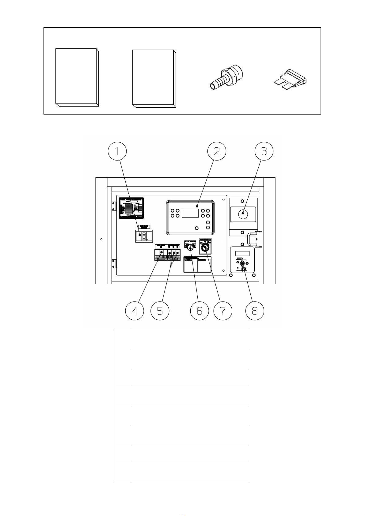
4-2. Operation Panel
1
Main Circuit Breaker
2
Controller
3
Emergency Stop Button
4
3-Phase Breaker
5
1-Phase Breaker
6
Voltage Regulator
7
Power Switch / Air Bleeding
8
Battery Isolator
Accessories
Nipple (2 pieces) Fuse (2 pieces)
Owner’s
Manual
User’s
Manual
For Engine

8
4-3. Output Panel (Side Door)
3-Phase ELCB
1-Phase ELCB
1-Phase
Receptacle
(15A)
3-Phase Receptacle
(20A)
Bonnet Grounding Terminal
Output Terminal Cover

9
5-1. Controller
This generator has a Controller which is used for starting or stopping the power generator
or the engine, for monitoring. If you turn the Power Switch to ON position, the status
Screen appears.
(1) Front panel elements
①STOP button
Press this button to initiate the stop sequence of the gen-set.
② START button
Press this button to initiate the start sequence of the engine.
③LEFT button
Use this button to move left or to change the mode. The button can change the mode
only if the main screen with the indicator of currently selected mode is displayed.
④RIGHT button
Use this button to move right or to change the mode. The button can change the mode
only if the main screen with the indicator of currently selected mode is displayed.
15
5 Equipment
1
2
3
4
5
6
7
8
9
10
11
12
13
14

10
⑤HORN RESET button
Use this button deactivate the horn output without acknowledging the alarms.
⑥FAULT RESET button
Use this button to acknowledge alarms and deactivate the horn output. Inactive alarm
will disappear immediately and status of active alarms will be changed to “confirmed”
so they will disappear as soon as their reasons dismiss.
⑦UP button
Use this button to move up or increase value.
⑧PAGE button
Use this button to switch over display pages.
⑨DOWN button
Use this button to move down or decrease value.
⑩ENTER button
Use this button to finish editing a setpoint or moving right in the history page.
⑪GCB button
No use.
⑫GENERATOR status indicator
There are two states – Gen-set OK (indicator is green) and Gen-set failure (indicator is
red). Green LED is on if the generator voltage is present and within limits. Red LED
starts flashing when gen-set failure occurs. After FAULT RESET button is pressed,
goes to steady light (if an alarm is still active) or is off (if no alarm is active).
⑬GCB on
No use.
⑭Load
No use.
⑮Operation Display
< Note>
The displayed information is structured into “pages” and “screens”. USE PAGE button to switch
over the pages.

11
3P Breaker 1P Breaker
5-2. Switches
(1)
Power Switch / Air Bleeding
This is the main Power Switch of the generator.
When the Power Switch turned to OFF position, the Controller is OFF.
When the Power Switch turned to AIR BLEEDING position,
automatically starts air-bleeding device.
(2) Emergency Stop Button
This button is used to stop the engine in emergency.
By inserting the button, the engine stops.
Be sure to restore the Power Switch to OFF and re-set
the button, turning clockwise after using the emergency stop button.
(3) Main Circuit Breaker
By turning this circuit breaker on the control panel to ON,
Power will be transferred to the output receptacles and to the
load side.
The breaker trips to OFF, either overload or short-circuit.
< Note >
Do not use ELCB as the ON/OFF switch to the load.
(4) 3-Phase Circuit Breaker
1-Phase Circuit Breaker
Each receptacle, 3-Phase and 1-Phase is
incorporated with circuit breaker respectively.
The breaker trips on overload or short-circuit on
to stop power transmission to load.
< Note >
Do not use this breaker as the ON/OFF switch to the load.

12
3P ELCB
(5) 3-Phase Earth Leakage Circuit Breaker (3P ELCB)
1-Phase Earth Leakage Circuit Breaker (1P ELCB)
Each receptacle, 3-Phase and 1-Phase is
incorporated with ELCB respectively.
When current leak occurs, it trips to stop
power transmission to load.
< Note >
Do not use this breaker as the ON/OFF switch to the load
(6) Battery Isolator
When turning the switch to OFF, the engine
electric circuit does not activate due to no
battery power.
5-3. Voltage Regulator
(1) Voltage Regulator
The dial adjusts generator output voltage.
By turning the dial clockwise, you can increase the voltage.
By turning the dial counter-clockwise, you can decrease the voltage.
OFF position ON position
1P ELCB

13
A side Lever Position
3-way Valve
B side Lever Position
5-4. Fuel Line Changeover Valve (3-way valve)
By switching the 3-way valve, you can use fuel from external fuel tank.
In this case, the built-in tank fuel cannot be used.
(1) Using fuel from built-in fuel tank
The lever for 3-way valve is set to
Awhen the equipment is shipped.
Outer fuel inlet and return are
closed with plugs (PT1/2).
Use fuel as they are.
< Note >
After having used the outer fuel and removed piping, be sure to set the lever to A position and
fix the plugs.
(2) Using fuel from external fuel tank
Connect hoses from the external fuel tank to the external fuel intake and the external fuel return
ports, and set the lever for 3-way valve to Bposition.
You can now supply the fuel from
the external gas tank.
For detailed instructions, refer to
『9-5.Connecting to External Fuel Tank』
CAUTION : Fire
Always stop the engine when performing any work on the fuel line.
Always wipe any drip of Diesel fuel or engine oil. Do not use this equipment,
when a leak is found. Repair the equipment before use.
Be sure to confirm that there is no leakage in the piping.
External Fuel Inlet
External Fuel Return
3-way Valve

14
Roping Lug
6-1. How to transport
WARNING : Injuries
When lifting the equipment, always use a lift hook.
Never use roping lug for lifting the unit, for it may cause equipment to drop.
(1) Lifting the equipment
Always use a Lift lug, when lifting
the equipment for transportation.
(2) Transporting the equipment
When transporting the equipment, make
sure that the equipment is secured properly
with ropes tied to the roping lugs through.
< Note >
Always use extreme care when loading, unloading, and transporting the equipment,
otherwise damages and malfunction of the equipment may bring.
6 Transportation and installation
Lifting Lug

15
6-2. Installation
WARNING : Suffocation from exhaust gas
Exhaust fumes from the engine contains many elements harmful to humans.
Do not operate this equipment in poorly ventilated area, such as inside a
room or in a tunnel
CAUTION : Suffocation from exhaust gas
Do not point the exhaust fume toward pedestrians or buildings.
CAUTION : Fire
Always operate this equipment on flat surface and, at least 1 meter away
from any objects (wall, box, etc.).
Temperature around muffler and exhaust can get extremely high. Keep
any inflammable items (such as fuel, gas, paint, etc.) away from the
equipment.
Always set the equipment on hard, flat surface.
Keep the equipment at least 1m from a wall or any obstacles, to allow workable
space to access the control panel and opening of the panel door.
< Note >
This equipment must be operated on hard and flat surface. Operating under any
other conditions may result in malfunctions.
Do not block the airflow from radiator vent or muffler exhaust. It may result in reduced
engine performance, overheating, or damage to the electrical parts.
Operating in dusty area or salty air (by the ocean), or any other particulate
environment may result in clogged radiator, which may cause overheating, other
malfunctions and insulation deterioration. Use extreme care, frequent checks and
maintenance.
16
7-1. Select Load Cable
Select the cable with proper gauge, based on its allowable amperage and the distance
between the generator and the machinery to be connected.
CAUTION : Damage to properties
If the load exceeds the allowable amperage, the damage to the cable may
be damaged in overheating.
If the cable is either too long or too small gauge, there will be greater
voltage drop between cables which brings voltage drop to loads. It may
result in reduced performance in the connected loads, malfunction, or
damages.
< Note >
It is recommended to select the proper gauge and length of cable, in
consideration of the maximum 5% marginal drop only for the rated voltage,
between the terminals of loads and generator via the cables.
Expedient Formula: the voltage drop of cables
3-Phase 3-Wire
1 Length (m)
Voltage Drop (V) = × × Current (A) × √3
58 Dia (mm2)
1-Phase 2-Wire
1 Length (m)
Voltage Drop (V) = × × Current (A) ×2
58 Dia (mm2)
7 Connecting Load
Table of contents
Popular Inverter manuals by other brands

Hitachi
Hitachi SJ-LW instruction manual

Mitsubishi Electric
Mitsubishi Electric FREQROL-K Series instruction manual

Robin America
Robin America RGX2900 parts manual

SunSynk
SunSynk SUN-8K-SG04LP3 user manual

EE Systems Group
EE Systems Group eLEDing EE828WAI-2H quick start guide

Nothern Lights
Nothern Lights OM944T Operator's manual


