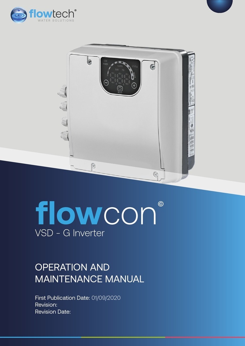
FLOWTECH flowcon VSD H User manual

1
First Publication Date: 01/09/2020
Revision:
Revision Date:
OPERATION AND
MAINTENANCE MANUAL
VSD - H Inverter
flow
con
©

General Information 3
Safety Information 4
Safety Warnings & Precautions 5
Customer / Contractor Responsibilities 6
Protection of the environment 7
Installation 16
Mechanical Installation 17
Electrical Installation 18
Operation 28
Programming 30
Main Menu 32
M40 DIAGNOSTICS 37
M60 SETTINGS 38
M100 BASIC SETTINGS 39
M200 CONF.INVERTER 41
M300 REGULATION 49
M400 SENSOR 51
M500 SEQUENCE CONTR. 53
M700 OUTPUTS 56
M800 REQUIRED VALUES 57
M900 OFFSET 59
M1000 TEST RUN 61
M1100 SETUP 62
M1200 RS-485 INTERFACE 64
M1300 START-UP 66
Maintenance 70
Troubleshooting 71
Technical Reference 73
CONTENTS
OPERATION & MAINTENANCE
2

Definitions of Safety Warnings and
Precautions
WARNING!
Indicates a potentially hazardous situation which, if
not avoided, can result in serious injury or death.
CAUTION!
Indicates a potentially hazardous situation which, if
not avoided. Can result in minor to moderate injury, or
serious damage to the product.
General
Information
These instructions are to assist in the installation of the flowcon VSD - H Inverter please follow
them carefully.
If, having read this Operation & Maintenance Manual, there is any doubt about any aspect of
the installation please don't hesitate to contact our technical team.
flowcon VSD - H Inverter
3

Safety
Information
It is essential that correct and safe working practices are adhered to at all times when installing,
operating and/or maintaining any piece of equipment. Always consult safety data sheets, operating
and maintenance manuals, Health & Safety legislation and recommendations and specific
requirements of any equipment manufacturer, site controller, building manager or any other persons
or organisation relating to the procurement, installation, operation and/or maintenance of any piece
of equipment associated or in conjunction with any product provided by flowech Water Solutions.
This document is intended for ALL installers, operators, users and persons carrying out maintenance
of this equipment and must be kept with the equipment, for the life of the equipment and made
available to all persons at all times. Prior to carrying out any work associated with the set it is essential
that the following sheets are read, fully understood and adhered to at all times.
Equipment must only be installed, operated, used, and/or maintained by a competent person. A
competent person is someone who is technically competent and familiar with all safety practices
and all of the hazards involved.
Any damage caused to any equipment by misapplication, mishandling or misuse could lead to risk of
Electrocution, Burns, Fire, Flooding, death or injury to people and/or damage to property dependent
upon the circumstances involved. flowech Water Solutions accepts no responsibility or liability for
any damage, losses, injury, fatalities or consequences of any kind due to misapplication, mishandling
or misuse of any equipment, or as a result of failure to comply with this manual.
Failure to install, operate, use or maintain the equipment in accordance with the information contained
within this document could cause damage to the equipment and any other equipment subsequently
connected to it, invalidating any warranties provided by flowech Water Solutions to the buyer.
4

Safety Warnings &
Precautions
These instructions should be read and clearly understood before working on the system. Please
read this manual carefully and all of the warning signs aached before installing or operating the
equipment keep this manual handy for your reference. This equipment should be installed, adjusted
and serviced by trained and qualified personnel. Failure to observe this precaution could result in
bodily injury.
WARNING! - Install an emergency stop key separately from the isolator. Rotating
shas can be hazardous.
WARNING! - This equipment has a high leakage current and must be permanently
fixed to earth.
WARNING! - Do not aach or remove wiring or connectors when the power is applied.
Do not check signals during operation. When the power is turned on and the running
command is on, the motor will start rotating. The stop key is only eective when the
function is set. If there is a power failure and an operation instruction is given the unit
may start automatically when the power is reinstated.
WARNING! - Make sure that the input voltage is correct. Be sure to install the unit in
a room that is not exposed to direct sunlight and is well ventilated.
Avoid environments which have a high ambient temperature, high humidity or
excessive condensation. Avoid dust. Corrosive gas, explosive gas, inflammable gas,
grinding-fluid mist and salt damage, etc.
WARNING! - Do not connect the power source to any terminals except power
connectors.
WARNING! - Motor control equipment and electronic controllers are connected to
hazardous line voltages. When servicing drives and electronic controllers, you may be
exposed to components at or above the line potential. Extreme care should he taken
to protect against shock. Dangerous voltage may exist aer the power light is o.
Wait more than 5 minutes aer turning o the power supply before performing
maintenance or inspection. Hazard of electric shock. Disconnect incoming power
before working on this unit.
WARNING! - The inverter should be protected separately against ground fault.
Observe the regional regulations for electrical installation!
flowcon VSD - H Inverter
5

CAUTION! - It is strongly recommended that all electrical equipment conforms
to National Electrical Codes and local regulations. Only qualified personnel should
perform installation, alignment and maintenance. The manufacturer reserves the right
to alter the technical data in order to make improvements or update information.
CAUTION! - Failure to observe these rules will render the guarantee invalid. The same
applies to repair jobs and/or replacement. Your legal rights are not aected.
CAUTION! - The manufacturer declines all responsibility in the event of damage or
injury caused as a result of tampering with the equipment.
CAUTION! - Do not switch on/o power supply to run/stop the motor/system! Start
the unit only by using run buon or external run command.
Customer / Contractor
RESPONSIBILITIES
It is the responsibility of the customer and/or the contractor:
• To ensure that anyone working on the equipment is wearing all necessary protective gear
and/or clothing.
• Is aware of appropriate health & safety warnings.
• Has read the information in this section of the manual.
6

Protection of the environment
Emissions and waste disposal
Observe the local regulations and codes regarding:
Reporting of emissions to the appropriate authorities
Sorting, recycling and disposal of solid or liquid waste
Clean-up of spills
Exceptional Sites – Radiation Hazard
If the product has been exposed to ionizing radiations, implement the necessary safety measures for the
protection of people. Do NOT send the product back if it has been exposed to nuclear radiation.
Recycling guidelines
Always follow local laws and regulations regarding recycling.
Waste and emissions guidelines
Do not dispose of equipment containing electrical components together with domestic waste.
Collect it separately in accordance with local and currently valid legislation.
Product warranty
For information on the warranty refer to the documentation of the sale contract.
Transportation and Storage
Inspect the delivery
Packaging inspection
Check that quantity, descriptions and product codes match the order.
Check the packaging for any damage or missing components.
In case of immediately detectable damage or missing parts:
Accept the goods with reserve, indicating any findings on the transport document, or
Reject the goods, indicating the reason on the transport document.
In both cases, promptly contact Flowtech from whom the product was purchased.
Inspection of the unit
Remove packing materials from the product.
Dispose of all packing materials in accordance with local regulations.
Inspect the product to determine if any parts have been damaged or are missing.
If applicable, unfasten the product by removing any screws, bolts, or straps.
For your personal safety, be careful when you handle nails and straps.
Contact Flowtech if there is any issue.
System Liing
Assembled units and their components are heavy. Failure to properly li and support this equipment can
result in serious physical injury and/or equipment damage. Li equipment only at the specifically identified
liing points. Liing devices such as eyebolts, slings, and spreaders must be rated, selected, and used for the
entire load being lied.
Always li the unit by its designated liing points.
Use suitable liing equipment and ensure that the product is properly harnessed.
Wear personal protective equipment.
Stay clear of cables and suspended loads.
flowcon VSD - H Inverter
7

Liing diagrams
Transportation guidelines
Stay clear of suspended loads.
Observe accident prevention regulations in force.
Do not damage the cables during transport; do not squeeze, bend or drag the cable.
Always keep the cable ends dry.
Secure the unit against tipping over and slipping until it is mounted and fixed in its final location.
Li and handle the product carefully, using suitable liing equipment (stacker, crane, crane mounting device,
liing blocks, sling ropes, etc.).
Always li the unit by its liing handle. Never li the unit by the motor cable or by the hose.
Storage guidelines
Storage location
The product must be stored in a covered and dry location free from heat, dirt, and vibrations.
Protect the product against humidity, heat sources, and mechanical damage.
Do not place heavy weights on the packed product.
Product Description
The images show a typical single-pump and multi-pump system using the unit.
When the system is connected directly to the water supply use a low-pressure switch on the suction side.
1. Pump with Inverter 6. Low water control
2. Diaphragm pressure tank 7. Pressure gauge
3. Distribution panel 8. Pressure sensor
4. Gate valve 9. Drain tap
5. Non-return valve
8

Pressure tank
A diaphragm pressure tank is used on the discharge side of the pump to maintain pressure in the pipes
when there is no water demand. The unit stops the pump from continuing to run at zero demand and reduce
the size of the tank that is required for supply purposes.
The tank must be permied and suitable for systems pressure.
The capacity of the tank must be 10% of the maximum system flow rate of the pump or pumps (0.1 times
the flow rate in l/min or gal/min). Turn o the unit to reduce the water pressure to check and set the correct
pre-charged pressure. The pre-charge pressure of the tank can be determined by using the following table:
Required pressure or Start Value when active [bar]
Pre-charge pressure [bar]
Description
Flowcon H Inverter is a pump-mounted variable speed, microprocessor-based system controller.
It can be mounted onto virtually any model of fan cooled motor and is simple to integrate into BMS systems
with ModBus or Bacnet communication as standard.
In a variable speed controlled system, the pump works every time with the speed where it produces at the
reduced flow exactly the required head. Therefore there is no wasted energy given to the system like on/o
or bypass control.
Intended use
Flowcon H Inverter is made for the following pump applications:
• Pressure, level, and flow regulation
• Closed loop systems
• Irrigation applications with single or multiple pumps
Improper use
The product must not be used for constant torque applications.
Approvals and certifications
The unit complies with UL508C thermal memory retention requirements.
Application
The application alternatives for the product are the following:
• Actuator
• Controller
• Cascade serial / Synchronous
• Cascade relay
Actuator
This mode is used for a unit in a single pump operation only. The unit operates as an actuator according an
external speed signal or continuous operation on either one or two programmed frequencies. This is done by
using the corresponding digital input.
Controller
This mode is set as the default operating mode and is used for a unit in a single pump operation.
Cascade serial / Synchronous
In these applications, each of the pumps (up to eight pumps) must be equipped with a unit.
The units are connected via the RS485 interface and communicate via the provided protocol.
The combination of the dierent units which are used in a multi-pump-system depends on the system
requirements.
flowcon VSD - H Inverter
9

It is possible to run all pumps in cascade serial mode and synchronous mode as well. If one unit fails, then
each pump of the system can become the lead pump and can take control.
Cascade relay
One pump is fied with the unit and up to five slave pumps can be switched to on/o on demand. The unit
uses an additional Premium Card for this purpose.
For switching the slave pumps an external switchboard has to be installed.
Example
The example shows a booster set with four pumps where only one speed-controlled pump and the others
are fixed speed.
Technical Data
Electrical specification
Model
2.015 2.022 2.030 2.040 3.015 3.022 3.030 3.040 3.055 3.075 3.110 4.015 4.022 4.030 4.040 4.055 4.075 4.110 4.150 4.185 4.220
Input
Mains
Supply
Voltage
LN L1 L2 L3 L1 L2 L3
Nominal
input
voltage
208–240±10% 208–240±10% 208–240±10%
Maximum
Input
Current
11.6 15.1 22.3 27.6 7.0 9.1 13.3 16.5 23.5 29.6 43.9 3.9 5.3 7.2 10.1 12.8 16.9 24.2 33.3 38.1 44.7
eciency,
rated [%],
typically:
94.0 93.5 93.5 96.0 96.0 96.0 96.0 96.0 96.0 96.0 96.0 96.5 96.5 96.5 96.5 97.0 97.0 97.0 97.0 97.0 97.0
Output
Output
Voltage 0-240 0-100% of supply voltage 0-100% of supply voltage
Maximum
output
current
continuous
7.5 10 14.3 16.7 7.5 10 14.3 16.7 24.2 31 44 4.1 5.7 7.3 10 13.5 17 24 32 38 44
Output
frequency 15-70
Environmental specification
Storage temperature -30°C [-22°F] to 70°C [158°F]
Relative humidity 5%-95% - Condensation is not permied
10

Operational temperature
-10°C [-14°F] to 55°C [131°F]
100% power rating -10°C [-14°F] to 40°C [104°F]
with de-rating 40°C [104°F] to 55°C [131°F]
Air pollution The air may contain dry dust as found in workshops where
there is excessive dust due to machines. Excessive amounts
of dust, acids, corrosive gases, salts etc. are not permied.
Altitude Max. 1000 m above sea level. For installation over 1000 m
above sea level, the maximum output power has to be de-
rated by 1% for every additional 100 m. If the installation site is
over 2000 m above sea level, please contact Flowtech.
Installation specification
Protection Motor drive input have to be protected by an external circuit
breaker/ fuse
Motor wire type shielded power cable
Maximum motor cable length (no EMC
compliant), screened 50m (164)
Maximum motor cable length (no EMC
compliant), unscreened 100m (328)
EMC compliance
In accordance with IEC 61800-3 and EN 61000 series standards, shield cable will be used for motor drive
output and communication.
Installations must be done according EMC correct installations and avoiding pigtails (on the drive side),
otherwise EMC cannot be guaranteed.
Class of protection
• IP55, Enclosure Type 1
• Protect the product from direct sunlight
• Protect the product from direct rainfall
• Outdoor installation without protection, to especially keep the temperature limits of the product, is not
permied
Motor thermal protection
Motor thermal protection can be implemented using various techniques: PTC sensor in motor windings or
Soware Thermal Control (STC).
Protection against motor overheating comes from par. 290 “STC Motor Protection”, which by default is pre-
se to data value “STC trip”.
The STC function is initialized at 1.125 x rated motor current and rated motor frequency. The STC function
provides class 20 motor overload protection in accordance with the NEC.
Motor thermal protection prevents the motor from overheating. The STC function is an electronic feature that
simulates a bimetal relay that is based on internal measurements.
The characteristic is shown in the following figure.
flowcon VSD - H Inverter
11

The X-axis shows the ratio between Motor actual and Motor nominal. The Y-axis shows the time in seconds
before the STC cuts o and trips the frequency converter. The curves show the characteristic nominal speed,
at twice the nominal speed and at 20% of the nominal speed. The curve shows that at lower speed the STC
cuts o at lower heat due to less cooling of the motor. In that way, the motor is protected from overheating
even at low speed. The STC function calculates the motor temperature that is based on actual current and
speed.
The calculated percentage of allowed maximum temperature is visible as a readout in par. 293 “Motor
Thermal”.
With the STC the motor is protected from being overheated and there is no need for any further motor
protection. That means when the motor is heated up the STC timer controls how long the motor can be
operated at the high temperature before it is stopped in order to prevent overheating.
Motor thermal protection can also be achieved using an external thermistor: set par. 290 “STC Motor
Protection” to data value “Thermistor trip”.
Dimensions and weights
All measurements are in millimetres (inches).
The images are not to scale.
Free distance
Area Models Free Distance
Above the unit All > 300 mm (12 in)
Center-distance between
units (to ensure space for
cabling)
2.015 ÷ 2.022 | 3.015 ÷ 3.022 |
4.015 ÷ 4.040 > 300 mm (12 in)
2.030 ÷ 2.040 | 3.030 ÷ 3.055 |
4.055 ÷ 4.110 > 430 mm (17 in)
3.075 ÷ 3.110 | 4.150 ÷ 4.220 > 550 mm (21,6 in)
12

Dimensional drawings
Figure 4: 2.015, 2.022, 3.015, 3.022, 4.015 ÷ 4.040
Figure 5: 2.030, 2.040, 3.030 ÷ 3.055, 4.055 ÷ 4.110
Figure 6: 3.075 ÷ 3.110, 4.150 ÷ 4.220
Weight
Models Maximum Weight
2.015 ÷ 2.022 | 3.015 ÷ 3.022 | 4.015 ÷ 4.040 5,6 Kg (12,3 lbs)
2.030 ÷ 2.040 | 3.030 ÷ 3.055 | 4.055 ÷ 4.110 10,5 Kg (23 lbs)
3.075 ÷ 3.110 | 4.150 ÷ 4.220 15,6 Kg (34,4 lbs)
flowcon VSD - H Inverter
13

Design and layout
The unit can be fied with the features the application requires.
Position Number Description
1 Power board, heatsink, EMC filter
2 Control board
3Cover
4 Plastic cover
14

Included mounting components
Included
components
Cable outer diameter Model
(mm) inches 2.015 ÷ 2.022
|
3.015 ÷ 3.022
|
4.015 ÷
4.040
2.030 ÷
2.040 |
3.030 ÷
3.055 |
4.055 ÷ 4.110
3.075 ÷ 3.110
|
4.150 ÷
4.220
Cable
Gland(s) and
Lock Nut(s)
M12 3.5 ÷ 7.0 0.138 ÷
0.275
3 3 3
M16 5.0 ÷ 10.0 0.197 ÷
0.394
2 2 2
M20 7.0 ÷ 13.0 0.275 ÷
0.512
2
M25 10.0 ÷ 17.0 0.394 ÷
0.669
2
M32 13.0 ÷ 21.0 0.512 ÷ 0.827 2
M40 19.0 ÷ 28.0 0.748 ÷ 1.102 2
Entry Thread
Reducer
M40 ->
M32
2
Plug(s)
for Cable
Gland(s)
M12 3 3 3
M16 2 2 2
Screws M5x30 4
M5x40 4
M6x40 4 4
M6x50 4 4
Spade
Connector(s)
for PE
conductors
RF-U 4 2 2
BF-U 4 2 2
GF-U 4 2 2
Spares
sealing ring
2
Centering pin 1 1 1
Mounting
Clamps
4 4 4
For 3.075 ÷ 3.110 or 4.150 ÷ 4.220, if the cables outer diameter is incompatible with the included cable glands,
use the supplied Entry Thread Reducers (and spares sealing rings).
flowcon VSD - H Inverter
15

Optional components
Component Description
Motor cables The motor cable that is ready to connect to the unit.
Mounting ring If the motor fan is made of plastic, then a mounting ring is used.
It is available in two diameters: 140 mm (5.5 in) and 155 mm (6.1 in).
Sensors
The following sensors can be used with the unit:
• Pressure-transducer
• Dierential pressure-transducer
• Temperature-sensor
• Flow indicator (orifice plate, inductive flow meter)
• Level-sensor
Premium Card Card to control up to five slave pumps and to connect additional analog and digital
I/Os
Wi-Fi Card To connect and interact wireless with
Installation
Installation site checklist
Never install the system controller in an explosive or flammable environment.
• Always refer to the local and national regulations, legislation, and codes in force regarding selection of
installation site, and water and power connections.
• Keep the manual, drawings, and diagrams accessible for detailed installation and operation instruc-
tions. It is important that the manual is available for equipment operators.
• Install the unit on the motor fan cover. Keep motor cables as short as possible. Check the motor char-
acteristics for actual tolerances.
• For wall mounting installations with long motor cables, use the output filter option to protect the motor.
• Ensure that the ingress protection rating of Inverter (IP55, Type1) is suitable for the installation environ-
ment.
• Ingress protection. IP55 (Type 1) rating can only be guaranteed if the unit is properly closed.
• Make sure that there is no liquid on the unit before opening the plastic cover.
• Ensure all cable glands and unused holes for glands are properly sealed.
• Ensure that the plastic cover is properly closed.
• Device damage through contamination. Do not leave uncovered.
Frequency converter and motor pre-installation check list
Compare the model number of the unit on the nameplate to what was ordered to verify the proper
equipment.
• Ensure each of the following are rated for same voltage:
• Mains (power)
• Frequency converter
• Motor
• Ensure that the frequency converter output current rating is equal to or greater than motor service
factor current for peak motor performance.
• Motor size and frequency converter power must match for proper overload protection.
• If frequency converter rating is less than motor, full motor output cannot be achieved.
16

Mechanical Installation
Cooling
The frequency converter is cooled by means of air circulation. To protect the unit from overheating, it must be
ensured that the ambient temperature does not exceed the maximum temperature stated for the frequency
converter and that the 24-hour average temperature is not exceeded.
• Derating for temperatures between 40°C (104°F) and 50°C (122°F) and elevation 1000m (3300 )
above sea level must be considered.
• Improper mounting can result in overheating and reduced performance.
During the normal operation, the heat sink surfaces may be so hot that only the buons should be touched
to avoid burns.
Liing
• Check the weight of the unit to determine a safe liing method.
• Ensure that the liing device is suitable for the task.
• If necessary, plan for a hoist, crane, or forkli with the appropriate rating to move the unit.
• For liing, use hoist rings on the unit, when provided.
Mounting
Install the unit on the motor fan cover. Keep motor cables as short as possible. Check the motor
characteristics for actual tolerances.
Always use a stainless steel mounting ring if the motors fan cover is made of plastic.
1. Fit the rubber centering pin [6] on the boom
2. Center the unit on the motor fan cover [3] using the centering pin [6].
3. Adjust mounting clamps [5] length for smaller motor sizes, as indicated in the picture that follows.
Take care about sharp edges and remove them properly.
4. Fasten the unit:
a. Fasten the mounting clamps [5] and relative screws [7].
b. Tighten the screws [7] until the two boom teeth in the brackets grip the fan cover.
c. Tighten the screws until the unit is securely fastened.
5. Remove the screws for plastic cover [9].
6. Remove the plastic cover [8].
7. Make the electrical connections.
You can remove the metal plate to make the electrical installation easier.
1. Actual value sensor
2. Motor conduit box
3. Motor fan cover
4. Motor cable
5. Mounting clamps
6. Centring pin
7. Screws for mounting clamps
8. Plastic cover
9. Screws for plastic cover
Refer to callouts in preceding image.
flowcon VSD - H Inverter
17

8. Mount and fasten the plastic cover [8] using 2,0 Nm tightening torque.
Electrical Hazard:
Make sure that all the cable glands are mounted properly and that all the unused cable entries use closing
plugs.
Mounting clamps
Electrical Installation
Precautions
EQUIPMENT HAZARD. Rotating shas and electrical equipment can be hazardous. All electrical work must
conform to national and local electrical codes. Installation, start-up, and maintenance must be performed by
trained and qualified personnel. Failure to follow these guidelines could result in death or serious injury.
Electrical Hazard:
All electrical wiring must be carried out by an authorized electrician, in accordance with the electrical
regulations locally in force.
WIRING ISOLATION. Run input power, motor wiring and control wiring in three separate metallic conduits or
use separated shielded cable for high frequency noise isolation. Failure to isolate power, motor and control
wiring could result in less than optimum frequency converter and associated equipment performance. For
your safety comply with the following requirement: Electronic control equipment is connected to hazardous
mains voltage. Extreme care should be taken to protect against electrical hazards when applying power to
the unit.
Earth (grounding) requirements
For operator safety, it is important to ground the frequency converter properly in accordance with national and
local electrical codes as well as instructions contained within this document. Ground currents are higher than
3.5 mA. Failure to ground the frequency converter properly could result in death or serious injury.
It is the responsibility of the user or certified electrical installer to ensure correct grounding (earthing) of the
equipment in accordance with national and local electrical codes and standards.
• Follow all local and national electrical codes to ground electrical equipment properly.
• Proper protective grounding for equipment with ground currents higher the 3.5 mA must be estab-
lished. See the Leakage current (>3.5 mA) section for details.
• A dedicated ground wire is required for input power, motor power and control wiring.
• Use the clamps provided with the equipment for proper ground connections.
• Do not ground one frequency converter to another in a “daisy chain” fashion.
• Keep the ground wire connections as short as possible.
• Using high-strand wire to reduce electrical noise is recommended.
• Follow motor manufacturer wiring requirements.
Leakage current (>3.5 mA)
Follow national and local codes regarding protective earthing of equipment with a leakage current > 3.5 mA.
Frequency converter technology implies high frequency switching at high power. This will generate a leakage
current in the earth connection. A fault current in the frequency converter at the output power terminals
might contain a DC component which can charge the filter capacitors and cause a transient earth current.
18

The earth leakage current depends on various system configurations including RFI filtering, screened motor
cables, and frequency converter power.
EN/EC61800–5–1 (Power Drive System Product standard) requires special care if the leakage current exceeds
3.5 mA.
Earth grounding must be reinforced in one of the following ways:
• Earth ground wire of at least 8 AWG or 10 mm2 Cu (or 16mm2 Al).
• Two separate earth ground wires of the same cross sectional area.
On the inverter, the phase conductor and the corresponding protective earthing conductor can be of the
same cross-sectional area, provided they are made of the same metal (because the cross-sectional area of
the phase conductor is less than 16 mm2). The cross-sectional area of every protective earthing conductor
which does not form a part of the supply cable or cable enclosure shall, in any case, be not less than:
• 2.5 mm2 if mechanical protection is provided or
• 4 mm2 if mechanical protection is not provided. For cord-connected equipment, provisions shall be
made so that the protective earthing conductor in the cord shall, in the case of failure of the strain-re-
lief mechanism, be the last conductor to be interrupted.
Protection devices
Fuses and Circuit Breakers
• An electronically activated function within the frequency converter provides overload protection in the
motor. The overload calculates the level of increase to activate timing for the trip (controller output
stop) function. The higher the current draw, the quicker the trip response. The overload provides Class
20 motor protection.
• Inverter must be provided with short-circuit and over-current protection to avoid overheating of the
cables in the installation. Input fusing and/or circuit breakers are required to provide this protection.
Fuses and Circuit Breakers must be provided by the installer as part of installations.
• Use recommended fuses and/or circuit breakers on the supply side as protection in case of compo-
nent breakdown inside the adjustable frequency drive (first fault). Use o recommended fuses and
circuit breakers ensures possible damage to the adjustable frequency drive is limited to damages in-
side the unit. For other circuit breaker types, ensure that the energy into the adjustable frequency drive
is equal to or lower than the energy provided by recommended types.
• The fuses below are suitable for use on a circuit capable of delivering 100,000 Ams (symmetrical),
480V maximum. With the proper fusing the adjustable frequency drive Short Circuit Current Rating
(SCCR) is 100,000 Ams.
Table 1: Recommended fuses and circuit breakers
Voltage Supply Model
Fuse Circuit Breaker
UL Non UL
Bussmann Edison Lielfuse Ferraz- Shawmut Fuse ABB
Type T Type gG MCB S200
1~230 VAC
2.015 JJN-20 TJN (20) JLLN 20 A3T20 20 S201-C20
2.022 JJN-25 TJN (25) JLLN 25 A3T25 25 S201-C25
2.030 JJN-35 TJN (35) JLLN 35 A3T35 35 S201-C32
2.040 JJN-35 TJN (35) JLLN 35 A3T35 35 S201-C40
Voltage Supply Model
Fuse Circuit Breaker
UL Non UL
Bussmann Edison Lielfuse Ferraz- Shawmut Fuse ABB
Type T Type gG MCB S200
3~230 VAC
3.015 JJN-15 TJN (15) JLLN 15 A3T15 16 S203-C16
3.022 JJN-15 TJN (15) JLLN 15 A3T15 16 S203-C16
3.030 JJN-20 TJN (20) JLLN 20 A3T20 16 S203-C20
3.040 JJN-25 TJN (25) JLLN 25 A3T25 25 S203-C25
3.055 JJN-30 TJN (30) JLLN 30 A3T30 25 S203-C32
3.075 JJN-50 TJN (50) JLLN 50 A3T50 50 S203-C50
3.110 JJN-60 TJN (60) JLLN 60 A3T60 63 S203-C63
flowcon VSD - H Inverter
19

3~380-
460 VAC
4.015 JJS-10 TJS (10) JLLS 10 A6T10 10 S203-C10
4.022 JJS-10 TJS (10) JLLS 10 A6T10 10 S203-C13
4.030 JJS-15 TJS (15) JLLS 15 A6T15 16 S203-C13
4.040 JJS-15 TJS (15) JLLS 15 A6T15 16 S203-C16
4.055 JJS-20 TJS (20) JLLS 20 A6T20 20 S203-C20
4.075 JJS-20 TJS (20) JLLS 20 A6T20 20 S203-C25
4.110 JJS-30 TJS (30) JLLS 30 A6T30 30 S203-C32
4.150 JJS-50 TJS (50) JLLS 50 A6T50 50 S203-C50
4.185 JJS-50 TJS (50) JLLS 50 A6T50 50 S203-C50
4.220 JJS-60 TJS (60) JLLS 60 A6T60 63 S203-C63
Type gG fuses in the table are reporting the fuses rated current.
Residual Current Devices, RCDs (GFCIs)
Where Ground Fault Circuit Interrupters (GFCIs) and residual current devices (RCDs), also know as earth
leakage circuit breakers (ELCDs), are used, comply with the following:
• For 2.015 ÷ 2.040, use GFCIs (RCDs) which are capable of detecting AC currents and pulsating cur-
rents with DC components. These GFCIs (RCDs) are marked with the following symbol:
• For 3.015 ÷ 3.110 and 4.015 ÷ 4.220, use GFCIs (RCDs) which are capable of detecting AC and DC cur-
rents. These GFCIs (RCDs) are marked with the following symbols:
• Use GFCIs (RCDs) with an inrush delay to prevent faults due to transient earth currents.
• Dimension GFCIs (RCDs) according to the system configuration and environmental considerations.
When an earth leakage circuit breaker or ground fault circuit interrupter is selected, the total leakage current
of all the electrical equipment in the installation must be taken into account.
Wire type and ratings
• All wiring must comply with local and national regulations regarding cross section and ambient tem-
perature requirements.
• Use cables with a minimum heat resistance of +70 °C (158 °F); to obey the UL (Underwriters Labora-
tories) regulations, it is recommended that all power connections be made with a minimum 75°C rat-
ed copper wire of the following types: THW, THWN.
Table 2: Recommended power connections cables
Model Power supply input cable + PE Motor output cables +PE
Wire numbers x Max.
copper section
Wire numbers x
Max. AWG
Wire numbers x Max.
copper section
Wire numbers x
Max. AWG
2.015 3 x 2mm 3 x 14AWG 4 x 2mm 4 x 14AWG
2.022
2.030 3 x 6mm 3 x 10AWG 4 x 6mm 4 x 10AWG
2.040
3.015 4 x 2mm 4 x 14AWG 4 x 2mm 4 x 14AWG
3.022
3.030
4 x 6mm 4 x 10AWG 4 x 6mm 4 x 10AWG
3.040
3.055
3.075 4 x 16mm 4 x 5AWG 4 x 16mm 4 x 5AWG
3.110
4.015
4 x 2mm 4 x 14AWG 4 x 2mm 4 x 14AWG
4.022
4.030
4.040
4.055
4 x 6mm 4 x 10AWG 4 x 6mm 4 x 10AWG
4.075
4.110
4.150
4 x 16mm 4 x 5AWG 4 x 16mm 4 x 5AWG
4.185
4.220
Table 3: Tightening torques for power connections
20
This manual suits for next models
19
Table of contents
Other FLOWTECH Inverter manuals
Popular Inverter manuals by other brands
Good Will Instrument
Good Will Instrument GFG-8210A user manual
Renogy
Renogy PGH1 Series user manual
Carmanah
Carmanah MX Series Replacement guide

Mitsubishi Electric
Mitsubishi Electric 800 Plus Series Safety stop function instruction manual
Growatt
Growatt MID 10KTL3-X Installation & operation manual

CIAT
CIAT AQUACIAT ILZHE 22Z Installation, Operation, Commissioning, Maintenance
