Hydraulic Module 50Hz MCAC-ATSM-2014-11
2
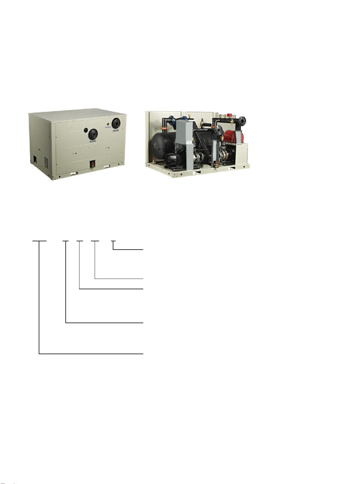
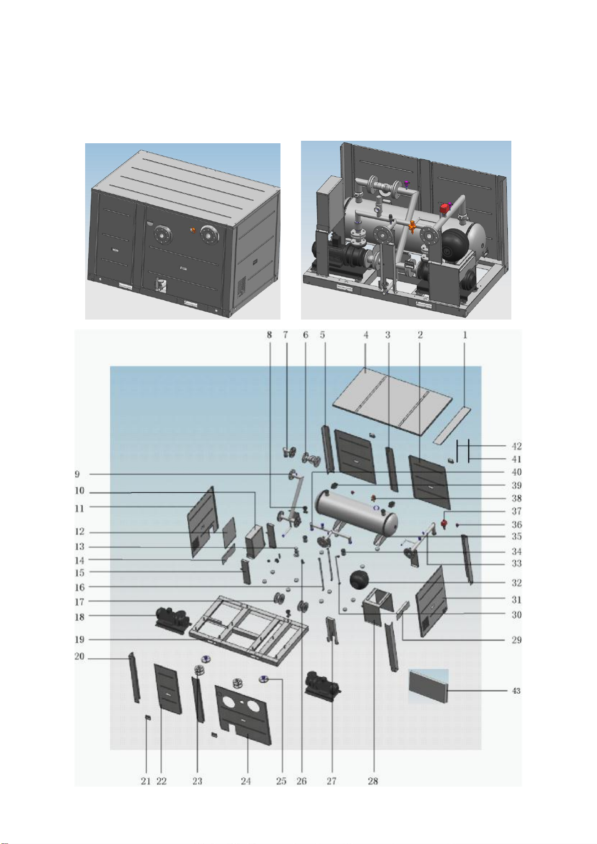
1 Introduction
The series hydraulic module is designed for air-cooled scroll chiller unit, it built-in two pumps, one is backup. The water pump can
be automatic switching under failure (malfunction shifting). It is the use of the hydraulic module integration solutions, is a
completely prefabricated sets strict monitoring of products, with a pump, valve, automatic replenishment, safety components,
bypass components, drain dirty sewage and control system, etc. For water cycle, constant pressure to supply water for all water
media transportation, for industrial, commercial and residential buildings, it is the best choice for water distribution system.
Capacity range:
Applies to air-cooled scroll chiller from 65&130kW.
2 Feature
2.1 Backup function
It built-in two pumps, one is backup. It can be automatically switched between two pumps in failure.
2.2 High-class main components
It adopts dustproof and waterproof designed for main components. For the pipe, it adopts brass, stainless steel or metal with
special coating and anti-rust treatment.
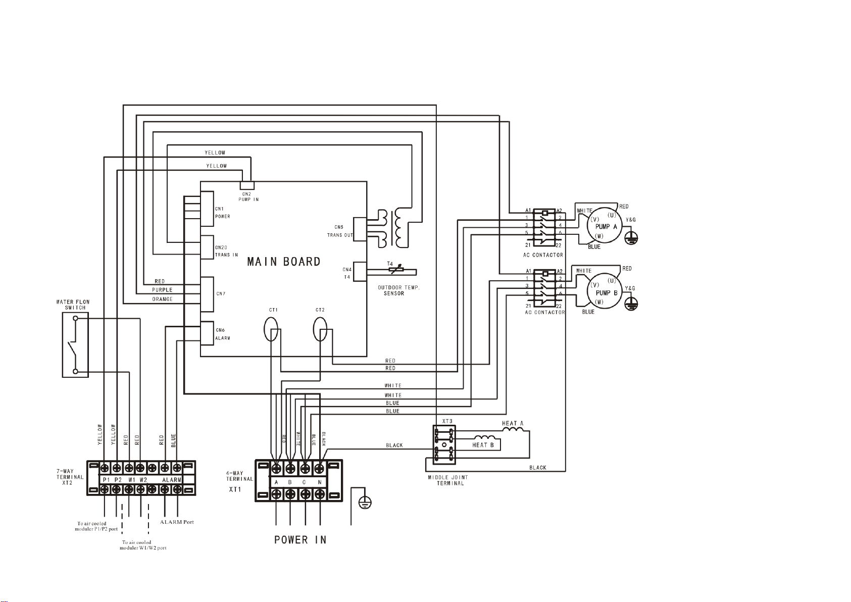
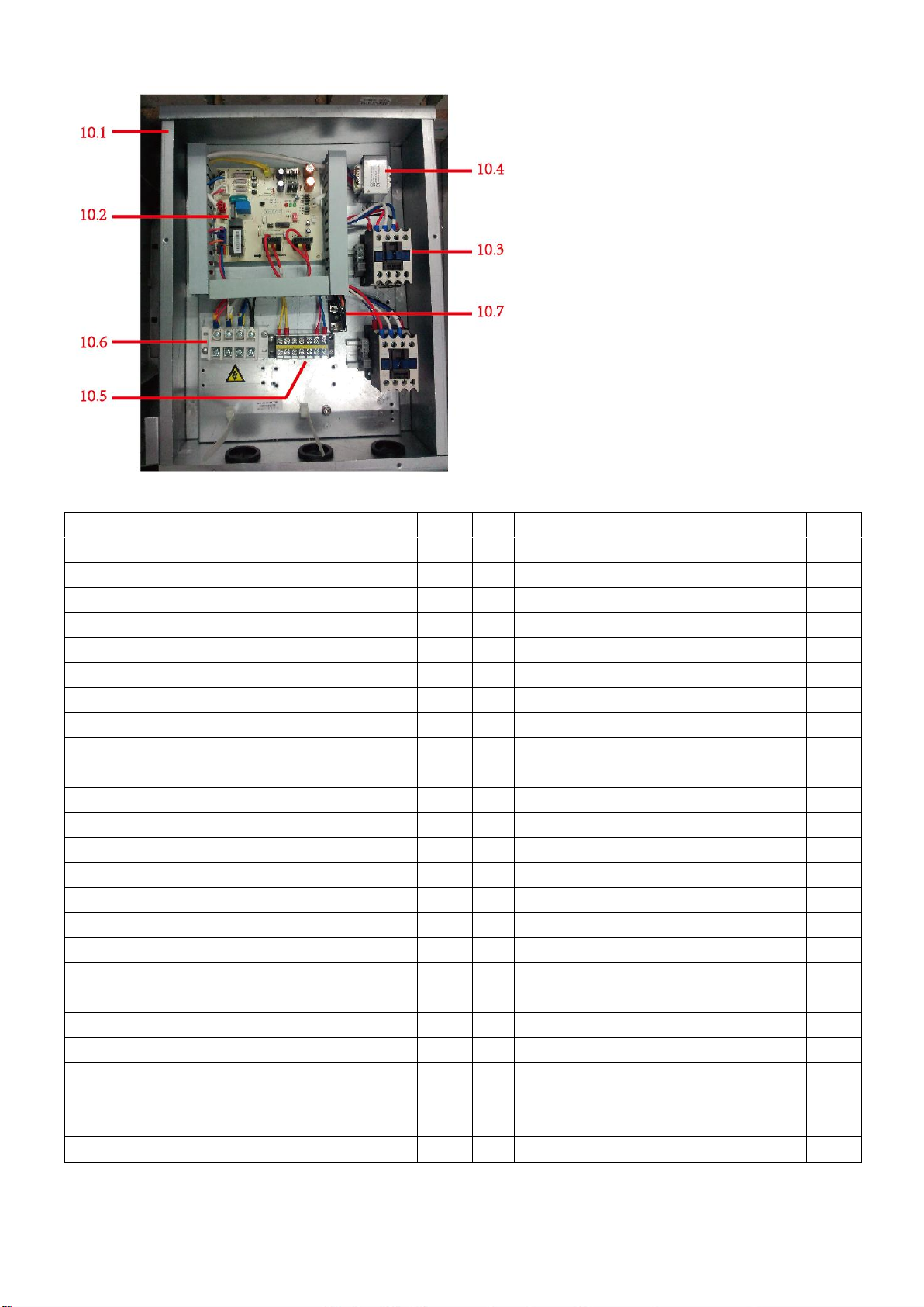
2.3 Intelligent control, energy security
The control cabinet can achieve linkage control with any formal air-condition mainframe through active or passive junction.
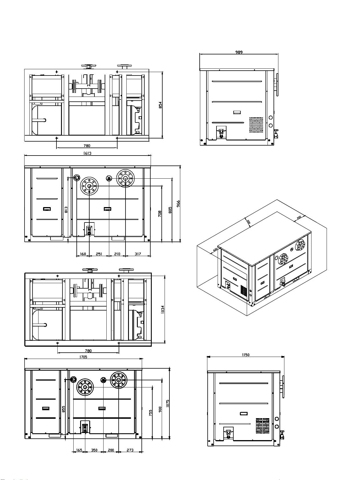
2.4 Easy installation and maintenance
The unit can be installed indoor or outdoor, suit for different customer’s requirement. There are screw connecting and flange
connecting, convenient for connecting.
2.5 Save the installation space and cost.
Integrated design, covering area is small. Intelligent control, it saves energy more than 30% than traditional. For air-cooled
scroll chiller, it’s no need expansion tank.
2.6 Fixed pressure replenishing water valve
It consists of reducing valve, stop valve and check valve. The automatic replenishment valve consists reduced pressure and
stable pressure device, the pressure value can be automatically adjusted and kept, which according to pressure gauge and the
replenishment valve scale, when the system pressure is low, it will be automatically open to filling water, automatically close
when the pressure up to setting value, avoid to damage system device cause of high pressure.
Maximum pressure of inlet water:10 bar
The pressure adjustment range:0.5~4 bar
To W1/W2 PORT of air cooled
scroll chiller
Signal from P1/P2 port of
air cooled scroll chiller