manuals.online logo
Brands
  1. Home
  2. •
  3. Brands
  4. •
  5. Daikin
  6. •
  7. Inverter
  8. •
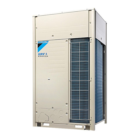
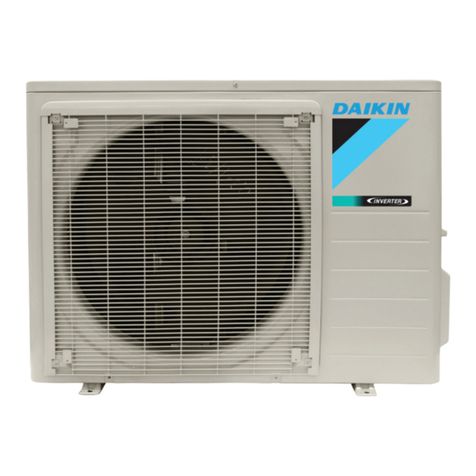
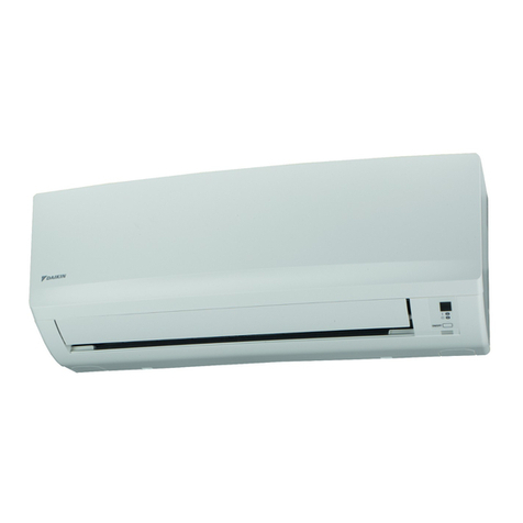
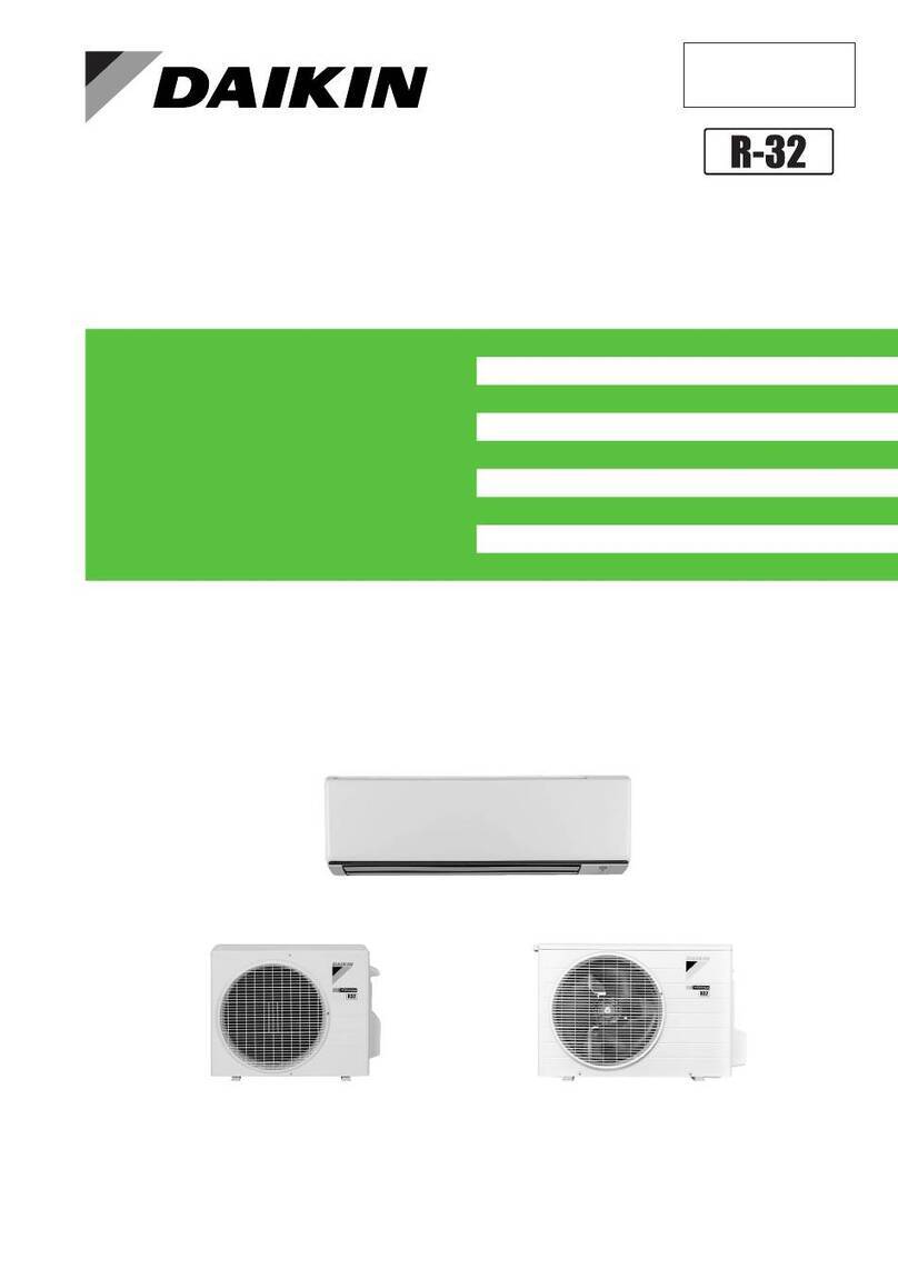
  9. Daikin RX-W Series User manual

Daikin RX-W Series User manual

Other manuals for RX-W Series

1

This manual suits for next models

3

Other Daikin Inverter manuals

Daikin FTXG-J User manual

Daikin

Daikin FTXG-J User manual

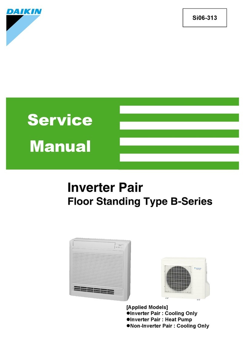
Daikin B-Series User manual

Daikin

Daikin B-Series User manual

Daikin LX10F11B3 User manual

Daikin

Daikin LX10F11B3 User manual

Daikin G-Series User manual

Daikin

Daikin G-Series User manual

Daikin J Series User manual

Daikin

Daikin J Series User manual

Daikin FTK Series User manual

Daikin

Daikin FTK Series User manual

Daikin ERX125A7W1B User manual

Daikin

Daikin ERX125A7W1B User manual

Daikin CTXU25G2V1B User manual

Daikin

Daikin CTXU25G2V1B User manual

Daikin 18000 Btu User manual

Daikin

Daikin 18000 Btu User manual

Daikin DX20VC Series Operating instructions

Daikin

Daikin DX20VC Series Operating instructions

Daikin FTK25JV1NB User manual

Daikin

Daikin FTK25JV1NB User manual

Daikin FLXS-BAVMB User manual

Daikin

Daikin FLXS-BAVMB User manual

Daikin K-Series User manual

Daikin

Daikin K-Series User manual

Daikin F-Series User manual

Daikin

Daikin F-Series User manual

Daikin FTKM-U Series User manual

Daikin

Daikin FTKM-U Series User manual

Daikin E Series User manual

Daikin

Daikin E Series User manual

Daikin DZ20VC Series Operating instructions

Daikin

Daikin DZ20VC Series Operating instructions

Daikin RXQ6AYM User manual

Daikin

Daikin RXQ6AYM User manual

Daikin FTXL25J2V1B User manual

Daikin

Daikin FTXL25J2V1B User manual

Daikin VRV User manual

Daikin

Daikin VRV User manual

Daikin H-Series User manual

Daikin

Daikin H-Series User manual

Daikin H-Series User manual

Daikin

Daikin H-Series User manual

Daikin VRV K User manual

Daikin

Daikin VRV K User manual

Daikin E Series User manual

Daikin

Daikin E Series User manual

Popular Inverter manuals by other brands

Omnik New Energy Omniksol-1.5k-TL user manual

Omnik New Energy

Omnik New Energy Omniksol-1.5k-TL user manual

Agilent Technologies 33250A user guide

Agilent Technologies

Agilent Technologies 33250A user guide

4-noks ZR-SWITCH-RC instruction manual

4-noks

4-noks ZR-SWITCH-RC instruction manual

V&T V5 Series user manual

V&T

V&T V5 Series user manual

Hon Turing HT-T-S1000-12 introduction

Hon Turing

Hon Turing HT-T-S1000-12 introduction

Metabo E 140 SP Plus Original operating instructions

Metabo

Metabo E 140 SP Plus Original operating instructions

BARRON EXITRONIX Tucson Micro Series installation instructions

BARRON

BARRON EXITRONIX Tucson Micro Series installation instructions

Baumer HUBNER TDP 0,2 Series Mounting and operating instructions

Baumer

Baumer HUBNER TDP 0,2 Series Mounting and operating instructions

electroil ITTPD11W-RS-BC Operation and Maintenance Handbook

electroil

electroil ITTPD11W-RS-BC Operation and Maintenance Handbook

Silicon Solar TPS555-1230 instruction manual

Silicon Solar

Silicon Solar TPS555-1230 instruction manual

Mission Critical Xantrex Freedom SW-RVC owner's guide

Mission Critical

Mission Critical Xantrex Freedom SW-RVC owner's guide

HP 3312A Operating and service manual

HP

HP 3312A Operating and service manual

Hoymiles HM-500T user manual

Hoymiles

Hoymiles HM-500T user manual

Nitecore SPM10 user manual

Nitecore

Nitecore SPM10 user manual

AEG Protect PV installation manual

AEG

AEG Protect PV installation manual

On Board TruePower Plus 1200MS owner's manual

On Board

On Board TruePower Plus 1200MS owner's manual

Plugreen PGM-200P-230 Installation and operation manual

Plugreen

Plugreen PGM-200P-230 Installation and operation manual

Fourgroup Easy use and Programming Handbook

Fourgroup

Fourgroup Easy use and Programming Handbook

manuals.online logo
manuals.online logoBrands
  • About & Mission
  • Contact us
  • Privacy Policy
  • Terms and Conditions

Copyright 2025 Manuals.Online. All Rights Reserved.

[Applied Models]
Inverter Pair : Heat Pump
Service
Manual
SiUS092230E
Inverter Pair RX-W Series
SiUS092230E
iTable of Contents
Introduction ....................................................................................... 1
1. Safety Cautions...........................................................................................2
1.1 Warnings and Cautions Regarding Safety of Workers................................. 2
1.2 Warnings and Cautions Regarding Safety of Users..................................... 4
2. Icons Used ..................................................................................................7
3. Revision History ..........................................................................................8
Part 1 General Information ............................................................... 9
1. Applicable Models .....................................................................................10
2. Functions...................................................................................................11
Part 2 Specifications....................................................................... 13
1. Specifications ............................................................................................14
1.1 Wall Mounted Type .................................................................................... 14
1.2 Duct Concealed Type................................................................................. 17
1.3 Ceiling Cassette Type ................................................................................ 20
Part 3 Printed Circuit Board Connector Wiring Diagram................ 22
1. Indoor Unit.................................................................................................23
1.1 FTXR09/12/18WVJUW(S)9........................................................................ 23
1.2 FDMQ09/12/15/18/24WVJU9..................................................................... 25
1.3 FFQ09/12/15/18W2VJU9 ........................................................................... 27
2. Sensor Kit for FFQ Series .........................................................................28
2.1 BRYQ60A2W(S)......................................................................................... 28
3. Wired Remote Controller...........................................................................29
3.1 BRC1E73 ................................................................................................... 29
4. Wireless Remote Controller Receiver for FDMQ Series ...........................30
4.1 BRC082A43 ............................................................................................... 30
5. Wireless Remote Controller Kit for FFQ Series ........................................31
5.1 BRC082A41W, BRC082A42W(S).............................................................. 31
6. Outdoor Unit..............................................................................................32
6.1 RX09/12WMVJU9 ...................................................................................... 32
6.2 RX15/18/24WMVJU9 ................................................................................. 34
Part 4 Functions and Control .......................................................... 36
1. Common Functions ...................................................................................38
1.1 Temperature Control .................................................................................. 38
1.2 Frequency Principle.................................................................................... 38
2. Functions for FTXR Series........................................................................40
2.1 Airflow Direction Control............................................................................. 40
2.2 Fan Speed Control for Indoor Unit ............................................................. 41
2.3 Program Dry Operation .............................................................................. 42
2.4 Automatic Cooling/Heating Changeover .................................................... 43
2.5 Thermostat Control..................................................................................... 44
SiUS092230E
Table of Contents ii
2.6 NIGHT SET Mode ...................................................................................... 45
2.7 ECONO Operation .................................................................................... 45
2.8 2-Area INTELLIGENT EYE Operation ....................................................... 46
2.9 POWERFUL Operation .............................................................................. 48
2.10 Multi-Monitor Lamp/TIMER Lamp .............................................................. 49
2.11 Clock Setting .............................................................................................. 50
2.12 WEEKLY TIMER Operation ....................................................................... 51
2.13 Other Functions.......................................................................................... 57
3. Functions for FDMQ/FFQ Series ..............................................................58
3.1 Airflow Direction Control............................................................................. 58
3.2 Fan Speed Control for Indoor Unit ............................................................. 59
3.3 Program Dry Operation .............................................................................. 60
3.4 Clock and Calendar Setting (With BRC1E73) ............................................ 61
3.5 Schedule Timer Operation (With BRC1E73).............................................. 63
3.6 Setback Function (With BRC1E73) ............................................................ 67
3.7 Drain Pump Control.................................................................................... 68
3.8 Hot Start Control (In Heating Operation Only)............................................ 70
3.9 Presence and Floor Sensors (Option)........................................................ 71
3.10 Other Functions.......................................................................................... 74
4. Thermistor Functions ................................................................................76
5. Control Specification .................................................................................77
5.1 Mode Hierarchy .......................................................................................... 77
5.2 Frequency Control...................................................................................... 77
5.3 Controls at Mode Changing/Start-up.......................................................... 79
5.4 Discharge Pipe Temperature Control......................................................... 82
5.5 Input Current Control.................................................................................. 83
5.6 High Pressure Protection Control............................................................... 84
5.7 Freeze-up Protection Control ..................................................................... 85
5.8 Heating Peak-cut Control ........................................................................... 86
5.9 Outdoor Fan Control................................................................................... 87
5.10 Liquid Compression Protection Function.................................................... 87
5.11 Defrost Control ........................................................................................... 88
5.12 Electronic Expansion Valve Control ........................................................... 89
5.13 Malfunctions ............................................................................................... 92
Part 5 Remote Controller ................................................................ 93
1. Applicable Remote Controller ...................................................................94
2. ARC466A36 ..............................................................................................95
3. BRC082A43 ..............................................................................................97
4. BRC082A41W, BRC082A42W(S).............................................................99
5. BRC944B2 ..............................................................................................101
6. BRC1E73 ................................................................................................102
SiUS092230E
iii Table of Contents
Part 6 Service Diagnosis ............................................................... 108
1. General Problem Symptoms and Check Items .......................................110
2. Troubleshooting with LED .......................................................................111
2.1 Indoor Unit................................................................................................ 111
2.2 Outdoor Unit ............................................................................................. 113
3. Service Diagnosis ...................................................................................114
3.1 ARC466 Series......................................................................................... 114
3.2 BRC1E73 ................................................................................................. 117
3.3 BRC082A43, BRC082A41W, BRC082A42W(S)...................................... 119
4. Error Codes and Description...................................................................123
5. Troubleshooting for FTXR Series............................................................124
5.1 Indoor Unit PCB Abnormality ................................................................... 124
5.2 Freeze-up Protection Control/Heating Peak-cut Control .......................... 126
5.3 Indoor Fan Motor (DC Motor) or Related Abnormality ............................. 127
5.4 Thermistor or Related Abnormality........................................................... 130
5.5 Front Panel Open/Close Fault.................................................................. 131
5.6 Low-voltage Detection or Over-voltage Detection.................................... 132
5.7 Signal Transmission Error (Between Indoor Unit and Outdoor Unit)........ 134
5.8 Unspecified Voltage (Between Indoor Unit and Outdoor Unit) ................. 136
6. Troubleshooting for FDMQ, FFQ Series .................................................137
6.1 Indoor Unit PCB Abnormality ................................................................... 137
6.2 Drain Level Control System Abnormality.................................................. 138
6.3 Indoor Fan Motor or Related Abnormality ................................................ 139
6.4 Indoor Fan PCB Abnormality.................................................................... 144
6.5 Humidifier or Related Abnormality............................................................ 145
6.6 Thermistor or Related Abnormality........................................................... 146
6.7 Presence Sensor or Floor Sensor Abnormality ........................................ 147
6.8 Remote Controller Thermistor Abnormality .............................................. 148
6.9 Low-voltage Detection or Over-voltage Detection.................................... 149
6.10 Signal Transmission Error (Between Indoor and Outdoor Unit) ............... 151
6.11 Signal Transmission Error (Between Indoor Unit and
Remote Controller) ................................................................................... 153
6.12 Signal Transmission Error (Between MAIN/SUB Remote Controllers) .... 154
6.13 Unspecified Voltage (Between Indoor Unit and Outdoor Unit) ................. 155
7. Troubleshooting for Outdoor Unit............................................................156
7.1 Outdoor Unit PCB Abnormality................................................................. 156
7.2 Actuation of High Pressure Switch ........................................................... 157
7.3 OL Activation (Compressor Overload) or HPS Activation
(High Pressure Switch)............................................................................. 159
7.4 OL Activation (Compressor Overload) ..................................................... 162
7.5 Compressor Lock ..................................................................................... 165
7.6 DC Fan Lock ............................................................................................ 166
7.7 Input Overcurrent Detection ..................................................................... 167
7.8 Four Way Valve Abnormality.................................................................... 169
7.9 Discharge Pipe Temperature Control....................................................... 171
7.10 High Pressure Control in Cooling ............................................................. 172
SiUS092230E
Table of Contents iv
7.11 System Shutdown due to Temperature Abnormality in
the Compressor........................................................................................ 174
7.12 Compressor Sensor System Abnormality ................................................ 175
7.13 Position Sensor Abnormality .................................................................... 176
7.14 DC Voltage/Current Sensor Abnormality.................................................. 179
7.15 Thermistor or Related Abnormality (Outdoor Unit)................................... 180
7.16 Electrical Box Temperature Rise.............................................................. 182
7.17 Radiation Fin Temperature Rise .............................................................. 183
7.18 Output Overcurrent Detection .................................................................. 185
8. Check ......................................................................................................188
8.1 Thermistor Resistance Check .................................................................. 188
8.2 Indoor Fan Motor Connector Check ......................................................... 189
8.3 Power Supply Waveform Check............................................................... 190
8.4 Electronic Expansion Valve Check........................................................... 191
8.5 Four Way Valve Performance Check ....................................................... 192
8.6 Inverter Unit Refrigerant System Check ................................................... 192
8.7 Inverter Analyzer Check ........................................................................... 193
8.8 Outdoor Fan Motor Check........................................................................ 196
8.9 Installation Condition Check..................................................................... 197
8.10 Discharge Pressure Check....................................................................... 197
8.11 Outdoor Fan System Check ..................................................................... 198
8.12 Main Circuit Short Check.......................................................................... 198
8.13 Power Module Check ............................................................................... 200
Part 7 Trial Operation and Field Settings ..................................... 202
1. Pump Down Operation............................................................................203
2. Forced Cooling Operation.......................................................................204
3. Trial Operation ........................................................................................206
3.1 FTXR Series............................................................................................. 206
3.2 FDMQ, FFQ Series .................................................................................. 207
4. Field Settings for FTXR Series................................................................210
4.1 Temperature Display Switch .................................................................... 210
4.2 When 2 Units are Installed in 1 Room...................................................... 210
4.3 Jumper and Switch Settings..................................................................... 211
5. Field Settings for FDMQ, FFQ Series .....................................................212
5.1 How to Change the Field Settings............................................................ 212
5.2 Overview of Field Settings for FDMQ Series............................................ 215
5.3 Overview of Field Settings for FFQ Series ............................................... 216
5.4 MAIN/SUB Setting when Using 2 Wired Remote Controllers................... 217
5.5 MAIN/SUB and Address Setting for Wireless Remote Controller
for FDMQ Series ...................................................................................... 218
5.6 MAIN/SUB and Address Setting for Wireless Remote Controller
for FFQ Series.......................................................................................... 221
6. Field Settings for Outdoor Unit................................................................224
6.1 Facility Setting (cooling at low outdoor temperature) ............................... 224
6.2 Warmer Airflow Setting............................................................................. 225
6.3 Drain Pan Heater...................................................................................... 226
SiUS092230E
vTable of Contents
7. Silicone Grease on Power Transistor/Diode Bridge................................227
Part 8 Appendix ............................................................................. 228
1. Piping Diagrams......................................................................................229
1.1 Indoor Unit................................................................................................ 229
1.2 Outdoor Unit ............................................................................................. 230
2. Wiring Diagrams......................................................................................232
2.1 Indoor Unit................................................................................................ 232
2.2 Outdoor Unit ............................................................................................. 235
3. Operation Limit........................................................................................237
SiUS092230E
Introduction 1
1. Safety Cautions...........................................................................................2
1.1 Warnings and Cautions Regarding Safety of Workers................................. 2
1.2 Warnings and Cautions Regarding Safety of Users..................................... 4
2. Icons Used ..................................................................................................7
3. Revision History ..........................................................................................8
Introduction
Safety Cautions SiUS092230E
2Introduction
1. Safety Cautions
Be sure to read the following safety cautions before conducting repair work.
After the repair work is complete, be sure to conduct a test operation to ensure that the equipment
operates normally, and explain the cautions for operating the product to the customer.
Caution Items The caution items are classified into Warning and Caution. The Warning items are
especially important since death or serious injury can result if they are not followed closely. The
Caution items can also lead to serious accidents under some conditions if they are not
followed. Therefore, be sure to observe all the safety caution items described below.
Pictograms This symbol indicates an item for which caution must be exercised.
The pictogram shows the item to which attention must be paid.
This symbol indicates a prohibited action.
The prohibited item or action is shown in the illustration or near the symbol.
This symbol indicates an action that must be taken, or an instruction.
The instruction is shown in the illustration or near the symbol.
1.1 Warnings and Cautions Regarding Safety of Workers
This manual is for the
person in charge of
maintenance and
inspection.
Warning
Do not store equipment in a room with fire sources (e.g., naked
flames, gas appliances, electric heaters).
Be sure to disconnect the power cable from the socket before
disassembling equipment for repair.
Working on equipment that is connected to the power supply may cause
an electrical shock.
If it is necessary to supply power to the equipment to conduct the repair or
inspect the circuits, do not touch any electrically charged sections of the
equipment.
If refrigerant gas is discharged during repair work, do not touch the
discharged refrigerant gas.
Refrigerant gas may cause frostbite.
When disconnecting the suction or discharge pipe of the
compressor at the welded section, evacuate the refrigerant gas
completely at a well-ventilated place first.
If there is gas remaining inside the compressor, the refrigerant gas or
refrigerating machine oil discharges when the pipe is disconnected, and it
may cause injury.
If refrigerant gas leaks during repair work, ventilate the area.
Refrigerant gas may generate toxic gases when it contacts flames.
SiUS092230E Safety Cautions
Introduction 3
Be sure to discharge the capacitor completely before conducting
repair work.
The step-up capacitor supplies high-voltage electricity to the electrical
components of the outdoor unit.
A charged capacitor may cause an electrical shock.
Do not turn the air conditioner on or off by plugging in or
unplugging the power cable.
Plugging in or unplugging the power cable to operate the equipment may
cause an electrical shock or fire.
Be sure to wear a safety helmet, gloves, and a safety belt when
working in a high place (more than 2 m (6.5 ft)).
Insufficient safety measures may cause a fall.
In case of R-32 / R-410A refrigerant models, be sure to use pipes,
flare nuts and tools intended for the exclusive use with the R-32 /
R-410A refrigerant.
The use of materials for R-22 refrigerant models may cause a serious
accident, such as a damage of refrigerant cycle or equipment failure.
Do not mix air or gas other than the specified refrigerant (R-32 /
R-410A / R-22) in the refrigerant system.
If air enters the refrigerant system, an excessively high pressure results,
causing equipment damage and injury.
Caution
Do not repair electrical components with wet hands.
Working on the equipment with wet hands may cause an electrical shock.
Do not clean the air conditioner with water.
Washing the unit with water may cause an electrical shock.
Be sure to provide an earth / grounding when repairing the
equipment in a humid or wet place, to avoid electrical shocks.
Be sure to turn off the power switch and unplug the power cable
when cleaning the equipment.
The internal fan rotates at a high speed, and may cause injury.
Be sure to conduct repair work with appropriate tools.
The use of inappropriate tools may cause injury.
Warning
Safety Cautions SiUS092230E
4Introduction
1.2 Warnings and Cautions Regarding Safety of Users
Be sure to check that the refrigerating cycle section has cooled
down enough before conducting repair work.
Working on the unit when the refrigerating cycle section is hot may cause
burns.
Conduct welding work in a well-ventilated place.
Using the welder in an enclosed room may cause oxygen deficiency.
Caution
Warning
Do not store the equipment in a room with fire sources (e.g., naked
flames, gas appliances, electric heaters).
Be sure to use parts listed in the service parts list of the applicable
model and appropriate tools to conduct repair work. Never attempt
to modify the equipment.
The use of inappropriate parts or tools may cause an electrical shock,
excessive heat generation or fire.
If the power cable and lead wires are scratched or have deteriorated,
be sure to replace them.
Damaged cable and wires may cause an electrical shock, excessive heat
generation or fire.
Do not use a joined power cable or extension cable, or share the
same power outlet with other electrical appliances, since it may
cause an electrical shock, excessive heat generation or fire.
Be sure to use an exclusive power circuit for the equipment, and
follow the local technical standards related to the electrical
equipment, the internal wiring regulations, and the instruction
manual for installation when conducting electrical work.
Insufficient power circuit capacity and improper electrical work may cause
an electrical shock or fire.
Be sure to use the specified cable for wiring between the indoor and
outdoor units.
Make the connections securely and route the cable properly so that there
is no force pulling the cable at the connection terminals.
Improper connections may cause excessive heat generation or fire.
When wiring between the indoor and outdoor units, make sure that
the terminal cover does not lift off or dismount because of the cable.
If the cover is not mounted properly, the terminal connection section may
cause an electrical shock, excessive heat generation or fire.
Do not damage or modify the power cable.
Damaged or modified power cables may cause an electrical shock or fire.
Placing heavy items on the power cable, or heating or pulling the power
cable may damage it.