Shure HTS Series User manual


CAUTION
UTION:
TO REDUCETHE RISK OF ELECTRI
DO
NOT REMOVE COVER
NO USER-SERVICEABLE
PARTS INSIDE.
REFER SERVICINGTO QUALIFIEDSERVICEPERSONNEL
Under
FCC
Rules,changes or modifications not expressly ap-
proved
by
Shure Brothers Inc. could void your authority to
operate this device.
The lightning flash with
arrowhead symbol, with-
inan equilateraltriangle,
is intended to alert the
user to presence of un-
insulated "dangerous
voltage" within the pro-
duct'senclosurethatmay
beof sufficientmagnitude
to constitute a risk of
electricshocktopersons.
The exclamation point
within an equilateral tri-
angleis intendedto alert
the user
to
the presence
of important operating
and maintenance (sew-
icing) instructionsin the
literatureaccompanying
the appliance.

USER'S
GUlDE

HTS5OSW
SUBWOOFER
CENTER
FR(
HTSSOLKS
LEFI',
KIGHT. SURROLNI)
LOUDSPEAKER
HTSSOCF
)hT
SPEAKER
HOME THEATER REFERENCE SYSTEM COMPONENTS
t

SHURE HTS
ACRA-VECTOR@*HOME THEATER REFERENCE SYSTEM
CONTENTS
..........................
General Description
6
.........................
HTS Reference System
7
HTS5300 Decoder
........................
7
.......................
HTSSOSPA Amplifier
7
........................
HTS5OCF Speaker
7
........................
HTSSOLRS Speaker
8
......................
HTS5OSW Subwoofer 8
........................
Locating Speakers
8
..........
HTS Reference System Interconnections 10
...................
Source to Decoder 10
Decoder to Amplifier and Speakers
.........
10
.................
Initial Setup and Operation 12
..................
Pushbutton Controls 12
.....................
Rotary Controls
12
.....................
Graphic Display 13
.....................
Remote Control 13
....................
Remote Extender 13
.................
Mono Enhance Adjust 14
......................
Balance and Phasing 14
..............................
Mixed System 14
.......................
Locating Speakers 14
........................
Interconnections 15
...................
Source to Decoder 15
Decoder to Amplifiers and Speakers
........
15
......................
Balance and Phasing 16
............................
Troubleshooting 17
...........................
Program Material
18
..............................
Specifications 18
*US
Patents
4.696.036
and
4.811.
019

SBGRE HTS ACRA-VECTORcR)*HOME THEATER
SOliND
(:or~~ratul,tt~o~i\'\our Sliure il'l'S Acra lector
"
I-lomeTllcater
Kefc.rcncc. iird~o>)\tern prov~de\thc \torld's finest IIome
I'1ic~;tterSouncl Yoour Iiome theatcr equ~ppedwith a Shure IITS
lkferen~eS\\ten~
\ill1
;tchle\c the same real~smand ~mmedlacj
ot
soiinti
th,lt !lo11 hear In the
~cr)
be\t motlon plcture theaters
cclu~pl)~(l\iltl~1)olbj Stvrco
'
*
For
tlio4e
nho
re
not tot'11I) hnllllar with 1)olh) Stereo.
1)olh) Surrountl, lcm-lector dccoillng, ant1 Horne Theater
So~ind.sonic e\pl,ul,~t~onrfollon
00
DOLBY
STEREO**
ticscrihcs a motion
picture
process.
one part of ~vliichincludes
recording
films \+ith tllrec front
cli;rn~icls(Left, (knttr. Right) ant1 one rc;ir (or surrou~itl)
c11:tnncl. 'i'he I)olh!. Stereo theatcr encotling-tk'cocli~lgprocess
uscs
;I
mat1iematic;l1it1coclc to con~hinethe fi~urautlio tracks into
t\zo stereo t~~cb,then h;uh into the four original track (kno\+n
as
:I
t-2--4
process for short).
\lilllcn
1)olby Stereo filriis are
transferreti to thc video format, the
encoded
sountl tracks are
presenctl. iuitl are
now
c;~lletl
0U
DOLBY SLRROL'ND.
ACKA-VECTOR 1)ECODING
'The p;~tcntcdShure Escl~isivehcra-l'cctor Logic decoding
process
LISCS
logic
CII~I;IIICCIII~~~
circuits ivhicli recover tlie
original fi)ur recortled channels tt.ith a high degree of separation
het~vernadjaccnt cli;u~ncls.'l'he :Icra-Vector l)ecoder cmulatcs
the I)olh! Stereo thcatcr dccotler ;uid permits all listeners.
~iIiere\~erthey are locatetl in the horiie theater, tc; cnjoy the
tot:~l {heatereupericnce.
SIII'REIfl'S
In
ortlcr to ti~llyreplicate tlie 1)oby Stereo theater
experience
in the Sli~irct1'i'S Ilome Theater, the Sliure II'TSi.300 1)rcotler
provides in adtlition to
;\era-\'cctor
logic enhancement:
'I'lie \title dynamic range and high signal-to-noise ratio
ncccssar) for (banlatic contrast
'I'lie atIjust;cblc dela~ytime recluirecl for tailoring to rooms
of \.arious size
Thc
cuclusivc
:\caustic
Space (;enerator that immerses
evcJnlistener in
the
fill1 spatial field tvith
a
minimum
number of surrountl spe;~kers
'I'hc suhuoofer output intcgral to tlie cre;ttion
of
mood
and place.
HOME THEATER, WHAT YOU NEED
The Source
I'rogram material
from
a 1)olhy Stereo Soura' (t:.g..video
disc plajer, video tape player. stereo t\./;~uciioreccbivc:r)in which
thr. original four-channcl audio recording lias been encotled or
mixed docv~ito two stereo tracks is decotled
and
reprotluced
by a Ilome Theater Sountl system.
The Room
:\
common misconception is that
a
very large room is
requiretl to enjoy the re-creation of theater ;mibierice in the
home. l'he Sl~ureH1'S process ;~lloivsall tlie enjoyment
of
;I
theatrical perfornmance in
a
room of motiest size. I.argcr rooms,
of
course, are also highly suitable for hornc theater.
The Video
.A
realistic honie theatcr experience rnay be ;~chir\ahlcwit11
an ortlinan honir television screen in rooms of ordinary size.
A
projection
tv
is popular
in
1;lrger rooms. In gcncfitl, the Ii~rgest
screen practical for the room is preferretl.
The Audio
In the movie theatcr
a
high performance audio system
contributes just
as
much
as
tlie large screen to the participatorj
qu;~lity
of
the experience.
To
tluplicatc this quality in the home,
the system must
bc
capable of producing high sound pressure
levels with low distortion not only
in
the front channels but
also in the surround channels
nil
the sulnvoofr~r(orlow
frerjuency) channel.
:2
center ti-ont ch;~nnelloudspeaker is of
great importance in maintaining proper audio perspecthrefor
all viewers.
In
order to obtain the optinium listening experit:nce with a
home theater audio system, it is important to select ;urnplificrs
and loudspeakers that are capable of producing the required
low distortion, high sound pressure levels. precise localization.
ant1 fitlelity to the original source. Shure's IlTS Division has
tieveloped such a system of matched components for a reference
standarcl honie theater system. As
a
basis for tletertnining
requirements for home theater, consider that the sound system
in a modern movie theater is designed to generate maximum
peak
sound pressure levels of
108
dB
SI'I, at an ideal viewing
position.

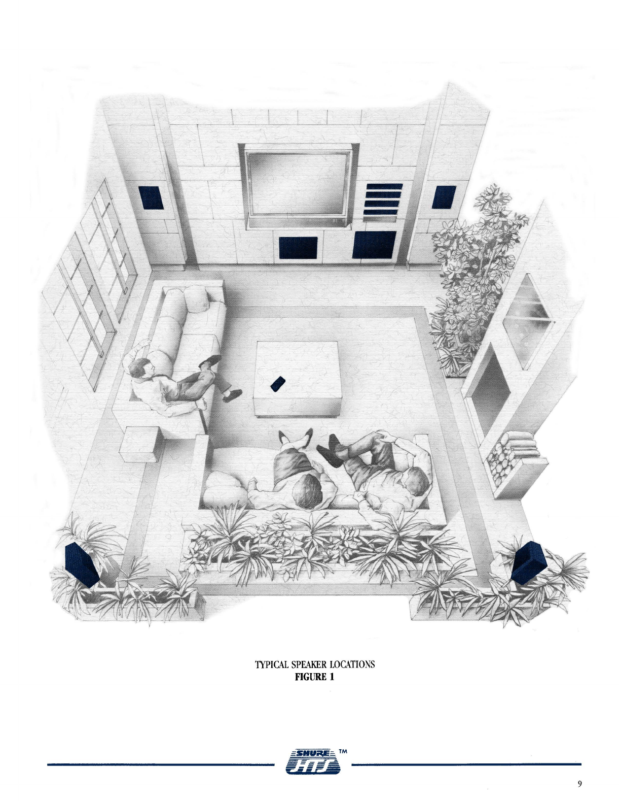
THE SHURE HTS REFERENCE SYSTEM
A
number of Reference Systems can be constructed using
Shure HTS Theater Reference System Components. Please consult
with your Authorized HTS Dealer in order to determine which
Reference system best suits
your
specific needs. The system
described below is ideal for rooms of average size. It consists
of the following components:
1
Dolby Stereo Source
1
HTS5300 Acra-Vector Logic Decoder
3 HTSSOSPA Signal Processing Stereo Power Amplifiers
1
HTSSOCF Center Front Loudspeaker System
4
HTSSOLRS Loudspeakers
1
HTSSOSW Subwoofer Loudspeaker
1
Video display monitor or
'ITr
1
Switchable power strip with
6
(or more) sockets
HTS5300 ACRA-VECTOR LOGIC DECODER
The Shure HTS Acra-Vector Logic Decoder incorporates such
additional features as the Shure-designed Acoustic Space
Generator, true digital time delays that are user selectable for
individual room size and layout, input level and balance controls,
and a graphic readout of input signal strength at each channel.
These constituents significantly enhance the home listening
experience compared to rudimentary Surround processors. In
fact, the combination of Acra-Vector decoding with Shure's
Acoustic Space Generator provides, in a home space with front
left, right and center speakers, and only two surround speakers,
the same surround ambience that requires an array of eight to
ten speakers in a theater.
The Shure HTS Reference System also incorporates a
subwoofer loudspeaker for high-level low bass frequencies.
Because the film sound mixers use very low-frequency audio as
an integral part of the creation of mood and location, a
subwoofer reinforces the theater illusion and intensifies the
realism of the performance.
The HTS5300 is designed and built with meticulous attention
to detail and highest quality components used throughout. One
example of this philosophy of details is the use of gold-plated
input and output connectors on the Decoder itself and on the
supplied interconnecting cables.
HTSSOSPA SIGNAL PROCESSING AMPLIFIER
The HTSSOSPA amplifier has been designed to complement
the Shure HTS Decoder and Shure HTS Loudspeakers. The
HTSSOSPA amplifier has switch selectable Operational Modes in
each of which the amplifier response matches each HTS speaker
type.
For instance, in the LRS or CF modes, the amplifier output
is full range and precisely complements the HTSSOLRS or
HTSSOCF loudspeaker response respectively. On the other hand,
when Channel
1
is in Operational Mode SW, amplifier output
extends from 33 to 80 Hz to match the frequency response of
the HTSSOSW Subwoofer. In addition, to further enhance its
versatility,each channel of the HTSSOSPA amplifier also includes
a "Flat" output mode, making it suitable for use with any
loudspeaker.
In each channel, the HTSSOSPA includes a dynamically variabie
limiter that continuously measures the input signal and shapes
the response, depending on the Operational Mode selection, to
protect against distortion caused by overexcursion of the speaker
connected to that channel. An additional protection circuit
prevents long term hard clipping. The latter circuit can be
selectivelydisabled for each channel by pressing its Protection
Defeat switch.
In each of its HTS-speaker-correlatedoperational modes, the
wideband electronic response of the HTSSOSPA is tailored to
match the particular HTS loudspeaker system selected (HTSSOCF,
LRS, or SW). The design correlation between the amplifier
output and the loudspeaker/crossover interaction, loudspeaker-
to-room transfer function, and program-material-dependent
loudspeaker output at the listener position in a typical Home
Theater System has been achieved through extensive laboratory
testing and in situ program listening.
Consequently, the HTSSOSPA offers the user an amplifier that
is outstanding for high-quality audio/video theatrical
presentations in the home as well as one that provides a unique
experience in traditional multi-channel audio only listening.
Scrupulous care has been exercised in design and construction
of the HTSSOSPA with highest quality components used
throughout. Like the HTS5300, the HTSSOSI'A uses gold-plated
RCA phono jacks and additional gold-plated five-way binding
posts for loudspeaker output connectors.
HTSSOCF SPEAKER SYSTEM
The HTSSOCF Center Front speaker is compatible with the
HTSSOSPA power amplifier. In a top quality home theater sound
system, the loudspeaker used in the center front position is
subject to the most rigorous performance demands in terms of
power handling. The HTSSOCF meets those demands; its
performance has been carefully matched to the HTSSOLRS Front
Left and Right speakers in order to provide uniform response
across the front sound stage with realistic pans and unparalleled
fidelity.When the HTSSOSPA Amplifier is in the CF Operational
Mode, the amplifier and speaker cut off at 80 Hz for a perfect
match to the HTSSOSW Subwoofer; in the CFx Mode, the low-
frequency rolloff point extends down to 60 Hz.

The HTSSOCF has two 6-1/2-inch low-frequency drivers and
a single 1-inch soft fabric, damped dome high frequency driver,
all equipped with heavyweight shielded double magnet systems
to reduce interference with the tv picture. The two way third
order/fourth order matched crossovers have impedance
equalization and a response-shaping filter to optimize on- and
off-axis power handling across the full frequency range.
Connectors are gold-plated five-way binding posts.
HTSSOLRS SPJNKER SYSTEM
The HTSSOLRS speaker is intended for use in both Front Left
and Right and Surround Left and Right positions; it has power
handling compatible with the HTSSOSPA power amplifier. Its
response is tailored to match the HTSSOCF Center Front Speaker.
When the amplifier is in the LRS Mode, the amplifier and
speaker cut off at 80 Hz for a perfect match to the HTSSOSW
Subwoofer; in the LRS, Mode, the low-frequencyrolloff point
extends down to 60 Hz.
The HTSSOLRS has a 6-1/2-inch low-frequencydriver and a
I
-inch soft hbric, damped dome high frequency driver with fluid
cooling. Both drivers are equipped with heavyweight shielded
double magnet systems to reduce interference with the tv
picture. The two way fourth order matched crossover has
impedance equahzation and response shaping flters. It has been
designed to optimize power handling across the frequency
spectrum both on- and off-axis. Connectors are gold-plated five-
way binding posts.
HTSSOSW SUBWOOFER SPWR
The HTSSOSW has a response of
33
to 80 Hz. Its response
is tailored to match the cutoffcharacteristics of both the
HTSSOCF and HTSSOLRS Loudspeakers when the HTSSOSPA
Power Amplifier is in Operational Modes CF
AND
LRS. This high
power, high fidelity subwoofer is intended for connection to
Channel 1 of the HTSSOSPA Stereo Amplifier in the
SW
OperationalMode. The HTSSOSW Subwoofer has power handling
characteristics completely compatible with the HTS amplifier.
Its 304 mm (12 in.) transducer has a heavy damped cone with
a rolled rubber surround and a 4.6 kg (10.2 Ib) shielded double
magnet structure to reduce interference with the
tv
picture. The
enclosure is high quality particle board, surface braced and cross
braced to reduce undesired cabinet vibrations. Connectors are
gold-plated five-way binding posts.
LOCATING
SPIZAKERS
Speaker location in each individual case will depend on the
size and shape of the room where the Home Theater System is
installed. The pictorial below (FIGURE 1) is intended as a
general guide to speaker placement.
HTS speakers are shielded to prevent interference with the
tv picture and can be located where desired with respect to
the tv screen.
Center Front
The HTSSOCF has been designed to be used in a
vertical
configuration for the center front positon. However, if space
does not permit the vertical position, the box can be rotated
90° to the right with minimal change in response and
dispersion. To maintain design integrity when the speaker is
horizontal, the loudspeaker grille should be rotated 180' and
reinserted into the baffle mounting holes. The Shure HTS logo
can also be reassigned if desired (see the HTSSOCF data sheet
for details).
Locate the center speaker as close as possible to the
centerline of the tv screen. With a rear projection
tv,
you can
often rest the HTSSOCF directly on the top surface of the
cabinet; with a front projection tv, there is usually room below
the screen; otherwise a shelf above the screen is likely the best
location. (A shelf should be capable of supporting a static load
of 67 kg [I48Ib], 4 times the weight of the speaker.) In the
cabinet top position, the loudspeaker should be located as close
as possible to the front cabinet edge (just above the screen)
to reduce undesirable wave reflections which degrade the sound
quality.
Front Left and Right
Use HTSSOLRS speakers for the front left and right positions.
Locate these speakers as far to each side of the screen as
possible.
Best imaging is obtained with
all
front speakers (Left, Right,
and
Center) at approximately the same height above the floor.
(Consult your Shure HTS dealer about suitable speaker stands.)
SurroundLeft and Right
Use HTSSOLRS speakers for the surround position. Locate
the surround left and right speakers either behind or to the
sides of the viewers. In either case, keep the surround speakers
as far apart as possible. We recommend the surround speakers
be elevated and angled toward the primary viewing area.
(Consult your Shure HTS dealer for appropriate speaker stands
or wall mounting hardware.)
Subwoofer
Because very low frequencies are non-directional in a room,
the HTSSOSW Subwoofer can usually be located at any
convenient place in the front of the room. If space does not
permit a front location, listen to determine the best position.

TYPICAL SPEAKER LOCATIONS
FIGURE
1

SHURE HTS REFERENCE SYSTEM
INTERCONNECTIONS
A.
SOURCE TO
DECODER
CONNECTIONS
'The HTSi.300 inputs accept ;lux level stereo output signals
hm
a stereo preamp or a video disc player, VCR, or
tv
receiver.
I:se one pair of the suppliect interconnecting cables for the
source to HTSi300 I, and R inputs.
1.
Single source
If a single source is used, connect the source's stereo
outpt~tstothe H'l'S5.300 INPUTS
L
and R. (See Figure
2)
STEREO
SOURCE
WX
OUT
"rmlr
KISm
OUTPUTS INPUT
=~+~k%&
CL"IEI1
OUIPUT
lo
wFj--2~w
0
0
&:;
LO
Mmr"
0
2.
Multiple sources
When multiple sources are to he decoded, i.e., a VCR,
rideo disc player, and broatlcast ti1as
well
as an audio-
only tape deck, it is most efficient to connect them all to
a
single unit, such
as
an audio/video snitcher or a stereo
pr~a11por receiver, and to connect that unit's stereo tape
outl~utstothe HTSi300 INPITS
L
and R. (See Figure 3)
AUDIO OUTPUTS
-
LASER
OlLC
PLllFR
0
Mi;;
0
-
0.0
3.
livo
audio sources connected direc* to the Decoder
A
secontl autlio source can be connected to the IITS5.300
TAPE RETURN Left
and
Right inputs. (Figure
4)
In this
case:
a. menthe front panel TAI'E
>ION
switch is
out,
the
HTSi3OO decodes the inputs from
L
and
K.
b.
Klihen the front panel TAI'E
$ION
switch is
in,
the
IITSi3OO decodes the inputs from 'I:-\I'E RE1'I.KN
L
and
K.
Sll1l:J'IPLE SOPRCES
'1'0
HTS4300
FIGLRE
3
DEPRESS
SkCO\I> SOlIRCE CONNEC'J'EI) TO IITSi300
x-\PE RETL'RN I'iPITS
FIGURE
4
B.
DECODER
TO AMPLIFIER AND SPEAKER
1.
Use the three rema~ningpairs of interconnecting cables
supplied with the HTSi3OO to connect the HTSSSOO
outputs to the H1'S50SPi4amplifier inputs. (See Figure
5.)The highest powr demands are presented by the
HTSSOCF Center Front Speaker and the HTSSOW
Subwoofer. Therefore, we recommend that these
two
speakers be connected to different amplifiers. In the
typical setup illustrated below, the Subwoofer and right
surround speaker are connected to one amplifier, ivhile
the center front and left surround speakers are connected
to another.
a.
First HTS50SPA Amplifier
Connect the HTSiSOO Center output to Channel
1
and
the Surround Left output to Channel
2.
Set the
Operational Mode selector for channel
1
to CF* and
for channel
2
to LRS*. Snap the CEhTER and
SURROUND
LEFT
indicator tabs
provided with the
HTSiOSP.4 into the front panel
indicator slots
to label
this amplifier's channels appropriately (see the
IITS5OSI)A instruction sheet).
b.
Second HTS50SPA Amplifier
Connect the HTS5300 Subwoofer output to Channel
1
and the Surround Right output to Channel
2.
Set
the Operational Mode selector for channel
1
to
SF'

and for channel
2
to LRS*. Insert the SUB'VC'OOFER
and SURROUND RIGHT
indicator tabs
into the front
panel
indicator slots
as above. Note that the
FITSSOS'VC' can he connected only to Channel
1
of any
HTSSOSPA.
c.
Third
HTSSOSPA
Amplifier
Connect the I-ITS5300Front Left output to Channel
1
and the Front Right output to Channel
2.
Set the
Operational Mode selector for channel
1
to LRS* and
for channel
2
to LKS*. Insert the FRONT LEFT and
FRONT RIGHT
indicator tabs
into the front panel
indicator slots
as above.
2.
\lake sure that the back panel Center switch on the
HTS5300 is in the
ON
position.
3. In order to ensure that all speakers are in phase, it is
extremely
important that each red plus
(+)
amplifier
output is connected to a red plus
(+)
speaker input: and
each black minus
(
-
)
amplifier output is connected to
a black minus
(
-
)
speaker input. Connect the speakers
as shown in Figure
5.
The five-waybinding post outputs
of the HTSSOSPA accommodate high-quality audio cables.
Gold. ,080-inch diameter pins soldered to the loudspeaker
cables and inserted under the binding post hex caps
(fastened finger-tight) are the most reliable connection.
*If a system
is
set up without an HTSSOSW Subwoofer,
the Operational Mode selector should he set to CFx and
CRSt instead of CF and LRS.
TYPICAL
SYSTEM SE'KJP
FIGLIRE
5

HTS5300 INITIAL SETUP
AND
OPERATION
(see Figure
6)
POWER
After the HTS5300 Reference System is installed, the HTS5300
Decoder is always on when the sytem is on. There is no separate
On/Offswitch on the Decoder and no On indicator. Power to the
Decoder is often controlled by another component in the system or
by a switchable power strip as listed in the components of the
Reference System. However, no harm will be done if the unit is
powered constantly.
PUSHBUTON CONTROLS
Dolby Surround/Stereo/Mono
Depress one of the first three switches at the left of the front panel,
depending on the type of audio source material.
@
Dolby Surround
00:
Depress this switch if the source
material is "Dolby Surround" or "Dolby Stereo." The HTS5300
will
decode all ambience and surround information and
will
process
it for full surround sound.
NOTE: Some video tapes and discs that are actually Dolby-
Surround encoded are not so labeled. The only way to
determine this is to try a source with the Dolby Surround
switch pressed in. Most recently released stereo movies are
Dolby-Surroundencoded. Additionally, for many viewers, all
types of program sources
mill
sound acceptable
if
the HTS5300
switch is left in the Dolby Surround Position.
@
Stereo:
Depress this switch if the source material is non-
encoded stereo (e.g., music videos, records, or compact discs.) The
HTS5300 decoder
will
simulate surround channel informationwhile
maintaining a three channel front sound stage for good dialogue
localization. If the Center switch is in the
Off
position, the dialogue
will appear in a phantom center channel.
@Mono:
When the source is monophonic, depress this switch.
By means of its digital processing, the HTS5300
dl
provide stereo-
and ambience-synthesisfrom mono sources. When the center switch
is in the
On
position, outputs will appear at
all
six channels.
When
a center speaker is not used, make sure the Center switch
is in the Off position.
With a Center speaker in the system, there
will be very stable center localization of dialogue;without a Center
speaker, dialogue will appear in a phantom center channel. See
the section on Mono EhceAdjust to set the amount of simulated
surround with the switch in Mono.
@
Surround SynthesisDefeat:
Depress this switch to bypass
HTS5300 processing when the Stereo or Mono switch is also depressed.
The output will then be straight stereo or mono appearing in the
Left and Right or Center channels. The Subwoofer channel
will
continue
to function.
NOTE: If the Stereo button is depressed, the output
will
appear
only in the Front Left and Right Channels. If the Mono button
is depressed, and the Center switch is in the
On
position, output
will appear in the Center channel only. If the Mono button is
depressed and the center switch is in the
Off
position, output
will appear in the Front Left and Right channels only
@Tape Monitor:
When this switch is
Out,
the HTS5300 derives its
source from the Left and Right input jacks. When this switch is
In,
the HTS5300 source derives from the Tape Monitor Return Left and
Right input jacks.
ROTARY CONTROLS
@Input Level:
For the best signal-to-noise ratio and input
processing, set the Input Level control
as
you would set a
W
meter.
With the volume control set to a low but audible position, adjust the
control so that, on the band of LEDs
@,
only the loudest occasional
peak signals light the red, but most signals remain below the red.
Recommendedinitial setting: Straightup and down
NOTE: In the future,consumer software may be available with Dolby
calibration tones. To calibrate the HTS unit using these tones, put
the HTS5300 in the stereo mode, and adjust the Input Level control
to just light the last (rightmost) green LED on the input level
display.
@
Input Balance:
To set the Input Balance, use a source (like
dialogue) that usually comes from the center of the sound stage. Adjust
the Balance control so that its LED
@
lights most often when
center dialogue is present. Rotate the control slightly left and right
to ensure that it is set at the optimum position.
Recommendedinitial setting: Straight up and down
@
Digital Delay (ms):
To select and set the Digital Delay time, use
the following formula (see Figure
7):
Where Dl
=
Distance (in feet) from listener to closest front
loudspeaker
D2
=
Distance (in feet) from listener to closest rear
loudspeaker
DS
=
Delay setting (in milliseconds)
Set the HTS5300 Digital Delay to the nearest delay setting (use the
higher delay setting if between two delay values.) In some room
arrangements, it may be difficult to decide which listener and which
speaker to use for calculating distances. The guiding principle, where
there are multiple listeners, is that the shortest delay heard by any
listener should be 20 ms. So, for instance, in installationswhere there
are multiple rows of listeners, calculate distances from the listener in
the back row who is closest to a rear speaker. The diagrams in Figure
7
provide examples to clarify which listeners and distances to use in
HTS5300
AND
REMOTE CONTROL
FIGURE
6

Dl AJVD D2 IN VARIOUS ROOM CONFIGURATIONS
FIGURE
7
calculating the optimum Digital Delay setting in rooms of various
shapes. (Other delay times may be preferred by some listeners.) The
final setting should cause the rearmost listener to hear center-screen
speech coming from the front of the room. Never £rom the rear.
Recommended initial setting: 20ms
@~urroundVolume and
@
Master Volume:
Use these controls
to set a first approximationto the final listening level desired. The
Master Volume control adjusts the volume of all (six, five, or four)
output channels used. The Surround control adjusts the level of the
rear
channels, thus permitting the listener to achieve the desired
front/rear balance in the sound field.
NOTE: Output trim controls (see Figure 12) are available
underneath the unit for cases where front and rear amplifiers
and/or speakers differ so much in power or efficiency that the
Master and Surround Volume controls do not provide the desired
relative levels. See the instructions for System Balance.
Recommended initial settings:
Start with the Surround control
at higher levels than you might imagine desirable; then back off
until satisfactory levels are reached. Starting at a low level and
advancing the control may lead the listener to stop adjustment
before the optimun level has been attained.
GRAPHIC
DISPLAY
The display shows the relative levels of the decoded and processed
output at the front and surround channels in the Dolby Surround
and Surround Synthesis modes*. The display is independent of the
Volume and Surround Level control settings. The graphic display is
used to check initial setup of the HTS5300 Acra-Vector Logic Decoder
and the HTS Reference System;to confirm that left channel outputs
do appear at the left speaker for example.
Listening and experimentation will demonstrate the display's
usefulness in educating the ears to the appropriate Master and
Surround Levels for various performances. If, for instance, surround
channel outputs are displayed very brightly but the aurally evident
surround level is low, then the Surround Volume control should be
turned up to achieve the effect intended by the 6lmmaker.
Sometimes the display can also inform the listener of poorly mixed
program material, for instance, by indicating signals in the surround
speakers when only front channel dialogue should be heard.
*In the bypass modes (Mono and Stereo Surround Synthesis Defeat),
the display should not be used as a guide to levels or locations.
@
REMOTE CONTROL
The Remote Control allows convenient,wireless adjustment from
the listening position of the Master and Surround volume controls to
suit each individual tape, disc, or broadcast. Pressing the
"+"
end of
either the Master Volume or Surround Volume switch bar will cause
the corresponding control on the HE5300 to rotate clockwise; pressing
the
"
-
"
end
will
cause counterclockwiserotation. Once the end stop
is reached, further pressing on the bar will have no effect on the
output.
Pressing the Mute button will reduce the overall volume to a very
low level, as indicated by the lighted red Mute LED
@
on the
HTS5300; pressing the Mute button again
will
restore the volume and
turn off the Mute LED. If you hold the Mute button down for three
seconds or more, you will turn on the Noise Sequencer. For the use
of this feature, please see the section on Balance and Phasing. If you
accidentally activate the Noise Sequencer,turn it off by pressing the
Mute button.
The Remote Control system uses invisible infrared energy for
transmission of control signals. This energy is radiated from the
Remote Control over a wide angle from the front of the unit, making
it generallyunnecessary to aim it directly towards the HTS5300.
A
green LED @on the Remote Control indicates that a control signal
is being transmitted, while the green Remote LED @on the
HTS5300 shows that the signal is being received. In general, the
Remote Control system
wdl
work properly
if
the HTS5300 is positioned
anywhere in the room so that its wide-angle Remote sensor @can
"view" the walls and other reflective surfaces. For best results,
avoid placing the HTS5300's sensor in direct sunlight or other very
bright light.
The Remote Control contains a 9-volt alkaline battery (Duracell
MN1604, Eveready 522, or equivalent) for power. Intermittent or
improper control action may indicate the need for its replacement
(see Troubleshootingsection).
Recommended inital settings of Remote Surroundand Master
Volume:
Same as Recommended Levels for front panel Surround and
Master Volume above.
REMOTE EXTENDER
(not illustrated)
Use this optional accessory HTSGORX when the HTS5300 is located
in a closed cabinet or out of view of room surfaces. Connect the 2.5
mm plug from the HTSGORX to the REMOTE SENSOR jack on the
HTS5300 back panel. The supplied cord is
9.1
m (30
ft)
long
permitting wide latitude in locating the HTS5300. If still greater
distance from the HTS5300 is required, extension cable up to a length
of 30 m (100 ft) additional is permissible.
The very small size and unobtrusive appearance of the HTS6ORX
make it easy to find an appropriate location for it, while its weighted
bottom and non-skid feet make it stable on most surfaces.
NOTE: While the Remote Sensors on the HTS5300 and the HTS6ORX
are relatively insensitive to ambient bright light, we recommend
that both be kept out of direct sunlight.
No setting required:
Just plug in and use.

MONO
ENHANCE
ADJUST
A
screwdriver-adjustabletrim control labeled MONO ENHANCE
ADJUST is provided on the bottom of the HTS5300 (see Figure
8.)
When the Surround Sound System is in the MONO Mode,
this control permits the listener to adjust the amount of stereo
synthesis to individual taste. The control affects the HTS5300
output
only when
the front panel MONO button is depressed
and the SURROUND SYNTHESIS DEFEAT button is out. (Turn
clochi+iseto increase the amount of enhancement.)
FIGURE
8
BALANCE
AND PHASING
In order to obtain correct operation frc~ma Shure HTS Home
Theater Sound System, all speakers and amplifiers must be in
phase and properly balanced. The Shure HTS Reference system
is designed to minimize the work of setting up and checking
your Rome Theater Sound system. The major consideration in
correct setup is that the amplifier to speaker cables are
connected properly; each amplifier positive
(+)
terminal must
be connected to a speaker positive
(+)
terminal, and each
amplifier negative
(
-
)
terminal likewise must be connected
to
a speaker negative
(
-
)
terminal. If these directions are
followved. the system will be in phase. To set and check the
system balance:
1.
Check the Operational Mode selector for each channel on
each amplifier. The Mode setting should match the spcdker
selected; the Center Front channel must be set for CF:
Front
Left
and Right and Surround Left and Right Channels
must be set for LRS; and the Subwoofer channel must be
set for SW.
2.
Turn the HTS5300 Master Volume all the way
off
and the
Surround Volume to midrange.
3.
Advance all individual HTS50SPA Level controls to
maximum
(0).
t.
Set the HTS5300 Input Level and Input Balance Controls
to
midrange.
5, Advance the HTS5300 Master Volume control to a
comfortable listening level.
6.
Turn on the Noise Sequencer by pressing the Mute button
on the Remote for three seconds.Anoise signal will sound
from each speaker for two seconds in the sequence: Left.
Center. Right. Surround; this will repeat until the Noise
Sequencer is turned off.
-,
Each channel should sound the same from a position in
about the center of the listening area. If any fine
adjustments are necessary (due to the shape of the room
or unusually large reflective or absorptive areas), make
them by turning down the appropriate BTSSOSPA level
control(s). After you are satisfied that the system is in
balance, turn the Noise Sequencer off by pressing the Mute
hutton again. The setup is now complete.
A
MIXED
SYSTEM
A
surround sound system can also be constructed from the
following elements.
1
Dolby Stereo source
1
BTS5300 Acra-Vector Logic Decoder
6*
Channels of amplification (two of these may be from an
existing hi-fi receiver or amplifier)
i* Full-range loudspeakers (two of these may be the hi-fi
system loudspeakers)
1
*
Subwoofer loudspeaker
1
Video displa! monitor or
t\.
*An
abbreviated
starter
system can be installed by omitting
the
center
channel and/or the
subwoofer.
Delete:
1
or
2
Channels of amplification
1
Full-range loudspeaker
1
Subwoofer loudspeaker
The
back panel Center switch must be "OFF" when the
center channel speaker is omitted.
LOCATING SPEAKERS
Speaker location will depend in each case on the size and
shape of the specific room in which the Home Theater System
is installed. The diagrams in Figure
9
may be used as a general
guide to speaker placement in rooms of various shapes. 'To avoid
interference with the tv picture. speakers without special
magnetic shielding should ordinarily be more than
0.6
ni
(2
ft) from the screen. In each case, it is best to consult the
tv
and loudspeaker n~anufacturers.The center speaker is most
conveniently mounted above or below the screen, but always
as close to the screen centerline as possible.
A
subwoofer can
usually be located almost anywhere convenient in the front of
the room. If space does not permit a front location, listen to
determine the best position.
LOCATING SPEAKERS
FIGlrRE
9

INTERCONNECTING
THE
COMPONENTS OF
THE
MIXED SYSTEM
A.
SOURCE TO DECODER
Source to decoder connections are the same as for the HTS
Reference system, with the following additional
consideration.When the HTS5300 is integrated into a system
with an audio preamp or receiver, it is often convenient to
use a Tape Monitor loop of the preamp or receiver. To best
accomplish this, connect the RECORD outputs of the preamp
or receiver to the INPUTS of the HTS5300. Then, connect
the HTS5300 OUTPUTS
L
and
R
to the PLAY inputs of the
preamp or receiver (see Figure 10).
NOTE: In this configuration, the preamp or receiver TAPE
switch must be engaged, and its Volume and Balance
controls
will
be used to set the balance of the
Left
and Right
Front loudspeakers. (See Balance and Phasing below.)
MULTIPLE SOURCES,
MKED
SYSTEM USING EXISTING
STEREO RECEIVER
AND
FRONT SPEAKERS
FIGURE
10
B.
DECODER TO AMPLIFIERS AND SPEAKERS
1.
Observe the same general recommendations as for the
HTS Reference system. See Figure 11 for connections in
a typical system. In order to ensure that all speakers
are in phase, it is
extremely
important that each
ampli6er plus
(+)
output is connected to a speaker plus
(+)
input; and each amplifier minus
(-)
output is
connected to a speaker minus
(-)
input.
2.
All
front speakers must be full-range types. Front left
and right speakers should be of the same type. The front
center speaker should be either the same as front left
and right or a higher power unit.
NOTE: Use the LO CUT position of the Center Channel
switch when the Center loudspeaker has a limited low-
frequency response. This will prevent low frequencies
incompatible with the speaker from causing distortion
and other aberrations. When a full-range Center speaker
is used, the Center switch should be "ON".
3. Surround left and right speakers should be of the same
type. These may have a lower power rating than the front
speakers.
CENTER
SUBWOOFER LOUDSPEAKER
LOUOSPEAKER
"
-
SOURCE
+
SURROUND
FRONT
LOUDSPEAKERS
TYPICAL SYSTEM SETUP
FIGURE
11

SYSTEM
BALANCE
AND
PHASING
In order to obtain correct operation from an FITS5300 System,
all
speakers and amplifiers must be in phase and properly balanced. To
check balance and phasing, proceed as follows (see Notes 1 and 2).
1 Turn down the volume on all power amps. Turn each up as
required in the following directions.
2. Turn the Surround and Master Volume controls on the HTS5300
all the way down.
3. Label all the cables on the output of the HTS5300 with their
respective channel identification.
4.
Select an input source that can provide a balance and phasing
test signal from a test tape or disc. Also, any good mono source
can be used, such as a stereo FM tuner set to mono.
5. Set the Input Level control (vertically if not previously set) and
the Input Balance control as described in a previous section of
this manual.
6. Set the front panel pushbuttons to the Stereo Mode with the
Surround Synthesis Defeat pushbutton
In.
7.
Disconnect all the labeled output cables from the HTS5300.
8.
Temporarily plug the Surround Left and Surround Right channel
connectors into the Left Front and Right Front outputs.
9.
Set the surround power amplifiers to maximum and advance the
Master Volume control to a normal listening level.
10. Listen to the sound following the instructions of the test tape or
disc. If a mono source is used, the loudspeakers are in phase
when the sound image is between the two loudspeakers and its
quality is good across the audio spectrum. If they are out-of-
phase, the sound
will
have a aseand directionless quality (see
Kote 3.)To check the balance, listen for an image centered
between the two loudspeakers. If necessary, reduce the level of
the louder amplifier until the image is centered (see Note 4.)
11. Turn the Master Volume control all the way off and reconnect
the Surround Left and the Surround Right cables to their
appropriate outputs of the HTS5300.
12. Connect the Left Front cable to the Left Front output and the
Center channel cable to the Right Front output. Repeat steps
9
and 10, but ignore the balance instructions as the center channel
will be balanced later. If the center speaker is not like the left
front and right front speakers, the distinction may not be clear
cut. In that case, choose the connection that increases bass output.
13. Turn the Master Volume control all the way off and reconnect
the Center Channel cable to the center Channel output. Reconnect
the Right Channel cable to the Right Channel output and repeat
steps 9 and 10 for the left and right loudspeakers.
14. Be sure that the rear panel Center switch is in the
On
position.
Using a good quality mono program source, have a friend
alternately depress the Stereo and Mono pushbuttons. From a
listeningposition along the center line of the mom, carefully listen
to the sound level as it alternates between the center and side
loudspeakers. Turn down the power amplifier(s) for the louder
source until switching between Stereo and Mono produces the
same level (see Note
4.)
15. Turn the volume controls on the surround channel power
amplifiers all the way off and advance the Surround Volume
control on the HTS5300 to the middle of its range.
16. Select a program source with sigdcant surround channel program
material as indicated by the front panel graphic display. (Music
portions of Dolby Surround movies often have suitable program
material.) Depress the Dolby Surround pushbutton on the
HTS5300, and achieve a normal listening level with the Master
Volume control.
17. Advance the volume controls on the surround power amplifiers
until the surrounds have about equal levels with the fronts (see
Note 4.)
18. Connect the Subwoofer cable to the Subwoofer output of the
HTS5300. While listening to a program with significant low
frequency information, advance the volume control on the
subwoofer power amplifier to give an appropriate "bigger than
life" presentation (see Note 4.) To check the phasing, try both
polarities of the subwoofer connection. Select the connection with
more bass output and a more coherent blending of low bass and
mid-bass sound.
19. Use the Noise Sequencer to check speaker balance as follows. Hold
down the Mute button for three seconds to turn the Noise
Sequencer on.
A
noise
wdl
sound from each speaker: Left, Center,
Right, Surround; this will repeat until the Noise Sequencer is
turned off. Each noise should sound the same from a position in
about the center of the listening area. If any fine adjustments
are necessary, make them by turning down the appropriate
amplifier level control. After you are satisfied that the system is
in balance, turn the Noise Sequencer off by pressing the Mute
button again.
20. The system setup is now complete.
NOTES:
1. For systems without a center channel loudspeaker, be sure the
rear panel Center switch is in the
Off
position, and delete steps
12 and 14.
2. For systems without a subwoofer, delete step
18.
3. To correct an out-of-phase condition, interchange the wires
(reverse the polarity) to
one
of the loudspeakers
either
at
the amplifier output
or
at the speaker input.
4. If balance cannot be achieved with the power amplifier volume
controls, use the output level trimmers (six screwdriver-
adjustable controls) located on the bottom of the HTS5300 (see
Figure 12.)
7
CENTER ;UB SURROUND
WOOFER
L
R
L
C
p-
RLJ
OUTPUT TRIM CONTROLS
FIGURE
12

TROUBLESHOOTING GUIDE
SYMlTOM
CAUSE
No sound, no LED'S
No
power
FITS5300 Tape Mon switch in incorrect position
Receiver or preamp Tape Monitor switch incorrectly set
Receiver or preamp input selector incorrectly set
HTS5300 source wiring faulty
No sound, but Level and HTS5300 Volume control set too low
Balance LED'S operate Mute mode selected by Remote Control
normally Pushbutton selector switches set incorrectly
No power to power amps
Power amp input selector incorrectly set
Receiver or preamp Tape Monitor switch incorrectly set
Receiver or preamp volume control set too low
Power amp Volume control set too low
Faulty output connections
Weak sound
No surround
HTS5300 !'olume control set too low
Receiver or preamp volume control set too low
Power amp Volume control set too low
Center channel switch
Speakers out of phase
Pushbutton selector switches set incorrectly
System incorrectly balanced
HTS5300 Surround control set too low
Receiver or preamp volume control set too low
Power amp Volume control set too low
No power to surround power amps
Surround power amp input selector improperly set
Surround Synthesis Defeat switch is depressed
Faulty output connections to surround amps and/or
speakers
Program material is mono or stereo without any reverberation
Surround channel noise Either Input Level control set too high or source material is
improperly transferred
Improper directional Pushbutton selector switches
information Surround level control too high or too low
Speakers out of phase
Center channel switch incorrectly set
System not properly balanced
Left and Right channels reversed
Remote Control Weak or dead battery
works improperly Sensor blocked
Too much ambient light
CURE
Check all power cords are plugged in; check power switches
controlling circuit are on
Check source is connected to
L
and
R
inputs (Tape hlon switch
up) or to HTS5300 Tape Return
L
and R inputs (Tape Mon
switch depressed)
Check manufacturer's instructions; move switch to select
HTS5300 input
Check manufacturer's instructions; move switch to select
HTS5300 input
Check connections and cables to HTS5300 and to receiver
Turn Volume control up
Turn Mute off using Remote Control
All buttons must not be pushed in: Stereo and Mono buttons
must not both be pushed in; only one
of
the first 3 left side
buttons should be pushed in
Check power connections; turn power switch on
Check power amp instructions
Check receiver or preamp instructions
Set \'olume higher
Set Volume higher
Check that
all
connectors are fully inserted, all connections
are securely made
Turn Volume control up
Set Volume higher
Set Volume higher
Switch must be On or
Lo
Cut if Center speaker is connected;
snitch must be Off if no Center speaker is in system
See Balance and Phasing section; check phasing of
all
speakers
All
buttons must not be pushed in; Stereo and Mono buttons
must not both be pushed in
See section on Output Trim Controls
Turn Surround control up
Set Volume higher
Set Volume higher
Check power connections and power switches
Check setting
Press Defeat switch to move to out position
Check connections
Graphic display shows if surround channel signals are present
Reduce Input Level control; if noise is still present, check
another source; if noise disappears, then original program is
cause of noise
Check switch is appropriate for material
Experiment with other settings
See Balance and Phasing section; check phasing of all speakers
Switch must be On or Lo Cut if Center speaker is connected;
switch must be Off if no Center speaker is in system
See section on Output Trim Controls
Check that Left and Right sources are correctly connected to
L
and R inputs
Replace battery
Move HTS5300 remote sensor for an unobstructed view
of
the room
Move HTS5300 remote sensor out of direct light

PROGRAM MATERIAL
Dolby Surround
The Dolby Surround process is designed for use with any
two-
channel medium. Any media (like laser discs, LTIS Hi Fi, Beta Hi
Fi,
stereo television broadcasts, stereo satellite transmissions,and stereo
cable channels) that presenre the information contained in the original
35 mm stereo optical film soundtrack are suitable for use with the
HTS5300 Acra Vector Logic Decoder. The HTS5300
will
reproduce Dolby
Surround movies from any of these sources uith all the excitement
of the theater.
Films with
Dolby Stereo
soundtracks are identified in the movie
credits with the logo
00
DOLBY STEREO.
Recent releases of these
movies in the consumer formats are identified on the jacket with the
logo
00
DOLBY SURROUND.
Earlier releases of
Dolby Stereo
movies are identified either on the jacket with a statement that the
product has a matrixed surround soundtrack or in the credits with
the Dolby Stereo logo.
If
you check the early releases in your
collection,you may be surprised at the amount of Dolby Surround
program material you already have*.
The future of Dolby Surround seems assured. Virtually all major
motion pictures being produced today use the Dolby Stereo process,
which is also being used to encode the latest music videos to add
new dimension and realism to the performances. Stereo broadcast
television dramas also benefit from the Dolby Stereo process which
stabilizes the dialogue image in the majority of viewing environments
while maintaining the audible panorama only Dolby Surround can
provide. Each of these new and exciting applications of the Dolby
Stereo process is suitable for use with the HTS5300.
SPECIFICATIONS
Frequencyresponse
Front Left, Center, Right: 20 to 20,000 Hz a0.5dB
Subwoofer:-3 dB at 80 Hz; 12 dB/octave low pass
Surround Left, Right: per Dolby Surround specifications (50 to
7,000 h~,-3 dB)
Input sensitivity
0.25
V
(Input Level control at maximum)
2.5
V
(Input Level control at minimum)
For red level indication in Dolby Surround mode, one channel
driven
Input clipping Level
4.0
V
Output clipping Level
4.0
V
Input Balance control range
+9
db
Output level trim adjustmentrange
20 dB
Input impedance
75
kQ
Output impedance
5.5 kf2
Total Harmonic distortion
(1
kHz,
1Voutput)
Front Left, Center, Right: less than 0.1%,Master Volume control at
maximum
Surround Left, Right: less tha.n 0.3%,Master Volume control at
maximum, Surround Volume control centered
Ultra Stereo
Video recordings marked
Ultra Stereo
are compatible with the
Dolby Surround process. To decode the surround sound tracks on
these recordings, depress the HTS5300 kont panel Dolby Surround
selector switch.
Stereo
The HTS5300 uses the same Digital Delay and Acoustic Space
Generator necessary for Dolby Surround reproduction to add a new
dimension to conventional stereo sound. By using the HTS5300 in
the stereo mode, the ambience recovered from a stereo recording is
conditioned and presented in the surround channels. The effect is a
re-creation of the excitement of being at the performance. Stereo
surround is obtained from sources like stereo music videos, compact
discs, phonograph discs, audio cassettes and tape recordings. Although
the amount of recovered ambience varies from recording to recording,
the Surround Level control and the Digital Delay control can be
adjusted to bring a new realism to most stereo recordings.
Mono
The concept of stereo audio transfer is in its infancy in the film
and video industries. To date, the vast majority of film and television
material produced has been monophonic. In the Mono mode, with
additional digital processing of the audio material, the HTS5300
increases the width and depth of monophonic motion pictures,
television broadcasts, and music recordings.
*A
list of films released with Dolby Stereo soundtracks is enclosed.
Output Noise, A-weighted
-
90 dBV, Master Volume and Surround Volume controls centered
-
80 dBV, Master Volume control at maximum, Surround Volume
control centered
Signal polarity
Non-inverting at all outputs
Operating modes
Dolby Surround, Stereo Surround Synthesis,Mono Surround
Synthesis,Stereo Bypass, Mono Bypass
Surrounddelay range
16to 36 msec
Operating voltage
HTS5300: 120Vac *lo%, 60 Hz, 36W
Remote Control:
9
Vdc alkaline battery, NEDA 1604
Temperature range
Operating:
-
29 to 57OC
(-
20 to 135OF)
Storage:
-
29
to 71OC
(
-
20 to 160°F)
Dimensions
60 mm H
x
427 mm Wx 382 mm D
(23%
in.
x
I6'Yb in.
x
15'/~in.)
Net Weight
HTS5300: 5.3kg (11 Ib 10 oz)
Remote Contfol (with battery): 165 g (5.8oz)
Certifications
Listed by Underwriters LaboratoriesInc.;listedby CanadianStandards
Association as certified.
NOTE:
All
measurements with outputs loaded with 50 kf2.

Qpyrigk
1990.
Shure
Bmthm
lnc.
27A8161
&i)
SHURE
HTS
The Home Theater Sound Division of Shure BrothersInc.
222 HartreyAvenue
Evanston, IL 60202-3696
Printed
in
U.S.A.
This manual suits for next models
5
Table of contents