SHYAM Networks RM-1C-18M-19-24 User manual

NETWORKS
www.shyamnetworks.com
RM24/58
P2P and P2MP Radios
Quick Start Guide
For advanced settings and more detailed information, download the user
manual from www.shyamnetworks.com.
Package Contents
RM24/58 1
Mast/Wall Mounting Kit 1
Outdoor Ethernet Cable (Optional) 1
External Antenna (Optional) 1
PoE Injector 1
Quick Start Guide 1
Shyam Transmission System
Management Software CD 1

NETWORKS
2
RM24/58
Available Models
1. Hardware Overview
MODEL DESCRIPTION
Point to Point Radio - TDMA (Outdoor) Link
RM-1C-18M-19-24 2.4 GHz, 18 Mbps with integrated 19 dBi antenna
RM-1C-18M-E-24 2.4 GHz, 18 Mbps with external antenna
RM-1C-50M-19-24 2.4 GHz, 50 Mbps with integrated 19 dBi antenna
RM-1C-50M-E-24 2.4 GHz, 50 Mbps with external antenna
RM-1C-100M-19-24 2.4 GHz, 100 Mbps with integrated 19 dBi antenna
RM-1C-100M-E-24 2.4 GHz, 100 Mbps with external antenna
RM-1C-18M-23-58 5.8 GHz, 18 Mbps with integrated 23 dBi antenna
RM-1C-18M-E-58 5.8 GHz, 18 Mbps with external antenna
RM-1C-50M-23-58 5.8 GHz, 50 Mbps with integrated 23 dBi antenna
RM-1C-50M-E-58 5.8 GHz, 50 Mbps with external antenna
RM-1C-100M-23-58 5.8 GHz, 100 Mbps with integrated 23 dBi antenna
RM-1C-100M-E-58 5.8 GHz, 100 Mbps with external antenna
LAN Port
RM-1C-18M-19-24
Antenna Port
LAN Port
Power LED
RM-1C-18M-E-24

NETWORKS
3
RM24/58
INTERFACE DESCRIPTION
Antennas Integrated or external antenna depending on the model.
LAN Port One LAN port 10/100/1000 Base-T interface with auto-negotiation.
Interface Description
Caution and Warnings
• Internal settings, adjustment, maintenance, and repairs should be performed only by
a skilled technician who is aware of the hazards involved.
• Do not tightly secure RM24/58 to its mounting brackets until the alignment process
of the antenna is complete.
• Check that there are no direct obstructions or interferences in front of RM24/58
when installing it.
• Do not stand in front of a connected RM24/58 as it requires clear line-of-sight (LOS).
• Make sure that both master and slave RM24/58 are assigned different IP addresses
before they are installed.
MODEL DESCRIPTION
Point to Multi Point Base Station and Subscribers - TDMA (Outdoor)
RPMP-1C-18M-E-24 2.4 GHz, 18 Mbps
RPMP-1C-18M-E-58 5.8 GHz, 18 Mbps
RPMP-1C-50M-E-24 2.4 GHz, 50 Mbps
RPMP-1C-50M-E-58 5.8 GHz, 50 Mbps
RPMP-1C-100M-E-24 2.4 GHz, 100 Mbps
RPMP-1C-100M-E-58 5.8 GHz, 100 Mbps
NETWORKS
4
RM24/58
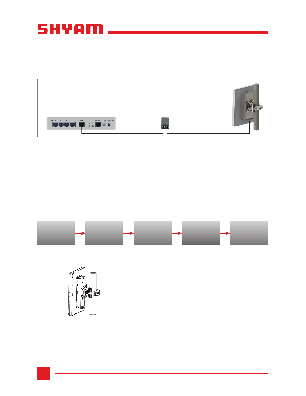
2. Installing RM24/58
Additional Hardware
• RJ-45 crimp tool (if pre-assembled cable is not used)
• Grounding cable
• 13 mm or ½½ socket spanner
• Ethernet cable - outdoor class, CAT-5e, and 4 twisted pairs
• Cable ties
• Computer/laptop running Windows XP/Windows 7
Installation Sequence
Mount RM24/58
STEP 1 Assemble RM24/58 unit onto the mast.
STEP 2 Connect the ground cable to the chassis point on RM24/58.
STEP 3 Attach cable from RM24/58 to the RJ-45 connector.
STEP 4 Secure the cables to the mast or brackets using UV-rated cable ties.
STEP 5 Repeat the procedure to mount the other RM24/58 at the slave site.
Mount
RM24/58
Ground
RM24/58
Align Master
and Slave
RM24/58
Connect
RM24/58 to
PoE Injector
Supply
Power to
PoE Injector
PoE Adapter
4-Port Switch
Integrated Antenna

NETWORKS
5
RM24/58
Ground RM24/58
STEP 1 Crimp the grounding lug at both the ends on the earthing cable.
STEP 2 Connect and tighten one end of the earthing cable to RM24/58.
STEP 3 Connect other end of the earthing cable to the earth pit on the ground.
iNote: Ensure that ground earthing is separated from power earthing.
Connect RM24/58 to PoE Injector
STEP 1 Route the cable from RM24/58 into the building where PoE injector is placed.
STEP 2 Secure the cable along its path.
STEP 3 Connect the cable from RM24/58 to the appropriate RJ-45 connector on the PoE injector.
Supply Power to PoE Injector
STEP 1 Connect the PoE adapter to the main electrical supply and the power cord
plugged into the socket of the adapter.
STEP 2 Turn on the power supply.
RM24/58 starts receiving power through the PoE adapter.
Align Master and Slave RM24/58
STEP 1 Turn on the power supply of the PoE injector at both the sites.
STEP 2 Align master RM24/58 in the direction of slave RM24/58.
STEP 3 Turn slave RM24/58 towards master site, listening to the beep sequence until
optimal alignment is achieved.
iNote: Frequent beeps indicate better signal strength. Higher signal strength has lower
pause time in between the beeps.
Frequencyofbeepconrmsthelinkquality.Thesignalstrengthimproveswith
the increase in the beep frequency. After approximately 40 seconds, the slave
RM24/58 beeper starts beeping which indicates a normal operation.
STEP 4 Tightly secure slave RM24/58 onto the mast/wall.
STEP 5 Repeat the same procedure at the master site.
Congratulations! The installation of RM24/58 is complete.
Beeper Sequence = On
= Off
Description
Indicates a good signal
Indicates a weak signal
No air link
NETWORKS
6
RM24/58
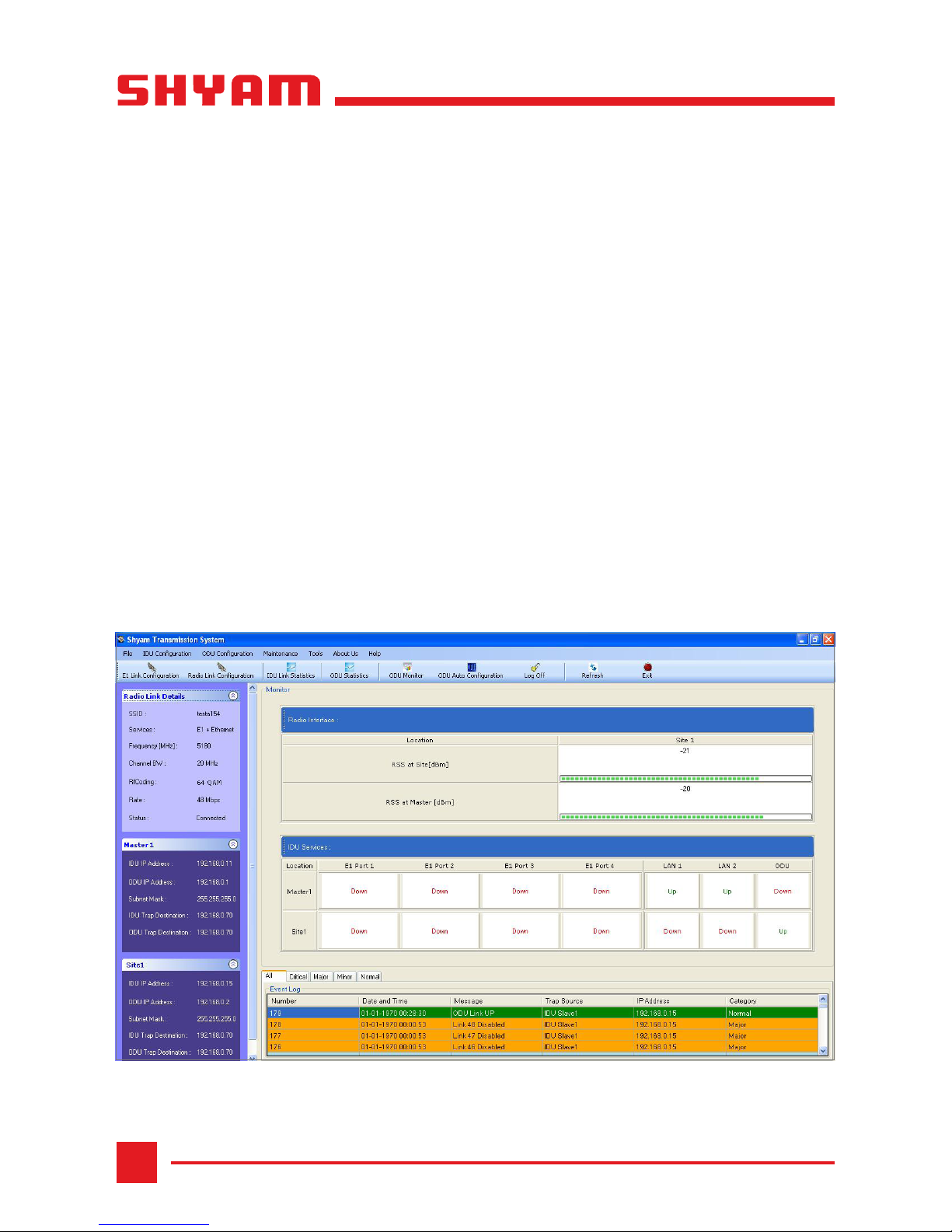
3. Configuring RM24/58
STEP 1 Install the Shyam Transmission System Management software on the system,
which on successful installation creates the Shyam Transmission System icon on
the desktop.
STEP 2 Connect the system to the LAN.
STEP 3 Double-click the Shyam Transmission System icon on the desktop or click
Start | Programs | Shyam Transmission System.
STEP 4 Enter username and password as admin.
STEP 5 Connect RM24/58 either by specifying the IP addresses or enabling the
auto-discovery option.
On successful connection, the Shyam Transmission System window appears.
Please refer to “RM-24/58 Installation and Conguration Guide” for more details.

NETWORKS
7
RM24/58
4. Quick Troubleshooting
PROBLEM PROBABLE REASON RESOLUTION
No beep sound. There is no signal. • Ensure that cable at
RM24/58 is properly
connected.
• Check the connectivity
between the external
antenna and RM24/58.
• Check master and slave
RM24/58 alignment.
• After setting to factory
defaults, check that both
master and slave sites have
same SSID and pass-phrase
for the radio link to work.
Beep sound has long
pauses in between.
The signal is weak. • Check master and slave
RM24/58 alignment.
• Check that the alignment
beeps give the best signal
beeper sequence.

NETWORKS
8
RM24/58
109.00021.00
SN/QS/RM24,58/06/11/R2.1
Warranty
This warranty is valid upto 12 months from the date of purchase.
Any manufacturing defect will be repaired by the company free of charge within the period of
warranty subject to the following conditions:
1. Thiswarrantycardmustbedulylledin,stamped&signedbythedealer.Thecardandthe
relevantcashmemomustbepreserved&producedalongwiththedefectiveunit.
2. Once the defective unit is repaired during the said warranty period, the warranty shall thereafter
continue only for the unexpired period to the original warranty.
3. This warranty is not valid in case of
• Damage resulting from accidents, mishandling, negligence, tampering, unauthorized repair,
failuretofollowinstructions,lightning,reandactofGod.
• Items not purchased from Authorized Dealers of the Company.
• Batteries (including rechargeable).
• Damage to the tamper proof seal.
• Adaptors (wherever applicable), where the Warranty is valid only up to 6 months from the date
of purchase of the product.
4. In case of a problem with your unit, please contact Customer Care. In the event that you are
advised to send and collect the unit from the Service Center of the Company – the same will be
done at your expense.
5. While Company or its Authorized Service Dealer will make every effort to carry out repairs under
this warranty as soon as possible, it is expressly made clear that the company shall not be held
liable for any direct or indirect loss to user due to delay in providing this service.
6. This warranty excludes every condition/warranty/liability not expressly set out therein.
7. Claims, if any to this warranty shall be subject to the courts having jurisdiction in Delhi, India.
Product ______________________________________________________________________
Model No. _______________________________ Serial No. ___________________________
Dealer’s Stamp & Signature Customer Care,
Shyam Networks (A Division of Vihaan Networks Ltd.)
21-B, Sec-18, Udyog Vihar, Gurgaon-122015
Haryana, India
Email: customer[email protected]
All India Helpline No. - +91 124 309 2000 Ext. 2009,
+91 9873573710
Manufactured by Vihaan Networks Ltd. Gurgaon, Haryana, India
This manual suits for next models
11
Table of contents


