Tranzeo TR-SL2 Series User manual

TRANZEO TR-SL2
Revision: 2.0
Firmware: 5.0.2
Date: 10/11/09
Tranzeo TR-SL2 Series
User Guide
Covers the following models:
TR-SL2-15, TR-SL2-N. TR-CPQ-15, TR-
CPQ-19, TR-CPQ-N

iiiiii
This document is intended for Public Distribution 19473 Fraser Way,
Pitt Meadows, B.C. Canada V3Y 2V4
ii
Document Revisions:
Version 2.0 November 10, 2009
Tranzeo Wireless Technologies Inc.
19473 Fraser Way
Pitt Meadows, BC
Canada V3Y 2V4
Toll Free Number: 1.866.872.6936
Technical Support: 1.888.460.6366 General Inquiries: info@tranzeo.com
Local Number: 1.604.460.6002 Sales: sales@tranzeo.com
Fax Number: 1.604.460.6005 Technical Support: support@tranzeo.com

iiiiiiiii
This document is intended for Public Distribution
19473 Fraser Way,
Pitt Meadows, B.C. Canada V3Y 2V4
Safety Information
iii
TR-SL2 Series
Tranzeo Wireless Technologies
This device has been tested and found to comply with the limits for a Class B digital device
pursuant to Part 15 of the FCC rules. These limits are designed to provide reasonable
protection against harmful interference when the device is operated in a residential
environment. This device generates, uses, and can radiate radio frequency energy. If not
installed and used in accordance with the user guide, may cause harmful interference to radio
communication. In case of harmful interference, the users will be required to correct the
interference at their own expense.
The users should not modify or change this device without written approval from Tranzeo
Wireless. Modification will void warranty and authority to use the device.
For safety reasons, people should not work in a situation where RF exposure limits could be
exceeded. To prevent this situation, the users should consider the following rules:
Install the antenna so that there is a minimum of 100 cm (39.37 in) of distance between
the antenna and people.
Do not turn on power to the device while installing the antenna.
Do not connect the antenna while the device is in operation.
Do not collocate or operate the antenna used with the device in conjunction with any
other antenna or transmitter.
This device has been designed to operate with the antennas listed below, and having a
maximum gain of 24 dB. Antennas not included in this list or having a gain greater
than 24 dB are strictly prohibited for use with this device. The required antenna
impedance is 50 ohms.
TR-OD24-12 –2.4 GHz 12 dBi omni
TR-24H-90-17 –2.4 GHz 17 dBi sector
TR-GD24-24 –2.4 GHz 24 dBi grid
TR-VA24-16 –2.4 GHz 16 dBi Yagi
TR-ODH24-13 –2.4 GHz 13 dBi Horizontal omni
In order to ensure compliance with local regulations, the installer MUST enter the
antenna gain at the time of installation. See Chapter 3: Wireless Settings, for details.
FCC Compliance
Safety Information
Operation of this device is subject to the following two conditions: (1) this device may not
cause interference, and (2) this device must accept any interference, including interference
that may cause undesired operation of the device.
Industry Canada Compliance

iviviv
This document is intended for Public Distribution
19473 Fraser Way,
Pitt Meadows, B.C. Canada V3Y 2V4
Safety Information
iv
TR-SL2 Series
Tranzeo Wireless Technologies
You must read and understand the following safety instructions before installing the device:
This antenna‘s grounding system must be installed according to Articles 810-15, 810
-20, 810-21 of the National Electric Code, ANSI/NFPA No. 70-1993. If you have any
questions or doubts about your antenna‘s grounding system, contact a local licensed
electrician.
Never attach the grounding wire while the device is powered.
If the ground is to be attached to an existing electrical circuit, turn off the circuit before
attaching the wire.
Use the Tranzeo Power over Ethernet (POE) adapter only with approved Tranzeo
models.
Never install radio equipment, surge suppressors or lightning protection during a storm.
! Safety Instructions
Lightning Protection
The key to lightning protection is to provide a harmless route for lightning to reach ground.
The system should not be designed to attract lightning, nor can it repel lightning. National,
state and local codes are designed to protect life, limb, and property, and must always be
obeyed. When in doubt, consult local and national electrical codes or contact an electrician or
professional trained in the design of grounding systems.
The product requires professional installation. Professional installers ensure that the
equipment is installed following local regulations and safety codes.
Professional Installation Required

vvv
This document is intended for Public Distribution
19473 Fraser Way,
Pitt Meadows, B.C. Canada V3Y 2V4
Table of Contents
v
TR-SL2 Series
Tranzeo Wireless Technologies
Chapter 1: Overview ........................................................................ 1-1
Introduction ......................................................................................................1-1
Product Kit........................................................................................................1-1
Product Description ..........................................................................................1-1
LED Panel Indicators...................................................................................1-2
Chapter 2: Hardware Installation...................................................... 2-1
Getting Ready...................................................................................................2-1
Tools Required.............................................................................................2-1
Site Selection ...............................................................................................2-1
Polarity.........................................................................................................2-2
Power Supply...............................................................................................2-2
Installing the Ethernet Cable ............................................................................2-3
Mounting the Radio..........................................................................................2-5
Grounding the Antenna ....................................................................................2-5
Connecting the Radio .......................................................................................2-6
Best Practices....................................................................................................2-7
Chapter 3: Configuration................................................................... 3-1
Connecting to the Radio ...................................................................................3-1
Changing the IP Address - Windows XP ....................................................3-1
Changing the IP Address Using the Tranzeo Victor Program.....................3-2
Login into the Configuration Interface.............................................................3-4
Information Page ..............................................................................................3-5
Setup Menu.......................................................................................................3-6
Wireless Settings - Basic Tab .....................................................................3-6
Wireless Settings - Advanced Tab..............................................................3-8
Administrative Settings - Firmware Tab ....................................................3-9
Administrative Settings - Import / Export Tab ...........................................3-10
Administrative Settings - SNMP Tab .........................................................3-11
Security...........................................................................................................3-12
WEP Settings .............................................................................................3-12
WPA Settings............................................................................................. 3-13
Status ..............................................................................................................3-14
AP List .......................................................................................................3-14
ARP Table ................................................................................................. 3-14
Statistics.....................................................................................................3-15
Table of Contents

vivivi
This document is intended for Public Distribution
19473 Fraser Way,
Pitt Meadows, B.C. Canada V3Y 2V4
Table of Contents
vi
TR-SL2 Series
Tranzeo Wireless Technologies
Wireless Performance................................................................................3-17
System Performance ..................................................................................3-18
Network Configuration...................................................................................3-19
Bridge Mode - Static.................................................................................3-19
Bridge Mode - DHCP Client ....................................................................3-20
Router Mode ..............................................................................................3-21
Router Mode - PPPoE...............................................................................3-22
Networking Advanced - Bridge Mode .....................................................3-23
Networking Advanced - Router Mode .....................................................3-24
DHCP Configuration .................................................................................3-25
IP Routing..................................................................................................3-26
Shaping and Quality of Service Configuration (QoS)...............................3-27
Port Forwarding ......................................................................................... 3-29
IP Filtering ................................................................................................. 3-30
Appendix A: Grounding and Lightning Protection Information .... A-1
Appendix B: Quality of Service Configuration (QoS) ..................... B-1
Appendix C: Protocol List................................................................. C-1
Appendix D: Common TCP Ports..................................................... D-1
Appendix E: Channel Allocations .................................................... E-1
Appendix F: Wiring Standard ........................................................... F-1
Appendix G: Routing Quick Start Guide.......................................... G-1
Appendix H: PxP Install Checklist.................................................... H-1
Appendix I: Glossary of Terms......................................................... I-1
Appendix J: AutoConfig.................................................................... J-1
Appendix K: Tranzeo Electrical Plugs ............................................. K-1
Appendix L: Warranty Terms............................................................ L-1
Appendix M: How Can We Improve? ............................................... M-1
Appendix N: Notes ............................................................................. N-1
111
This document is intended for Public Distribution
19473 Fraser Way,
Pitt Meadows, B.C. Canada V3Y 2V4
Chapter 1: Overview
1-1
TR-SL2 Series
Tranzeo Wireless Technologies
Introduction
This next-generation wireless LAN device–the Tranzeo TR-SL2 series–brings
Ethernet-like performance to the wireless realm. Fully compliant with the
IEEE802.11a standard, the TR-SL2 series also provides powerful features such as
the Internet-based configuration utility as well as WEP and WPA security.
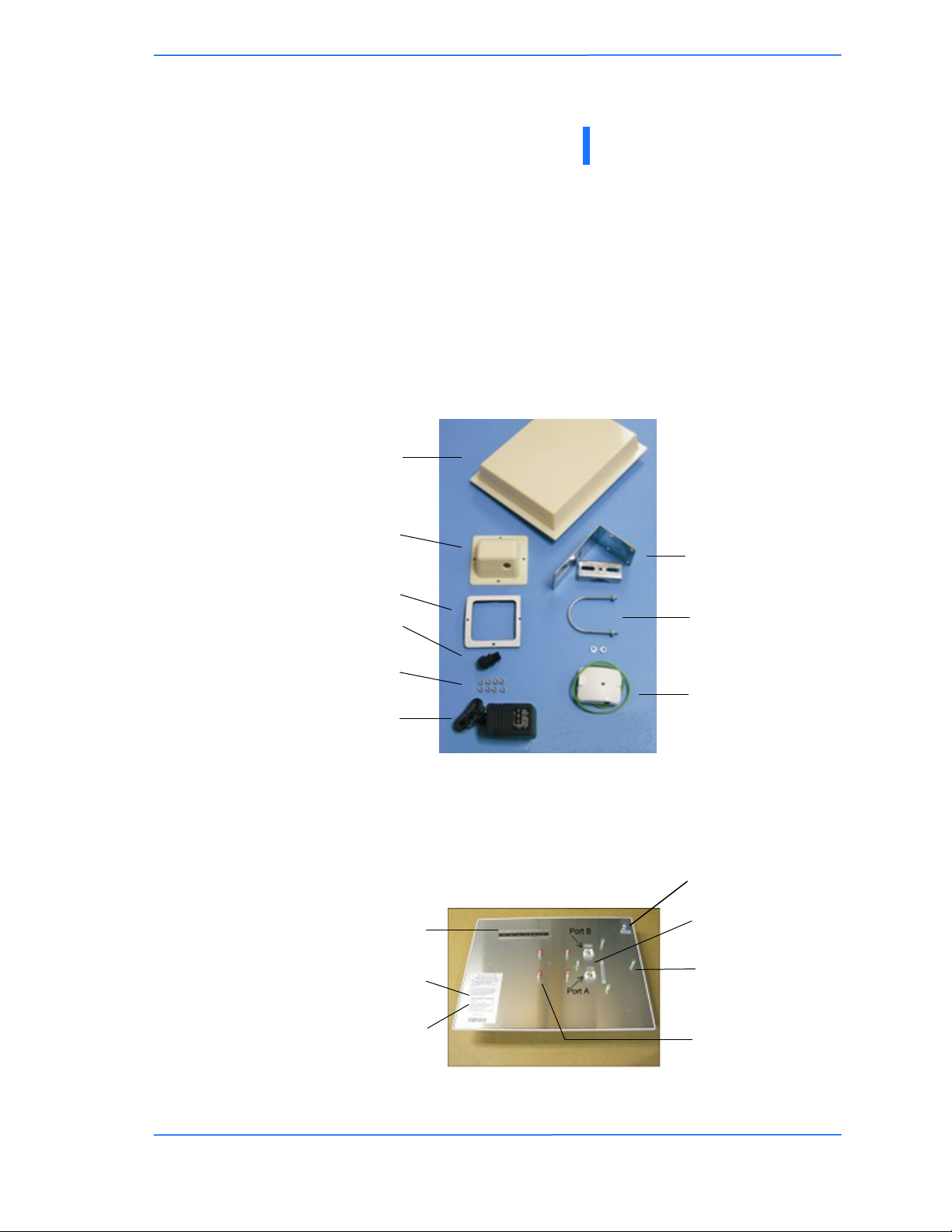
Product Kit
The TR-SL2 Series product kit contains the items shown below. If any item is
missing or damaged, contact your local dealer for support.
Product Description
The LEDs, ports and product information are located at the back of the TR-SL2
Series radio, as shown in the picture.
Chapter 1: Overview
DC power
adapter x 1
3/8‖ x 10/32 Kep nuts x 8
TR-SL2 Series device x 1
Ethernet boot cover x 1
Gasket x 1
3/4‖ Strain relief x 1
Mounting bracket x 1
Saddle x 1
U-bolt x 1
with 2 1/2‖ nuts
POE adapter x 1
LED Panel indicators
MAC address
Ethernet ports
Serial number
Studs for the boot
cover
Studs for the
mounting bracket
Grounding Lug

222
This document is intended for Public Distribution
19473 Fraser Way,
Pitt Meadows, B.C. Canada V3Y 2V4
Chapter 1: Overview
1-2
TR-SL2 Series
Tranzeo Wireless Technologies
LED Panel Indicators
Operational Color Indicators
Power ● Red On: Powered on
Off: No power or LED’s Disabled
LAN ● Red
On: Ethernet link
Flashing: Ethernet traffic
Off: No Ethernet link
Radio ● Red
On: Radio link
Flashing: Radio activity
Off: No radio link
Signal
In CPE mode
LEDS light up
in sequence
to indicate
signal
strength
based on
Signal -
Noise.
●Amber 1 to 10 db above noise
●Amber 11 to 15 db above noise
●Amber 16 to 20 db above noise
●Amber 21 to 30 db above noise
●Amber 31 or more db above noise
111
This document is intended for Public Distribution
19473 Fraser Way,
Pitt Meadows, B.C. Canada V3Y 2V4
Chapter 2: Hardware Installation
2-1
TR-SL2 Series
Tranzeo Wireless Technologies
The TR-SL2 Series radios are easy to install, as you‘ll see in this chapter. Before
starting, you will need to get the tools listed below and decide about the site and
orientation of the device. Once ready, follow the instructions about how to install
the Ethernet cable, mount the device, ground the antenna, and make the
connections in order to get a proper installation.
Getting Ready
Tools Required
To install your TR-SL2 Series radio you will need the following tools:
1/2‖ wrench x 1
3/4‖ wrench x 1
3/8” wrench x 1
Cat 5 cable stripper x 1
Cat 5 cable (to connect the radio to the POE adapter)
RJ-45 patch cable
RJ-45 crimper x 1
RJ-45 connectors x 4
#6 green grounding wire
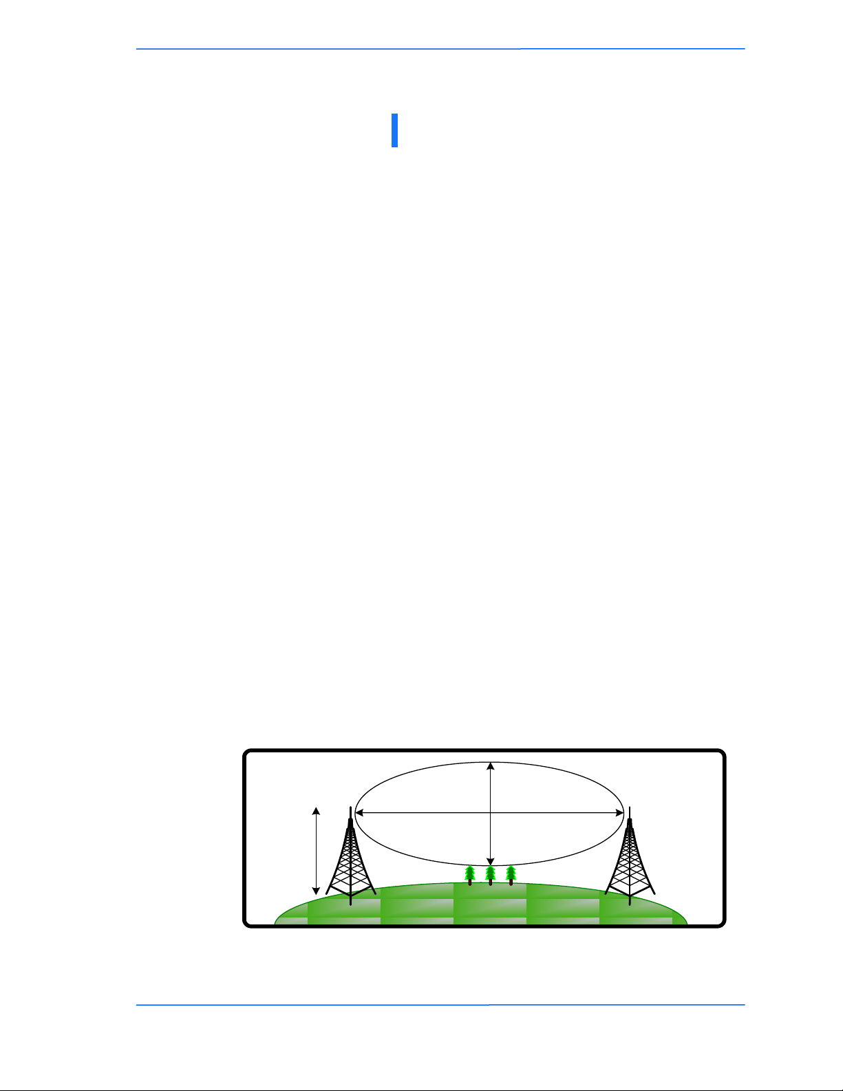
Site Selection
Determine the location of the radio before installation. Proper placement of the
device is critical to ensure optimum radio range and performance. You should
perform a site survey to determine the optimal location.
Ensure the CPE is within line-of-sight of the access point. The line-of-sight is an
ellipse, called Fresnel zone. This zone should be clear of obstacles since
obstructions will impede performance of the device.
Fresnel zone
Chapter 2: Hardware Installation
Antenna
Height
r = radius
d = distance

222
This document is intended for Public Distribution
19473 Fraser Way,
Pitt Meadows, B.C. Canada V3Y 2V4
Chapter 2: Hardware Installation
2-2
TR-SL2 Series
Tranzeo Wireless Technologies
Polarity
Determine if the antenna‘s polarization will be horizontal or vertical before
installation. The TR-SL2 radios can be used in either polarity. The Ethernet boot
cover should always be placed so that the cable runs toward the ground for
maximum environmental protection.
Power Supply
Only use a power adapter approved for use with the TR-SL2 Series radio.
Otherwise, the product may be damaged and will not be covered by the Tranzeo
warranty.
333
This document is intended for Public Distribution
19473 Fraser Way,
Pitt Meadows, B.C. Canada V3Y 2V4
Chapter 2: Hardware Installation
2-3
TR-SL2 Series
Tranzeo Wireless Technologies
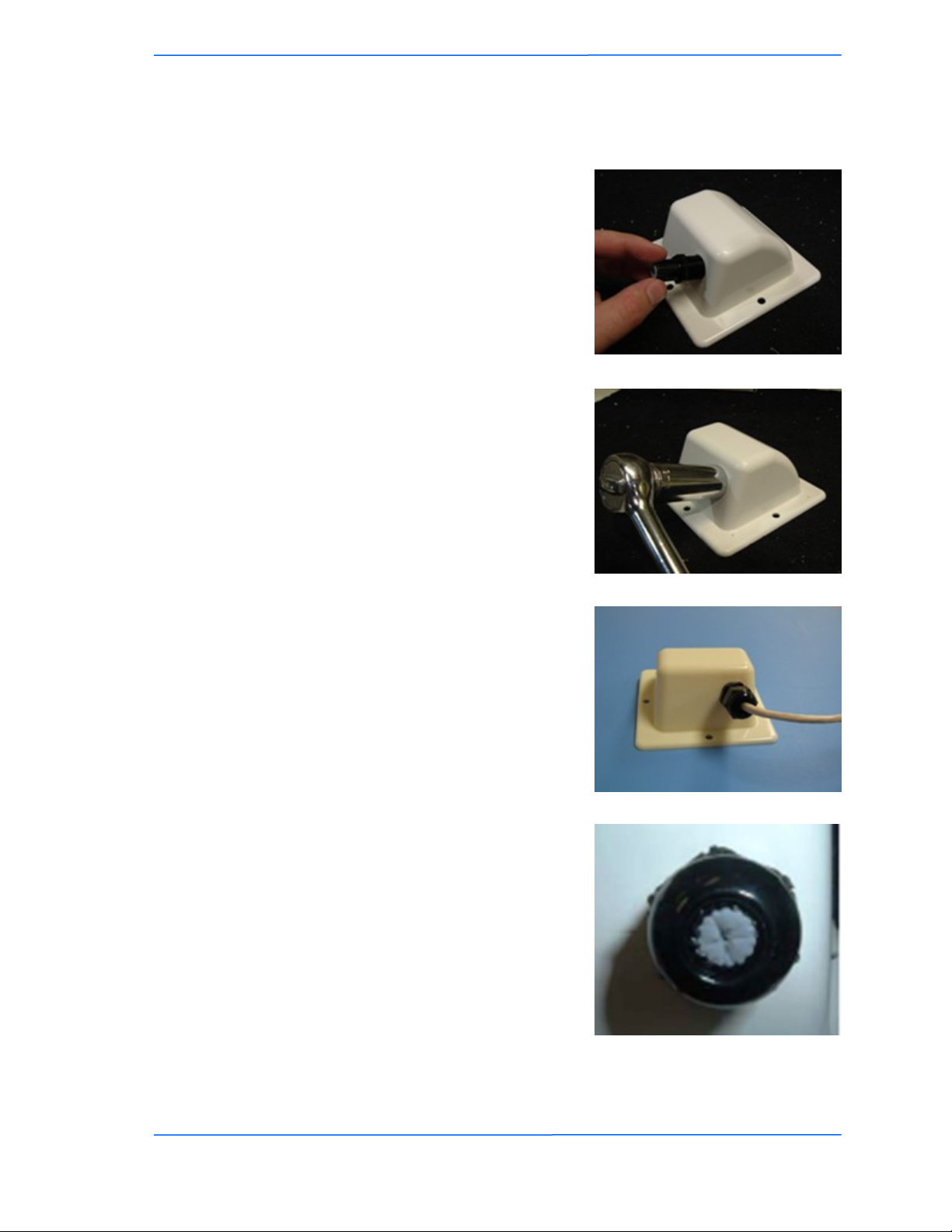
Installing the Ethernet Cable
Step 2:
Using a 3/4‖ wrench, tighten the strain
relief until it touches the boot cover.
IMPORTANT! Use hand tools only. Do
not over tighten.
Step 3:
Put the cap nut back over the strain relief
and insert the Cat 5 cable through it. Wire
the cable following the EIA/TIA T568B
standard, and attach the RJ-45 connectors
to each end of the cable. (See Appendix F:
Wiring Standard).
Step 1:
Insert the strain relief, without the cap nut,
into the port opening of the boot cover.
Step 4:
If you purchased the device with a dual
port cover, repeat steps 1, 2, and 3 for the
second port.
IMPORTANT! If you are not going to use
the second port, insert the strain relief into
the boot cover and tighten the cap nut to
ensure a weather-tight seal, as shown in
the picture.

444
This document is intended for Public Distribution
19473 Fraser Way,
Pitt Meadows, B.C. Canada V3Y 2V4
Chapter 2: Hardware Installation
2-4
TR-SL2 Series
Tranzeo Wireless Technologies
Step 7:
Fit the boot cover over the 4 studs and the
gasket. Secure with 4 keps nuts. Tighten
with a 3/8‖ wrench until the gasket is at
least 50% compressed.
Step 5:
Place the gasket—with the adhesive side
facing up—over the 4 studs around the port
of the radio. Flatten the gasket ensuring
there are no gaps. Remove the backing.
Step 8:
Make sure the cap nut of the strain relief is
tightened properly to ensure a weather-
proof seal.
IMPORTANT! Hand tighten only. Do not
over tighten as you may damage the
weather-tight seal of the strain relief.
Step 6:
Plug the Cat 5 cable inserted in the boot
cover into the port. Remember to place the
boot cover according to the desired
polarization, so that the strain relief faces
the ground.

555
This document is intended for Public Distribution
19473 Fraser Way,
Pitt Meadows, B.C. Canada V3Y 2V4
Chapter 2: Hardware Installation
2-5
TR-SL2 Series
Tranzeo Wireless Technologies
Mounting the Radio
Step 9:
Attach the mounting bracket to the pole
using the U-bolt. Secure the U-bolt with
the lock washers and the nuts. Align if
necessary, and then tighten the nuts enough
to prevent any movement.
Step 10:
Fit the radio to the mounting bracket.
Secure the radio with keps nuts.
IMPORTANT! The strain relief must be
always facing the ground.
Grounding the Antenna
Step 11:
Using a #6 green grounding wire, connect
the grounding lug on the radio to a proper
ground. See Appendix A: Grounding and
Lighting Protection Information.
IMPORTANT: This device must be grounded. Connect the green grounding wire
to a known good earth ground, as outlined in the National Electrical Code. See
Appendix A: Grounding and Lightning Protection Information for details.
!
666
This document is intended for Public Distribution
19473 Fraser Way,
Pitt Meadows, B.C. Canada V3Y 2V4
Chapter 2: Hardware Installation
2-6
TR-SL2 Series
Tranzeo Wireless Technologies
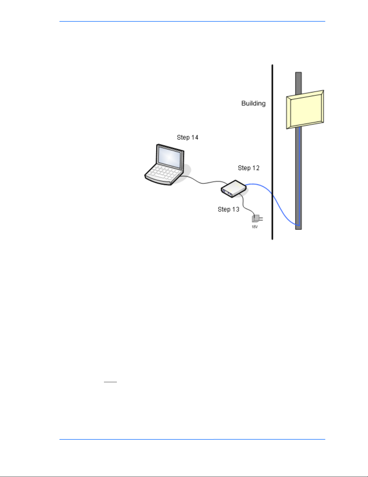
Connecting the Radio
Step 14:
To configure the TR-SL2 Series radio,
connect the Ethernet cable to the POE
adapter and to a computer. Ensure that the
distance between the computer and the
radio does not exceed 300 ft (90 m).
Note: If connecting to a hub or switch, a
crossover cable may be required.
IMPORTANT! Use the power adapter
supplied with the radio. Otherwise, it may
be damaged.
Step 12:
Connect the Cat 5 cable from the radio into
the RJ-45 jack marked ―CPE‖ on the POE
adapter. The POE adapter is not weather-
proof and should be installed indoors.
Step 13:
Connect the power adapter to the POE
adapter and plug the other end to an outlet.
The POE adapter will be powered on and
the power indicator on the top panel will
turn on. We recommend connecting the
power adapter to an outlet with surge
suppression capability with an uninterrupted
power supply (UPS) for reduced outages.

777
This document is intended for Public Distribution
19473 Fraser Way,
Pitt Meadows, B.C. Canada V3Y 2V4
Chapter 2: Hardware Installation
2-7
TR-SL2 Series
Tranzeo Wireless Technologies
Best Practices
Follow these practices to ensure a correct installation and grounding.
Always try to run long Cat 5 and LMR cables inside of the mounting pole.
This helps to insulate the cable from any air surges.
Keep all runs as straight as possible. Never put a loop into the cables.
Test all grounds to ensure that you are using a proper ground. If using an
electrical socket for ground, use a socket tester, such as Radio Shack 22-141.
Keep a copy of the National Electrical Code Guide at hand and follow its
recommendations.
If you are in doubt about the grounding at the location, drive your own rod
and bond it to the house ground. At least you will know that one rod is
correct in the system.
111
This document is intended for Public Distribution
19473 Fraser Way,
Pitt Meadows, B.C. Canada V3Y 2V4
Chapter 3: Configuration
3-1
TR-SL2 Series
Tranzeo Wireless Technologies
The TR-SL2 Series radios can be configured through an HTML configuration
interface, accessible using any Internet browser. The configuration interface
allows you to define and change settings, and also shows information about the
performance of the device.
In this chapter we‘ll cover how to access the configuration interface, configure the
TR-SL2 Series radio, and interpret the information displayed in the interface.
Depending on whether the device is defined as an AP or CPE (infrastructure
station), some menu options, windows, and fields in the interface may vary or may
not appear at all. We‘ll indicate so when describing each window.
Connecting to the Radio
Before accessing the configuration interface, you have to change the network
connection settings in your computer to be on the same subnet as the radio.
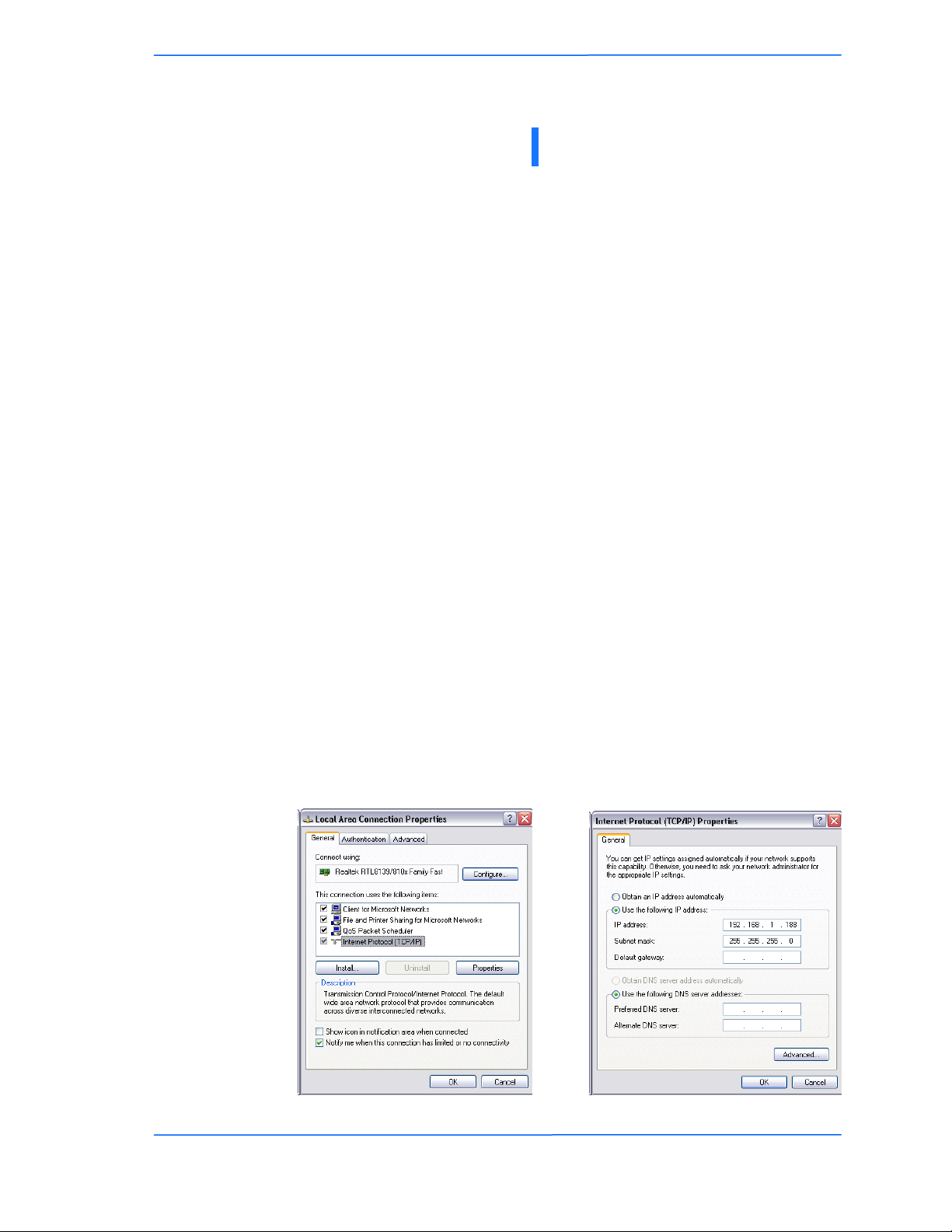
Changing the IP Address - Windows XP
1. In your computer, open Control Panel > Network Connections > Local Area
Connection.
2. In Local Area Connection Status > General, click Properties.
3. In Local Area Connection Properties > General, select Internet Protocol
(TCP/IP) and click Properties.
4. In Internet Protocol (TCP/IP) Properties > General, select Use the following
IP address.
5. Enter your IP address and Subnet Mask. The default IP address of the radio
is 192.168.1.100, which cannot be used here.
6. Click OK and Close.
Chapter 3: Configuration
222
This document is intended for Public Distribution
19473 Fraser Way,
Pitt Meadows, B.C. Canada V3Y 2V4
Chapter 3: Configuration
3-2
TR-SL2 Series
Tranzeo Wireless Technologies
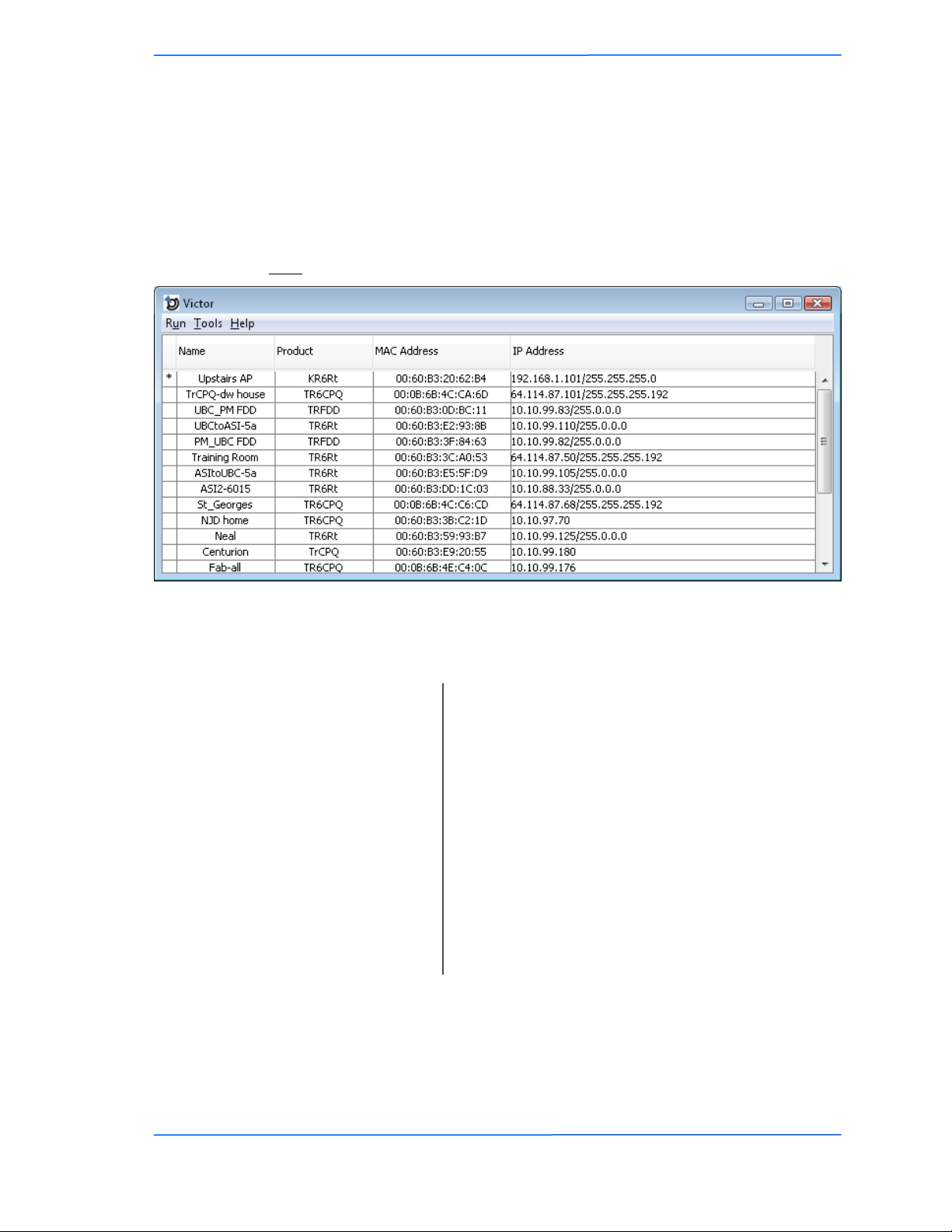
Changing the IP Address Using the Tranzeo Victor Program
The Tranzeo Victor Program is a utility that allows users to quickly change the IP
address of the Tranzeo radios. It sends out a broadcast on the network and displays
a list of other Tranzeo radios connected, from which you can configure the IP
address for your device.
Note: The Tranzeo Victor Program cannot locate radios through routers.
Columns
The Tranzeo Victor Program has a number of menu options.
Name: Displays the Device Name as set in the Administrative
Options Page of the HTTP Interface
Product: Display the Tranzeo Product Name. This is a read
only Value.
Mac Address: Displays the MAC address the device is current using.
If the MAC Cloning option has been turned on, the
MAC Address that appears is as set in the Network
Interface. If the MAC Cloning feature has not been
used, then the Factory set MAC Address appears.
IP Address: Displays the Ip Address and Netmask as set in the
Network Page of the HTTP Interface
.

333
This document is intended for Public Distribution
19473 Fraser Way,
Pitt Meadows, B.C. Canada V3Y 2V4
Chapter 3: Configuration
3-3
TR-SL2 Series
Tranzeo Wireless Technologies
RunMenu
Tools Menu
Help Menu
The About option displays the Version Number of the Program.
Scan: Locates Tranzeo radios connected to the network. A *
appears before the name when the radio is in the same
subnet as your PC.
Detail: Displays more info for a selected radio, such as IP
Mode, Gateway, etc .This option is only available
when a device is selected.
Set IP: Using this option you set the device to have a DCHP
address, or set the Static Details.
Disabling Locator Write Access under the
Administrative Settings page of the HTTP interface
will cause the device to not accept these changes.
This option is only available when a device is selected.
Reset: Reboots the radio. This option is only available when
a device is selected.
Quit: Exits the program.
Open Browser: Opens the HTTP page of the selected device in the
Web Brower.
Options: Allows you to adjust some the Program‘s settings
Scan Timeout: Sets the amount of time the program will wait for
Scan results. Increase this value if you find that not
every radio is being found.
Request Timeout: Sets the amount of time the program will wait for
Detail results. Increase this value if you find that
Detail requests are timing out.
Web Browser: Victor uses the system browser by default. IF you
wish to use an alternative browser to access your
Tranzeo Radios, enter the full path to the alternative
browser here.
Protocol: The TR-SL2 Series use the Legacy protocol.
Tranzeo‘s WiMAX, EL, EN and many other series of
Radios use the newer TDP (Tranzeo Discovery
Protocol).
Scan when Start: Enables the automatic Scan when the program is
started.
444
This document is intended for Public Distribution
19473 Fraser Way,
Pitt Meadows, B.C. Canada V3Y 2V4
Chapter 3: Configuration
3-4
TR-SL2 Series
Tranzeo Wireless Technologies
Login into the Configuration Interface
After defining the network settings, follow these steps to login into the Tranzeo
Configuration Interface.
1. Open your Internet browser (Internet Explorer, Netscape, or Firefox).
2. In the address bar, type your IP address (default IP: http://192.168.1.100).
3. In the login dialog, enter your Username and Password (if you‘re a first-
time user, follow the instructions below).
4. Click OK. You will then access the configuration interface.
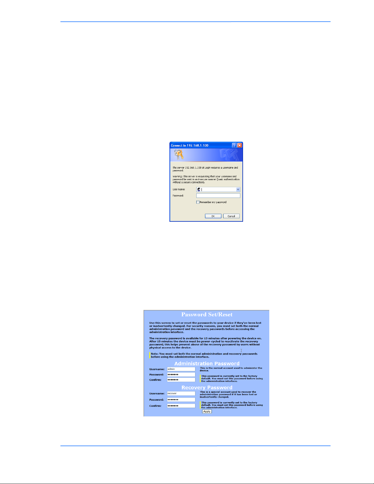
If you‘re a first-time user:
1. Enter the default username admin and the default password default.
2. In the Password Set/Reset window, change the Administration and
Recovery*passwords. They cannot be left as default and must be different
from each other. You can change the usernames too.
3. Click Apply to save the changes.
4. You will be prompted to enter your new username and password in the login
dialog. You will then access the configuration interface.
* The recovery username and password are used to access the Password Set/Reset
window if the administration password is lost.

555
This document is intended for Public Distribution
19473 Fraser Way,
Pitt Meadows, B.C. Canada V3Y 2V4
Chapter 3: Configuration
3-5
TR-SL2 Series
Tranzeo Wireless Technologies
Information Page
This is the first window of the configuration interface. It shows the main menu and
information about the device settings, like wireless, network, and security settings.
The menu is divided in four sections:
Setup Menu
Security
Status
Network
Each section contains navigation links to the configuration windows.
Information Page - CPE
This manual suits for next models
5
Table of contents
Other Tranzeo Radio manuals

Tranzeo
Tranzeo TR-5A Series User manual

Tranzeo
Tranzeo TR-Multi-N User manual

Tranzeo
Tranzeo TR-6015f User manual

Tranzeo
Tranzeo TR-902 Series User manual

Tranzeo
Tranzeo TR-6015 User manual

Tranzeo
Tranzeo TR-900 Series User manual

Tranzeo
Tranzeo TR-5A Series User manual

Tranzeo
Tranzeo tr-5plus series User manual

Tranzeo
Tranzeo TR-49 Series User manual


