Siabs 4P User manual

via Del Lavoro, 7 Fax +39 02 9029538 Web page www.siabs.com
20010 – Casorezzo (MILAN)
Luminous Infra-red Gas Heaters
MANUAL for INSTALLATION,
RUNNING and MAINTENANCE
Models: 4P, 6P, 8P, 10P, 12PR, 12P, 16P,
4PB, 6PB, 8PB, 10PB, 12PRB, 12PB, 16PB,
10+10P, 12+12P, 16+16P,
10+10PB, 12+12PB, 16+16PB,
10+10PS, 12+12PS, 16+16PS
10+10PSB, 12+12PSB, 16+16PSB
Version “DC and DCeco”

Manu_ENG_DC_DCeco_rev. 0_04_2012 page 2
CONTENT
General instruction 3
For Your safety 4
Warranty terms 4
Labels 5
. plate with technical data 5
. packing label 5
Technical data 6
. appliances version DC and version DCeco 6
Installation 7 to 19
. ventilation 7
. positioning 8 and 9
. handling 9
. MINIMUM height of installation (for people comfort) 10
. MINIMUM distances (from flammable surfaces) 11
. connection to GAS supply 12
. connection to ELECTRIC feeding 13
. SIT control unit, wiring diagram, ON-OFF version 14
. SIT control unit, TWO-STAGE version 15 and 16
. SIT control unit, wiring diagram, TWO-STAGE version 17
. gas group (gas valve and flame control), possible alternatives 18 and 19
Put in operation and First Start-up 20
. appliances version DC and version DCeco 20
Maintenance and Annual Check 21
. ordinary maintenance (suggestions) 21
. nozzle replacement 22
. trouble shooting 23
. serial number (bars code) 23
SPARE-PARTS, suggested list 24
Decommissioning and disposal (norms for user) 25
CE certificate 26
Service sheet 27

Manu_ENG_DC_DCeco_rev. 0_04_2012 page 3
GENERAL INSTRUCTIONS for INSTALLER,
USER and MAINTENANCE PERSONNEL
Thank you for your preference and trust granted! SIABS is pleased to have You among
his Customers; our appliances are designed and manufactured to the most modern and
rational processing systems and we do think that their use will be fully satisfactory.
To keep appliances perfectly working and safe, time passing, we invite you to read and
follow the instructions of this handbook and commit all installation and maintenance
(ordinary and extraordinary) operations only to skilled personnel, with specific
technical skills in the field of components of heating, preferably to SIABS authorized Service
Centre.
For the INSTALLER:
-read carefully the warnings in the manual before performing any operation
as they provide important information concerning the safety of installation, use and
the necessary maintenance operations to be performed
-this manual is integral and essential part of the product and must be delivered to
the user; retain it carefully for further consultations
-in case of non-compliance with the following instructions, the warranty
covering the product(s) will be null and void
-BEFORE THE INSTALLATION, verify that local gas distribution (type of gas and
pressure) and appliance settings are compatible
-appliance must be installed only in premises with adequate ventilation
-installation should be done in accordance with the Regulations in force in the
country of destination, to the state of art, following instructions by the Manufacturer
-incorrect installation can cause damage to people, animals and things; the
Manufacturer doesn’t accept any contractual and extra-contractual liability in tort
and contract for damages caused by errors in installation and use
-use only original accessories and modification kits
-after you have removed all items from packing box, make sure that all
components have been included and their integrity, in case of doubt not use
the appliance and contact the Manufacturer; elements of packaging are potentially
dangerous: therefore should not be left within the reach of children and must be
disposed according to regulations in force
-before any cleaning or maintenance operation, wait until the appliance is cold,
disconnect it from the electricity supply and bring the fuel shut-off valve in
the closed position
For the USER and OWNER of the plant:
-this manual is integral and essential part of the product and must be delivered to
the user; retain it carefully for further consultations
-in case of non-compliance with the following instructions, the warranty
covering the product(s) will be null and void
-use only original accessories and modification kits
-in case of failure and/or malfunction of the appliance, turn it off refraining from any
attempt to repair or direct intervention; contact SIABS authorized Service
Centre
-when you decide to stop using the appliance, for DISPOSAL or RESALE, you will
have to render harmless all parties which can be a source of potential danger; the
technical manual is integral and essential part of the product: it must be
preserved and accompany the appliance in case of property change, so that
it can be consulted by the new user and / or maintenance staff

Manu_ENG_DC_DCeco_rev. 0_04_2012 page 4
FOR YOUR SAFETY
IMPORTANT: appliances MUST NOT be used in domestic environments. This appliance
will be devoted only to the use for which it was expressly provided, all other uses will be
considered improper and therefore dangerous.
IMPORTANT: appliances MUST NOT be used in ambient with flammable materials,
liquids or vapours: non-compliance with these requirements may be cause of death, injury
to persons or damage to things.
Warranty
SIABS guarantees its products, whether installed by authorized personnel, for a period of 24
months from the invoice date. The warranty does not cover the components supplied by third
parties, these are subject to the conditions of the original warranty.
The guarantee is only the free supply on Ex-Works basis, of parts with manufacturing or
workmanship defects.
The guarantee does not cover problems due to carelessness, incorrect setting, misuse of the
appliance or fortuitous accidents, and not dependent on imperfection processing or defective
materials, and those due to dismantling or changes without prior authorization from SIABS.
The correct functioning of the appliances depends on a proper installation and start-up. Failure
to comply with these rules immediately involves the decay of the guarantee, and therefore of
responsibility by the manufacturer.
In case of gas smell: DO NOT operate the heating plant, vent the ambient,
DO NOT start apparatus or electric switches; contact the installer and gas
supply company and follow scrupulously their instruction

Manu_ENG_DC_DCeco_rev. 0_04_2012 page 5
Plate label
On each unit you will find a plate with technical data – do not remove – placed on the head of
the appliance (version DC) or on the reflectors (version DCeco).
Apparatus type A1, gas category II 2H3P
Plate label (example: appliance 16+16PB, version DC, two-stages, G20 natural gas)
Essential features of the appliance are given on the packing label, outside on the packing box.
Manu_ENG_DC_DCeco_rev. 0_04_2012 page 6
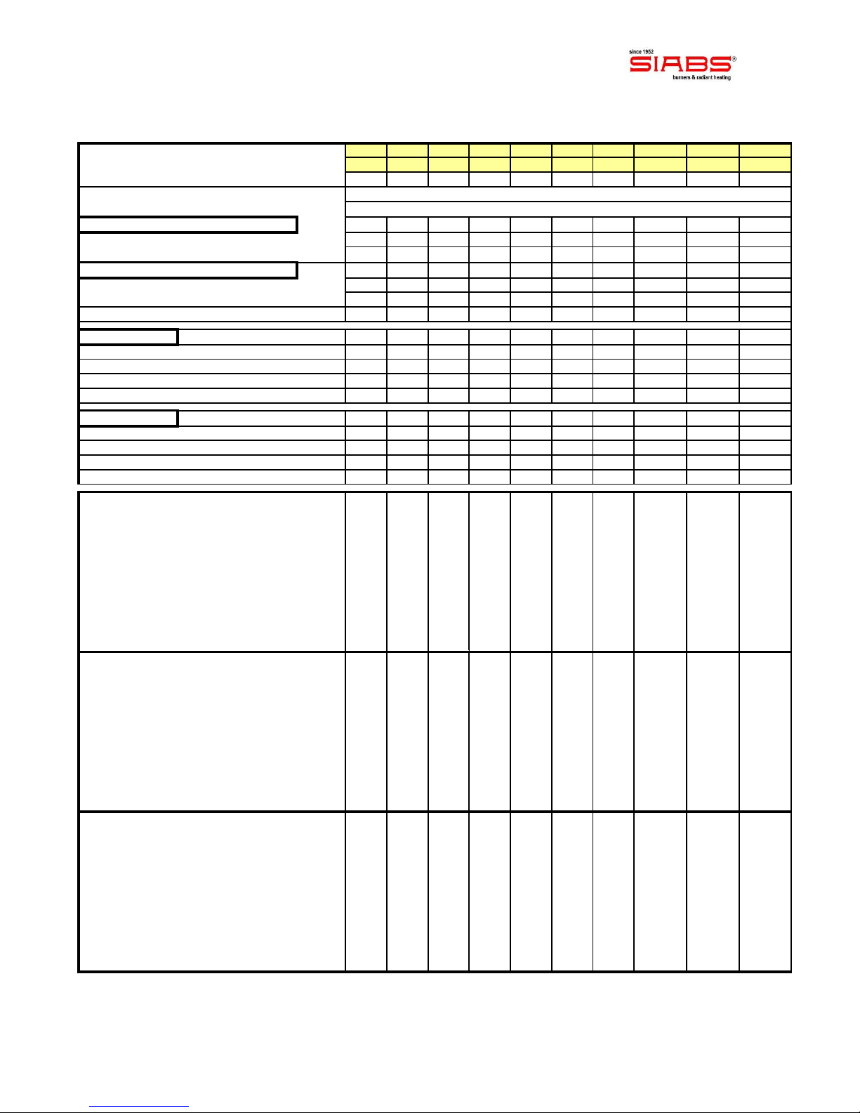
TECHNICAL DATA
Appliance model, ON-OFF version 4P 6P 8P 10P 12PR 12P 16P 10+10P 12+12P 16+16P
Appliance model, TWO-STAGES version 4PB 6PB 8PB 10PB 12PRB 12PB 16PB 10+10PB 12+12PB 16+16PB
Ceramic plates nr. 4 6 8 10 12 12 16 2 x 10 2 x 12 2 x 16
Electric feeding 230 Volt - singlephase - 50 Hz
MAX feeding pressure (mbar) 50.0
Gas group, type P, PR, PB and PRB nr. 1111111 2 2 2
Gas connection 1 x 1/2" 1 x 1/2" 1 x 1/2" 1 x 1/2" 1 x 1/2" 1 x 1/2" 1 x 1/2" 1 x 3/4" 1 x 3/4" 1 x 3/4"
Absorbed power (Watt) 24 24 24 24 24 24 24 2 x 24 2 x 24 2 x 24
Gas group, type PS and PSB nr. - - - - - - - 1 1 1
Gas connection - - - - - - - 1 x 1/2" 1 x 1/2" 1 x 1/2"
Absorbed power (Watt) - - - - - - - 1 x 24 1 x 24 1 x 24
NOxclass 4444444 4 4 4
V
ersion DC Weight (kg) 13 16 19 21 25 25 31 37 44 52
Length (mm) 420 605 790 980 1160 1160 1530 980 1160 1530
Gas group (mm) 250 250 250 250 250 250 250 300 300 300
Width (mm) 465 465 465 465 465 465 465 710 710 710
Height (mm) 350 350 350 350 350 350 350 350 350 350
V
ersion DCeco Weight (kg) 8 10 12 14 17 17 21 29 34 40
Length (mm) 420 605 790 980 1160 1160 1530 980 1160 1530
Gas group (mm) 250 250 250 250 250 250 250 300 300 300
Width (mm) 375 375 375 375 375 375 375 600 600 600
Height (mm) 250 250 250 250 250 250 250 250 250 250
GAS G20
Heat input MAX (Hs) (kW) 7,2 9,6 16,1 18,3 19,0 22,2 34,4 36,6 44,4 68,8
Heat input MAX (Hi) (kW) 6,5 8,6 14,5 16,5 17,1 20,0 31,0 33,0 40,0 62,0
Heat input MIN (Hs) (kW) 5,4 7,2 12,1 13,8 14,2 16,7 31,1 27,6 33,4 62,2
Heat input MIN (Hi) (kW) 4,9 6,5 10,9 12,4 12,8 15,0 28,0 24,8 30,0 56,0
GAS supply pressure (mbar) 20,0 20,0 20,0 20,0 20,0 20,0 20,0 20,0 20,0 20,0
NOZZLE pressure MAX (mbar) 15,5 14,0 14,0 15,0 13,5 16,0 14,0 15,0 16,0 14,0
NOZZLE pressure MIN (mbar) 8,5 7,5 8,0 9,0 7,5 9,5 10,5 9,0 9,5 10,5
Gas consumption MAX
(
Sm3
/
h
)
0,69 0,91 1,53 1,75 1,81 2,12 3,43 3,50 4,24 6,70
Gas consumption MIN
(
Sm3
/
h
)
0,52 0,69 1,15 1,31 1,35 1,59 2,95 2,62 3,18 5,90
Nozzle diameter (mm) 2,10 2,45 3,10 3,30 3,40 3,50 4,50 2 x 3,30 2 x 3,50 2 x 4,50
GAS G30
Heat input MAX (Hs) (kW) 7,0 9,3 13,5 17,9 17,8 21,7 33,6 35,8 43,4 67,2
Heat input MAX (Hi) (kW) 6,5 8,6 12,5 16,5 16,5 20,0 31,0 33,0 40,0 62,0
Heat input MIN (Hs) (kW) 5,3 7,0 10,2 13,4 15,7 16,3 27,1 26,8 32,6 54,2
Heat input MIN (Hi) (kW) 4,9 6,5 9,4 12,4 14,5 15,0 25,0 24,8 30,0 50,0
GAS supply pressure (mbar) 30,0 30,0 30,0 30,0 30,0 30,0 30,0 30,0 30,0 30,0
NOZZLE pressure MAX (mbar) 28,2 28,0 28,0 28,5 28,0 28,1 27,6 28,5 28,1 27,6
NOZZLE pressure MIN (mbar) 16,5 16,0 15,5 16,0 23,0 16,0 18,0 16,0 16,0 18,0
Gas consumption MAX (kg/h) 0,51 0,68 0,99 1,30 1,30 1,58 2,42 2,60 3,16 4,84
Gas consumption MIN (kg/h) 0,39 0,51 0,74 0,98 1,14 1,18 1,96 1,96 2,36 3,91
Nozzle diameter (mm) 1,30 1,50 1,80 2,10 2,10 2,30 2,80 2 x 2,10 2 x 2,30 2 x 2,80
GAS G31
Heat input MAX (Hs) (kW) 7,0 9,3 13,5 17,9 17,8 21,7 33,6 35,8 43,4 67,2
Heat input MAX (Hi) (kW) 6,5 8,6 12,5 16,5 16,5 20,0 31,0 33,0 40,0 62,0
Heat input MIN (Hs) (kW) 5,3 7,0 10,2 13,4 15,7 16,3 27,1 26,8 32,6 54,2
Heat input MIN (Hi) (kW) 4,9 6,5 9,4 12,4 14,5 15,0 25,0 24,8 30,0 50,0
GAS supply pressure (mbar) 37,0 37,0 37,0 37,0 37,0 37,0 37,0 37,0 37,0 37,0
NOZZLE pressure MAX (mbar) 36,2 35,7 35,7 36,2 35,7 36,2 35,5 36,2 36,2 35,5
NOZZLE pressure MIN (mbar) 22,0 20,0 20,0 20,0 28,0 20,0 23,5 20,0 20,0 23,5
Gas consumption MAX (kg/h) 0,50 0,67 0,97 1,28 1,28 1,55 2,40 2,56 3,10 4,80
Gas consumption MIN (kg/h) 0,38 0,50 0,73 0,96 1,13 1,16 1,94 1,92 2,32 3,90
Nozzle diameter (mm) 1,30 1,50 1,80 2,10 2,10 2,30 2,80 2 x 2,10 2 x 2,30 2 x 2,80
IMPORTANT: "GAS supply pressure", defined as the dynamic pressure of the circuit,
or part of the circuit downstream of the pressure reducer, with all the appliances running,
and must be detected in this condition. With lower pressure difficulties in start-up may
occur.
Manu_ENG_DC_DCeco_rev. 0_04_2012 page 7
INSTALLATION
Ventilation of the ambient
The unit leaves the combustion products into the environment in which it is used (appliance
type A1). It is therefore necessary to ensure ventilation and air changes of the premises
in which the appliance is installed, realizing appropriate air outlet openings on the
perimeter walls of the same, or creating a system of mechanical ventilation. To ensure a
sufficient air change, the flow of air needed can be calculated using the following equation (UNI
EN 13410):
Vtot = Qnb x L
Vtot air change flow rate in m3/h
Qnb total heating power installed in the premises in kW
L air change coefficient (must be 10 m3 /h / kW)
IMPORTANT: air change coefficient “L” to be used MUST NOT
be lower than 10 m3/h for each kW of installed power
For NO reason the appliance(s) can be installed:
in rooms smaller than 12 m³
in ambient used as residential ambient
where wind speed is higher than 2 m/s
Appliances must be installed in well-
ventilated and manned ambient, in
compliance with current legislation
Manu_ENG_DC_DCeco_rev. 0_04_2012 page 8
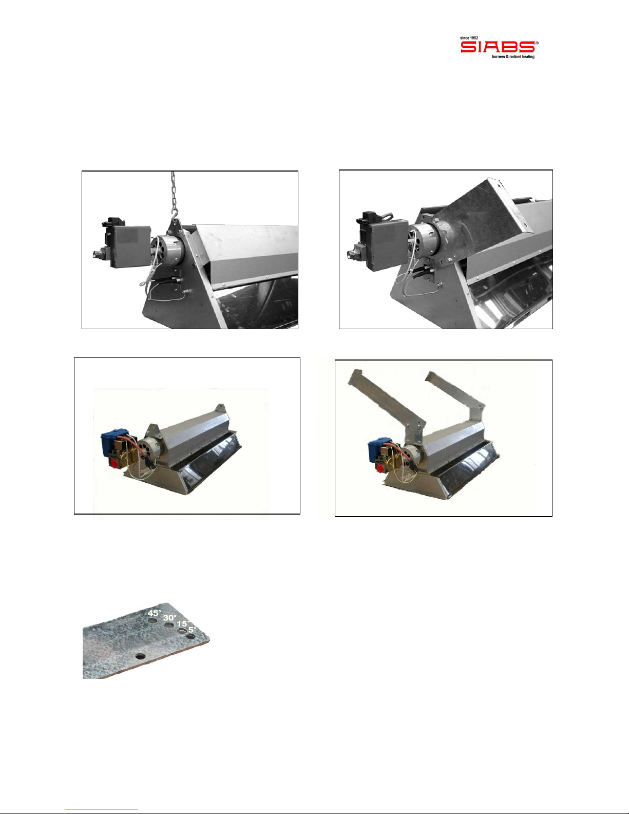
Positioning
The appliances can be installed on walls / pillars, or hanging at ceiling. On request, we can
provide supports (S hooks and chains are excluded) for suspension at ceiling (picture 1), or
wall brackets to fix the heaters on the wall (picture 2) with different angled positions for
the heater. The following figures will show you how to install all types of appliances.
picture 1 – Installation with chains DC picture 2 – Installation at wall DC
picture 1 – Installation with chains DCeco picture 2 – Installation at wall DCeco
The brackets provided by SIABS allow an angle of installation variable once mounted on a wall
or pillar, in order to get a better heat distribution (picture 3, supports for DCeco version)
picture 3 –
different angles : 5° , 15° , 30° , 45°
Manu_ENG_DC_DCeco_rev. 0_04_2012 page 9
IMPORTANT!
at each side of the burner 2 hooks are provided with M8 inserts, for fixing to a wall or
at ceiling by means of appropriate brackets (not supplied, available on request); do not
create other anchor points on the carpentry of the heater and in particular on
the body burner, but use only those designed by the factory
we recommend SIABS original brackets for installation of the radiant heaters
for fixing brackets on a wall or pillars assess the consistency of walls and the load
applied, in order to choose the correct anchors to be used; in any case provide
blocks with M8 screw minimum diameter (e.g. anchor Fischer TA - M in steel, with M8
screw)
IMPORTANT: appliances must be installed in horizontal position, contact us in case of
different inclination. In any case, the system of fixing / suspension must allow thermal
expansion of appliance (some millimetres depending on the model).
Handling
During extraction of the appliances from package and for all operations of handling till final
place of installation, gas valves / flame controls or flanges of the injection group must NOT be
used as lifting points, as in the pictures below.
Appliances must be taken at the installation point / height inside its package or using M8
inserts: all other parts of the appliances are NOT designed to withstand its weight.
NO !! NO !!
Manu_ENG_DC_DCeco_rev. 0_04_2012 page 10
MINIMUM height of installation (for people comfort)
Indicative heights for the installation of appliances are as follows:
MODEL HEIGHT of INSTALLATION (mt)
4P 3,0
6P 3,5
8P 4,0
10P 5,0
12PR 5,5
12P 6,0
16P 7,0
10+10P 8,0
12+12P 9,0
16+16P 10,0
Height “MIN" means the minimum height at which the appliance should be installed so that
people who are in radiated zone, are not subject to excessive heat.
Quotes relate to appliances installed in horizontal position; for appliances with angled
position (15 ÷ 60 °), the minimum height can be reduced roughly between a 5 % (15 ° angle)
and a 20 % (60 ° angle).
Quotes relate to installation with ambient temperature of 10 ÷ 12 °C; in case of ambient
with higher or lower temperatures the minimum height of installation must be reviewed;
consider a reduction of 5 % (for temperatures lower of approx. 5 ° C) or increase of 5 % (for
temperatures higher of approx. 5 ° C).
Above MINIMUM heights of installation are indicative, consult us each case to select the
most advisable unit and the best height of installation (mostly for limit values), and for doubts
about MAXIMUM height of installation.

Manu_ENG_DC_DCeco_rev. 0_04_2012 page 11
MINIMUM distances from flammable surfaces
IMPORTANT: flammable materials inside the radiation could begin to burn and cause fires.
Minimum distances of installation must be respected between the heating surface of the
appliances and the adjacent walls, inside the area of radiation and outside, if they are
not protected against radiation or are flammable materials; in case below minimum
distances can not be met, consider to mount screens for the heat.
Pay special attention also in cases of installing appliances above crane ways, to prevent
damage to motor and electric cables!
The MINIMUM distances are as follows:
MODEL MINIMUM distance (mt) between heater and ...
ceiling floor front sides
4P 1,0 2,0 1,0 1,0
6P 1,0 2,5 1,0 1,0
8P 1,5 3,0 1,5 1,5
10P 1,5 4,0 1,5 1,5
12PR 1,5 4,5 2,0 1,5
12P 1,5 4,5 2,0 1,5
16P 1,5 5,0 2,0 1,5
10+10P 2,0 5,5 2,5 2,0
12+12P 2,0 6,0 2,5 2,0
16+16P 2,0 6,5 2,5 2,0
NOTE – contact us in case of different distances or special cases
SURFACES CLOSE to APPLIANCES MUST BE DONE IN MATERIAL of
CLASS 'A0' with respect TO FIRE RESPONSE (NOT COMBUSTIBLE and
NOT FLAMMABLE) and with DEGREE of RESISTANCE TO FIRE EQUAL
or MORE THAN "REI 90"

Manu_ENG_DC_DCeco_rev. 0_04_2012 page 12
Connection to GAS supply
IMPORTANT: hydraulic connection of the appliances to the gas distribution net must be made
according to information given in this technical book exclusively by professionally qualified
staff.
The appliances are supplied according to the type of gas chosen, and then before making the
connection to the power network of gas, make sure that the gas used and pressure of gas
circuit correspond to what is shown on the data plate label of the unit. Before
connection to the gas pipeline, make sure that the pipes are properly cleaned and
produced in accordance with regulations in force in the country of installation.
NOTICE: provide a fuel interception tap close to the appliance, and with easily accessible
position; make the connection between the appliance and the gas network using an
approved steel flexible pipe.
IMPORTANT: "GAS supply pressure", defined as the dynamic pressure of the circuit,
or part of the circuit downstream of the pressure reducer, with all the appliances running,
and must be detected in this condition. With lower pressure difficulties in start-up may
occur.
Once the connection is made, in compliance with the rules in force in the country of
installation, a) verify the sealing of hydraulic pipes and gas connection to the unit, b) check
that the pressure is correct, c) make sure that the apparatus functions in the conditions for
which it was prepared.
Gas connection is 1/2" for appliances with 1 burner (models: 4P, 6P, 8P, 10P, 12PR, 12P e
16P); 3/4” for appliances with 2 burners and 2 gas groups (models: 10+10P, 12+12P,
16+16P); 1/2” for appliances with 2 burners and 1 gas group (models: 10+10PS, 12+12PS
and 16+16PS).
Appliances are equipped with a multifunctional group comprising: double seat valve fitted with
pressure stabilizer and integrated flame control. The stabilizer accepts a maximum inlet
pressure of 50 mbar and the valve is equipped with a pressure intakes, to measure and
control incoming and outgoing pressures.
IMPORTANT: all appliances are supplied already tested and set to the properly operating
pressure; DO NOT remove seal on the pressure regulator (R): expiring of guarantee!
Feeding gas pipeline must be kept at a distance of at least 1 m from the zone
of discharge of the combustion products and must not be exposed to direct
irradiation of appliances
Manu_ENG_DC_DCeco_rev. 0_04_2012 page 13
Connection to ELECTRIC feeding
IMPORTANT: the electrical connection of the equipment shall be made in accordance
with the directions given in this technical book exclusively by professionally qualified
personnel. The installation must be carried out in accordance with regulations in the
country of installation.
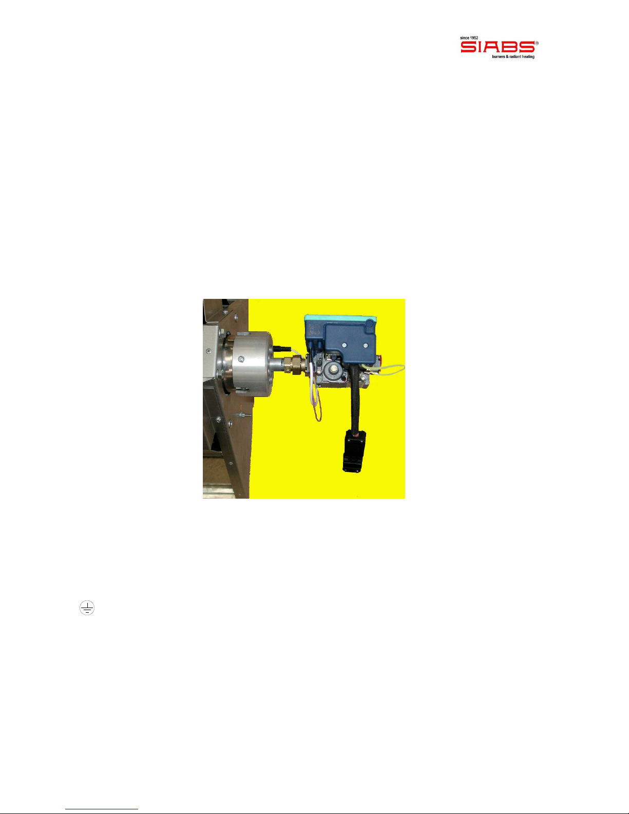
The appliance must be fed with 230 Volt / Single Phase / 50 Hz feeding. The control flame
mounted on gas valve has a plug/socket connection with security hook (picture 3). Mount a
bipolar switch upstream of the heater for switch-on and switch-off, so you can isolate it from
electric supply. Use this manual for the size of the power supply line, or refer to the data given
in the plate label of the heater. In any case, use a cable with minimum section 3x1.5mm2(ON-
OFF version) or 4x1.5mm2(TWO-STAGE version).
The wiring diagrams are shown on page 14 (ON-OFF version) and page 17 (TWO-STAGE
version) of this manual.
Picture 3 – Connector for electric connection
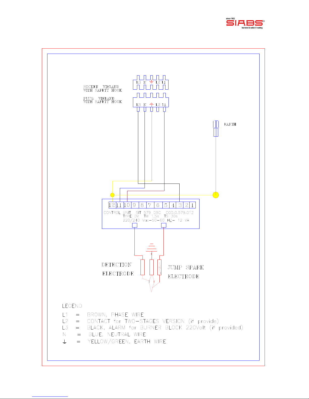
For the electrical connection unlock the plug and unscrew its case; connect a cable according
to the indications given on the terminal plug, namely:
L1 phase wire
Nneutral wire
earth wire
L2 modulator command for two-stages gas valve (if provided)
L3 signal for burner block (if provided)
IMPORTANT: it is essential for the smooth functioning of the appliances, to respect the
Phase / Neutral polarity, with that indicated on the power connector.
IMPORTANT: it is also essential for the smooth functioning of the appliances, and for the
safety of the user, efficient plant grounding, executed according to existing regulations.
Under no circumstances you can use the gas connection pipeline as grounding of equipment.
Manu_ENG_DC_DCeco_rev. 0_04_2012 page 14
WIRING DIAGRAM, “SIT” control unit ON-OFF

Manu_ENG_DC_DCeco_rev. 0_04_2012 page 15
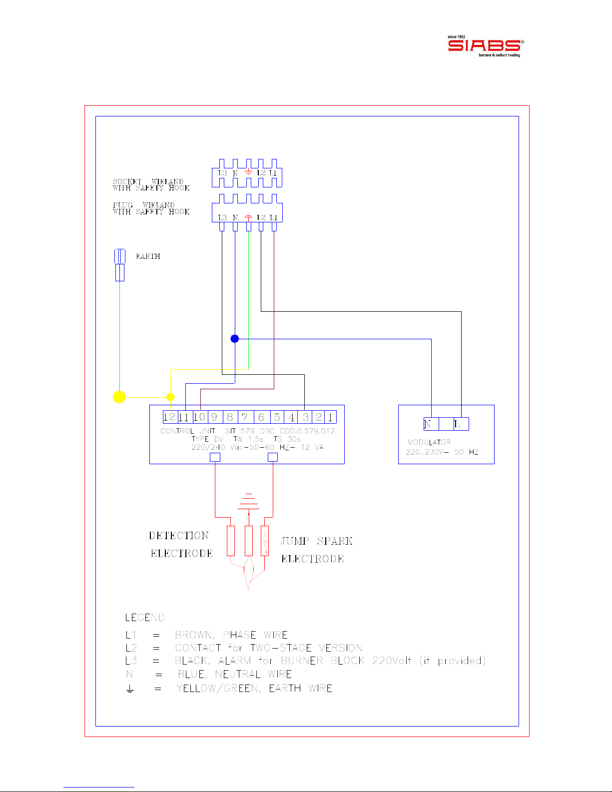
NOTE for “SIT” TWO-STAGE gas valve
IMPORTANT:
- for this version, a specific switch for pressure modulator feeding must be placed in the
main electric switchboard
modulator fed: HIGH pressure running
modulator NOT fed: LOW pressure running
- start-up of the appliance must always take place with the modulator fed (HIGH
pressure running)
- you will find the data (heat input, pressure and gas flow rate) referring to the
appliances with TWO-STAGE version, in the tables at page 6 of this manual.
N.B. – MINIMUM heating capacity = feed L1 + N
– MAXIMUM heating capacity = feed L1 + L2 + N
You will find the data (heat input, pressure and gas flow rate) referring to the appliances with
TWO-STAGE version, in the tables at page 6 of this manual.
The TWO-STAGE version allows:
save on gas consumption
better comfort condition for people
lower number of start-up / switch-off of the heater
power reserve for particularly cold winters

Manu_ENG_DC_DCeco_rev. 0_04_2012 page 16
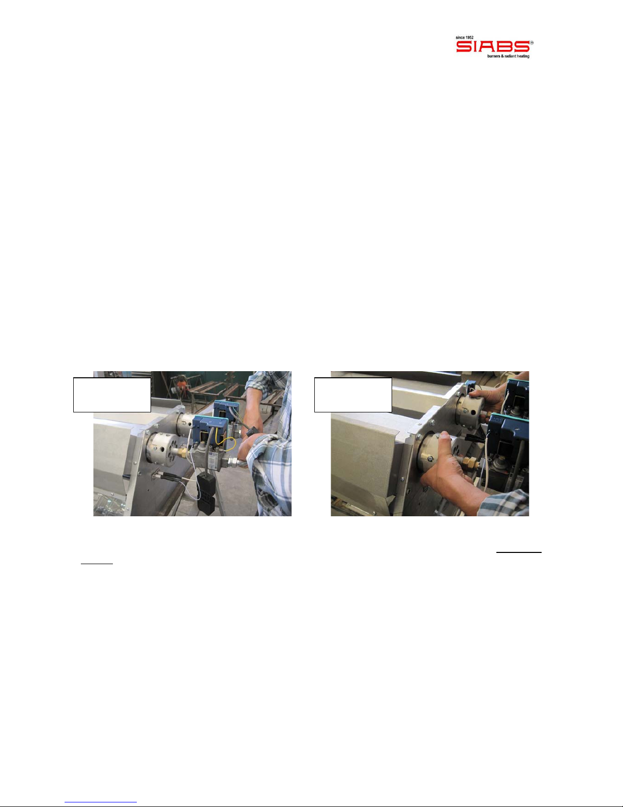
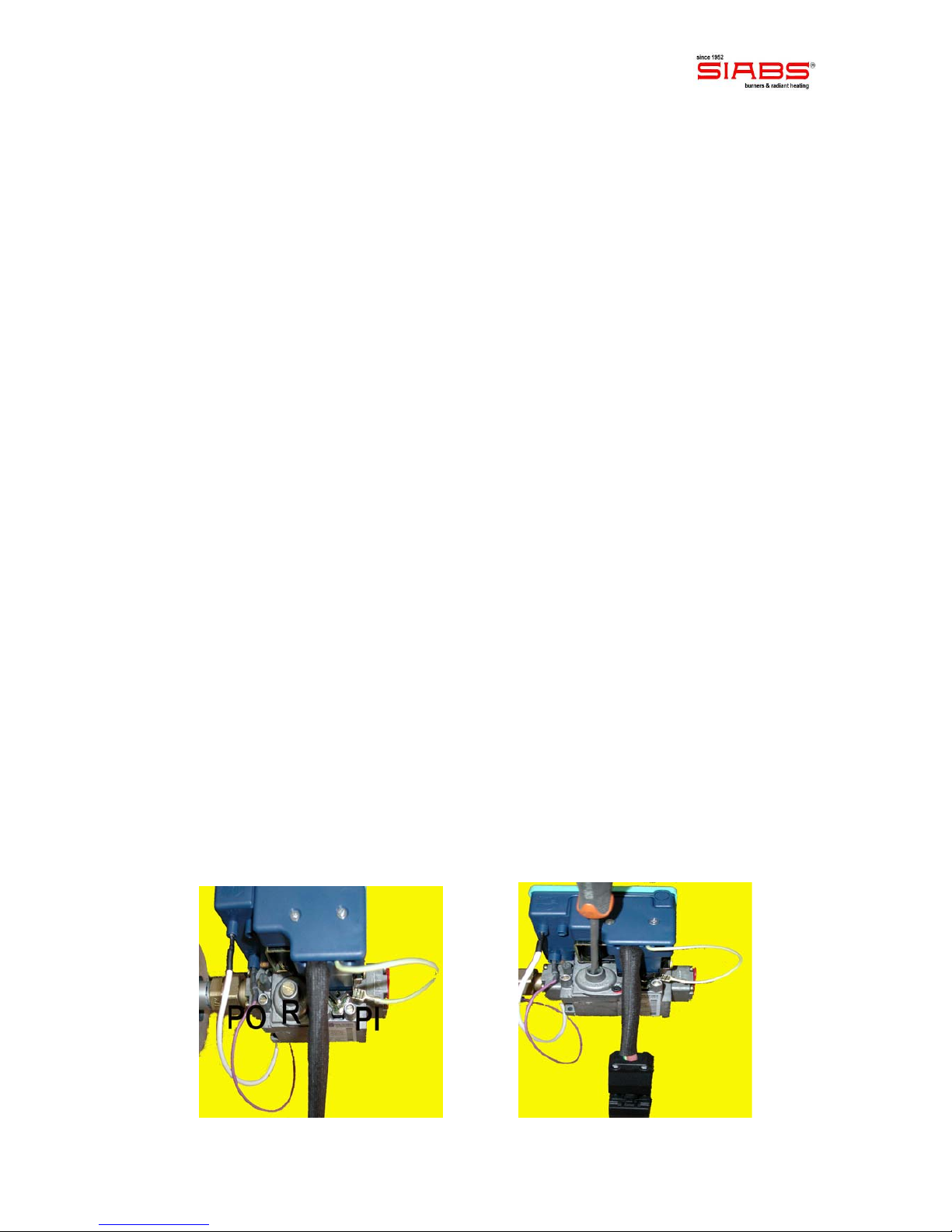
Setting of the pressure
Unscrew the screw of the PO pressure intake of the gas valve before the nozzle (pictures 1.A
and 1.B), and connect a water column manometer. Feed the modulator and take out the
yellow tap of the pressure regulator. Act, as shown in picture 2, on the CH10 screw for setting
of the maximum pressure, till you get the required pressure (turn clockwise to increase
and counter clockwise to decrease). Take out tension at the pressure modulator, and with
a screw-driver act on the inner screw for minimum setting (picture 3) till you get the required
pressure (turn clockwise to increase and counter clockwise to decrease).
Picture 1.A Picture 1.B
Picture 2 Picture 3
Manu_ENG_DC_DCeco_rev. 0_04_2012 page 17
WIRING DIAGRAM, “SIT” control unit TWO-STAGE
Manu_ENG_DC_DCeco_rev. 0_04_2012 page 18
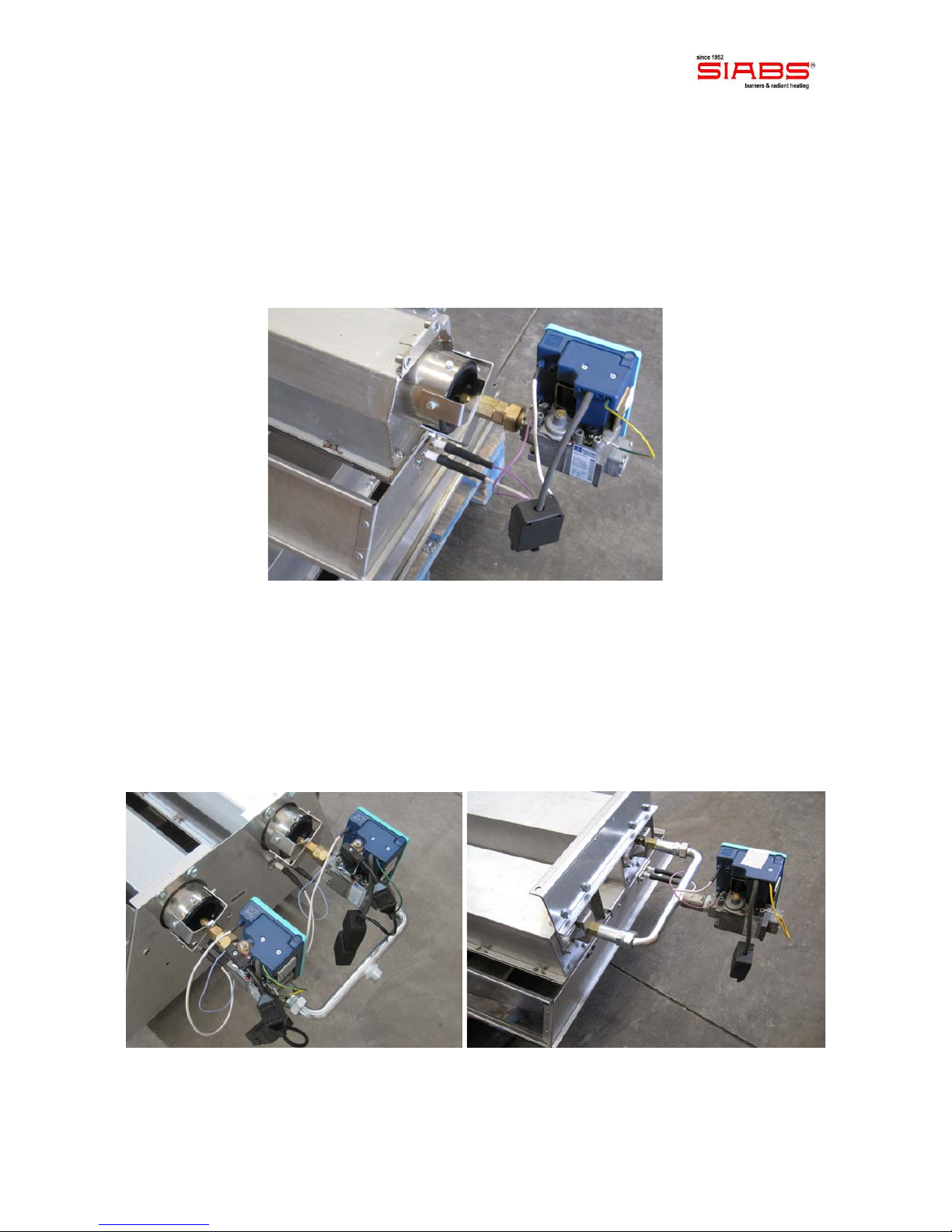
Gas group (gas valve and flame control)
You can find 3 different cases (both ON-OFF and TWO-STAGES versions):
A_appliances with 1 burner, models 4P, 6P, 8P, 10P, 12P e 16P
They are equipped with 1 gas valve and 1 flame control
B_appliances with 2 burners, models 10+10P, 12+12P e 16+16P
Appliances with 2 burners can be equipped with:
- 2 gas valves and 2 flame controls models: 10+10P, 12+12P e 16+16P (Picture A)
or
- 1 gas valve and 1 flame control, models: 10+10PS, 12+12PS e 16+16PS (Picture B)
Picture A Picture B
Manu_ENG_DC_DCeco_rev. 0_04_2012 page 19
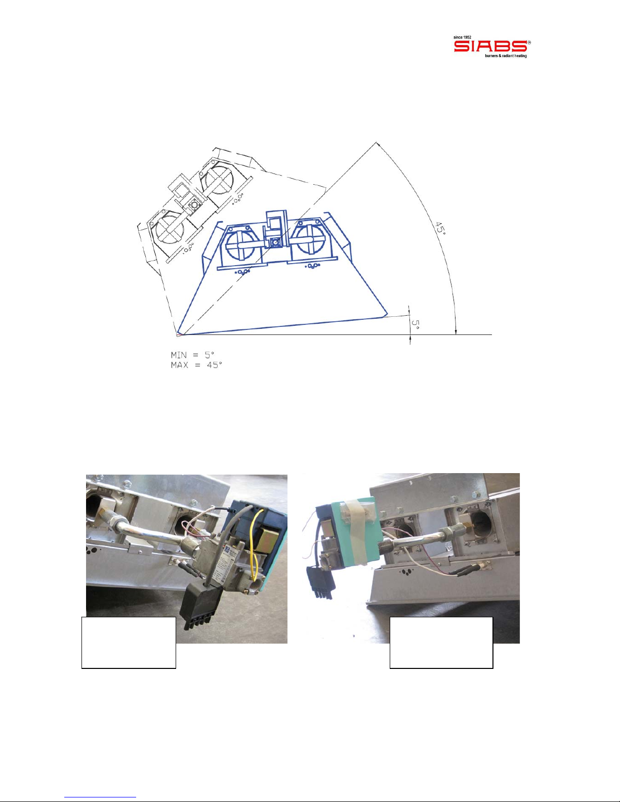
IMPORTANT: appliances with 2 burners and only 1 gas group (gas valve and flame control)
can be installed with MINIMUM inclination = 5 % and MAXIMUM inclination = 45 %;
outside this range the start-up between the 2 burners and safety of the units is NOT
guaranteed.
IMPORTANT: appliances with 2 burners and only 1 gas group (gas valve and flame control)
are equipped with only 1 electrodes set (detection and spark) for command and running of the
whole unit, so both the burners; the burner with the electrodes group MUST STAY in the
lower part of the unit when installed.
YES
NO !
Manu_ENG_DC_DCeco_rev. 0_04_2012 page 20
PUT IN OPERATION and FIRST START-UP
When you first start the appliances is important to make some preliminary checks to
ensure its proper running; operations listed below are considered essential:
make sure there are no losses in the gas line and that is properly sized
check that the pressure and type of gas used comply with the data on the plate
of the characteristics of the appliance
check that the power electric line has been correctly sized, which has been respected
phase - neutral polarity and that the cable grounding is connected
make sure the mechanical installation (supports) of the appliance have been properly
carried out and that the connections bolts are tight
use only steel materials, since heat is transferred from appliances to supports
Start-up sequence includes the following phases:
giving tension to the appliances, ignition electrode begins sparkling, and the gas valve
opens
the sparkling electrode ends after 30 seconds
in the case has not been detected the presence of flame, control flame goes into block
after 30 seconds; for re-start it is necessary to remove tension for a period of not less
than 20 seconds: after that period of time, the start-up sequence can be repeated; if
the heater continues going into block, refer to the section 'Maintenance' of this manual
switch-off of the heater is done by taking out power supply to control unit
IMPORTANT: in case of failure at time of first start-up, pressure settings have to be
checked, acting on PO and PI pressure intakes
Only in case of maintenance, following instruction of qualified SIABS personnel,
pressure settings can be modified using the following procedure:
remove the cap of pressure regulator (R)
unscrew the screw of intake pressure, upstream at the nozzle (PO) and connect a
suitable gauge, to check correct pressure during setting
remove the cap of pressure regulator (R) and act, as shown in pictures (turn
clockwise to increase and counter clockwise to decrease), on the screw of
adjustment till match up to the pressure gauge reading with that stated on plate on
the characteristics
the new and correct nozzle pressure should be checked at intake pressure PO
disconnect the pressure gauge and close the screw of intake pressure (PO)
reassemble the cap of the regulator R and place a new suitable seal
This manual suits for next models
27
Table of contents
Other Siabs Heater manuals

Popular Heater manuals by other brands


Clatronic
Clatronic HL 3763 instruction manual

Flagro
Flagro FVO-400 Operating instructions manual

DeLonghi
DeLonghi HCM2030 Instructions for use

Frost Fighter
Frost Fighter IDH400QR LP/NG Installation - Operation/Maintenance Instructions and Parts List

Fagor
Fagor TRV-240 Instructions for use

Saunum
Saunum Air-5 Instructions for use

DeLonghi
DeLonghi HS instructions

IXL
IXL fresco Aurora Quick setup guide

Clarke
Clarke DEVIL 370SPC Operating & maintenance instructions

Archgard
Archgard EURO 35 Users installation operation & maintenance manual

IRSAP
IRSAP THE RADIATOR COMPANY ISEO TRC-IS-O30 Fitting instructions

Sennheiser
Sennheiser SI 1015 quick guide