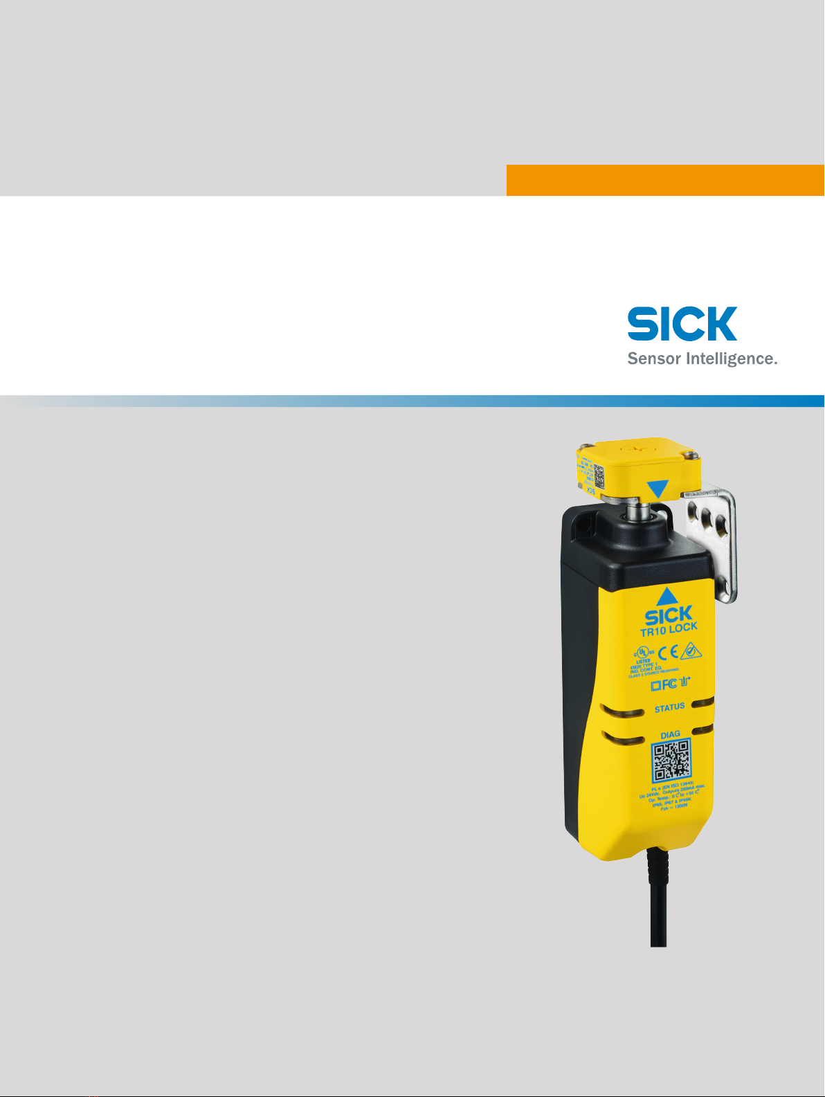
SICK TR10 Lock User manual
OPERATING INSTRUCTIONS
TR10 Lock
Safety locking device

Described product
TR10 Lock
Manufacturer
SICK AG
Erwin-Sick-Str. 1
79183 Waldkirch
Germany
Legal information
This work is protected by copyright. Any rights derived from the copyright shall be
reserved for SICK AG. Reproduction of this document or parts of this document is only
permissible within the limits of the legal determination of Copyright Law. Any modifica‐
tion, abridgment or translation of this document is prohibited without the express writ‐
ten permission of SICK AG.
The trademarks stated in this document are the property of their respective owner.
© SICK AG. All rights reserved.
Original document
This document is an original document of SICK AG.
2O P E R A T I N G I N S T R U C T I O N S | TR10 Lock 8019972/2016-07-19 | SICK
Subject to change without notice

Contents
1 About this document........................................................................ 5
1.1 Function of this document....................................................................... 5
1.2 Scope......................................................................................................... 5
1.3 Additional information.............................................................................. 5
1.4 Symbols and document conventions...................................................... 5
2 Safety information............................................................................ 7
2.1 General safety notes................................................................................. 7
2.2 Intended use............................................................................................. 7
2.3 Requirements for the qualification of personnel.................................... 7
3 Product description........................................................................... 8
3.1 Setup and function................................................................................... 8
3.2 Product characteristics............................................................................. 8
3.3 Manual deactivation................................................................................. 9
4 Project planning................................................................................ 11
4.1 Manufacturer of the machine.................................................................. 11
4.2 Operator of the machine.......................................................................... 11
4.3 Assembly................................................................................................... 12
4.4 Integrating into the electrical control...................................................... 13
4.5 Testing plan............................................................................................... 16
5 Mounting............................................................................................. 17
5.1 Safety......................................................................................................... 17
5.2 Installation................................................................................................ 17
6 Electrical installation........................................................................ 21
6.1 Safety......................................................................................................... 21
6.2 Notes on cULus......................................................................................... 21
6.3 Device connection (M12, 8-pin).............................................................. 21
6.4 Device connection (flying lead)................................................................ 22
6.5 Connecting a cascade.............................................................................. 22
7 Commissioning.................................................................................. 25
7.1 Switching on.............................................................................................. 25
7.2 Teach-in..................................................................................................... 25
7.3 Testing....................................................................................................... 26
8 Troubleshooting................................................................................. 27
8.1 Safety......................................................................................................... 27
8.2 Diagnostic LEDs........................................................................................ 27
9 Technical data.................................................................................... 30
9.1 Technical data........................................................................................... 30
CONTENTS
8019972/2016-07-19 | SICK O P E R A T I N G I N S T R U C T I O N S | TR10 Lock 3
Subject to change without notice

9.2 Response time.......................................................................................... 32
9.3 Course of the output signal switching device test over time................. 32
9.4 Dimensional drawings.............................................................................. 33
10 Ordering information........................................................................ 35
10.1 Scope of delivery...................................................................................... 35
10.2 Ordering information for TR10 Lock........................................................ 35
11 Accessories........................................................................................ 36
11.1 Actuator..................................................................................................... 36
11.2 Connectivity............................................................................................... 36
11.3 Mounting bracket...................................................................................... 38
11.4 Mounting accessories.............................................................................. 38
12 Annex.................................................................................................. 39
12.1 Compliance with EU directives................................................................. 39
12.2 FCC and IC radio approval........................................................................ 40
CONTENTS
4O P E R A T I N G I N S T R U C T I O N S | TR10 Lock 8019972/2016-07-19 | SICK
Subject to change without notice
1 About this document
1.1 Function of this document
These operating instructions contain the information needed during the life cycle of the
safety locking device.
These operating instructions must be made available to all people who work with the
safety locking device.
1.2 Scope
These operating instructions only apply to the TR10 Lock safety locking device.
1.3 Additional information
www.sick.com
The following information is available on the Internet:
•versions in other languages
•data sheets and application examples
•CAD data of drawings and dimensional drawings
•certificates (e.g. EU declaration of conformity)
•Guide for Safe Machinery (Six steps to a safe machine)
1.4 Symbols and document conventions
The following symbols and conventions are used in this document:
Safety notes and other notes
DANGER
Indicates a situation presenting imminent danger, which will lead to death or serious
injuries if not prevented.
WARNING
Indicates a situation presenting possible danger, which may lead to death or serious
injuries if not prevented.
CAUTION
Indicates a situation presenting possible danger, which may lead to moderate or minor
injuries if not prevented.
NOTICE
Indicates a situation presenting possible danger, which may lead to property damage if
not prevented.
NOTE
Indicates useful tips and recommendations.
Instructions to action
bThe arrow denotes instructions to action.
ABOUT THIS DOCUMENT 1
8019972/2016-07-19 | SICK O P E R A T I N G I N S T R U C T I O N S | TR10 Lock 5
Subject to change without notice

1. The sequence of instructions for action is numbered.
2. Follow the order in which the numbered instructions are given.
✓The check mark denotes the result of an instruction.
LED symbols
These symbols indicate the status of an LED:
The LED is off.
The LED is flashing.
The LED is illuminated continuously.
Terminology
Dangerous state
A dangerous state is a status of the machine or facility, where people may be injured.
Protective devices prevent this risk if the machine is operated within its intended use.
The figures in this document always show the dangerous state of the machine as move‐
ment of a machine part. In practice, there are different dangerous states, such as:
•Machine movements
•Electrical parts
•Visible and invisible beam
•A combination of multiple hazards
1 ABOUT THIS DOCUMENT
6O P E R A T I N G I N S T R U C T I O N S | TR10 Lock 8019972/2016-07-19 | SICK
Subject to change without notice

2 Safety information
2.1 General safety notes
The safety locking device must be configured and operated correctly by qualified safety
personnel according to the machine requirements.
2.2 Intended use
When used in conjunction with a movable physical guard and the machine controller,
the safety locking device prevents the protective device from being opened while a dan‐
gerous machine function is being executed.
The safety locking device may only be used on the machine on which it was configured,
mounted, installed, and commissioned by qualified safety personnel in accordance with
these operating instructions.
Incorrect use, improper modification of or tampering with the safety locking device will
invalidate any warranty from SICK AG; in addition, any responsibility and liability of SICK
AG for damage and secondary damage caused by this is excluded.
NOTE
The safety locking device is also suitable for process protection.
2.3 Requirements for the qualification of personnel
The safety locking device must be configured, installed, connected, commissioned, and
serviced only by qualified safety personnel.
Project planning
For project planning, a person is considered competent when he/she has expertise and
experience in the selection and use of protective devices on machines and is familiar
with the relevant technical rules and national work safety regulations.
Mechanical mounting, electrical installation, and commissioning
For the task, a person is considered qualified when he/she has the expertise and expe‐
rience in the relevant field and is sufficiently familiar with the application of the protec‐
tive device on the machine to be able to assess whether it is in an operationally safe
state.
Operation and maintenance
For operation and maintenance, a person is considered competent when he/she has
the expertise and experience in the relevant field and is sufficiently familiar with the
application of the protective device on the machine and has been instructed by the
machine operator in its operation.
SAFETY INFORMATION 2
8019972/2016-07-19 | SICK O P E R A T I N G I N S T R U C T I O N S | TR10 Lock 7
Subject to change without notice

3 Product description
3.1 Setup and function
The safety locking device is an interlocking device with a lock consisting of a non-con‐
tact safety switch and a coded actuator. Depending on the product variant, the actuator
either has a low (universally coded) or high (unique coded) coding level.
When the protective device is closed, the actuator is guided to the safety switch. When
the actuation field is reached, the actuator code is read and analyzed via RFID. If the
code is valid, the application diagnostic output switches. When the locking command is
active, the guard locking pin is extended. If the guard locking pin is detected in the
actuator, the locking process has been successful and the safe output signal switching
devices (OSSD) are switched.
The safety locking device can only be locked when the protective device is closed.
The guard locking pin is actuated by a bistable solenoid. This means that the safety
locking device consumes little electricity and does not produce any heat. Nevertheless,
the function of a safety locking device is executed via the electronics according to the
“power to release” or “power to lock” principle.
3.2 Product characteristics
3.2.1 Product variants
The safety locking device is delivered in different variants. An overview of important dis‐
tinguishing features between the variants is provided below.
•Designed according to “power to release” or “power to lock” principle
•Versions for universally coded or unique coded actuators
•Cable with M12 plug connector (0.2 m) or flying leads (3 or 10 m)
Complete overview of all variants: see "Ordering information for TR10 Lock", page 35
Variant according to “power to release” principle
•Activate lock: no voltage at lock input
•Deactivate lock: voltage at lock input
When the voltage at the lock input is interrupted, the lock remains activated and the
protective device cannot be opened immediately.
Variant according to “power to lock” principle
•Activate lock: voltage at lock input
•Deactivate lock: no voltage at lock input
When the voltage is interrupted, the lock is deactivated and the protective device can
be opened immediately.
DANGER
Hazard due to lack of effectiveness of the protective device
If the voltage drops, the safety locking device deactivates regardless of whether the
dangerous state of the machine has ended
bAssess the accident risk. The device must be configured correctly in order to be
used for protection of personnel.
Variant for universally coded actuators
All universally coded actuators are accepted. No teach-in is required.
3 PRODUCT DESCRIPTION
8O P E R A T I N G I N S T R U C T I O N S | TR10 Lock 8019972/2016-07-19 | SICK
Subject to change without notice

Variant for unique coded actuators
A unique coded actuator must be taught in during commissioning. Up to 8 actuators
can be taught in one after another. Only the most recently taught-in actuator is valid.
When teaching in an actuator, the safety locking device can be permanently coded
(optional). If the safety locking device is permanently coded, no further actuators can
be taught in. This cannot be undone.
3.2.2 OSSD
Output signal switching device: signal output for the protective device, which is used for
stopping the dangerous movement.
An OSSD is a safety switching output. The functionality of each OSSD is tested periodi‐
cally. OSSDs are always connected in pairs and must undergo dual-channel analysis for
safety reasons. An OSSD pair is formed from two OSSDs that are connected and ana‐
lyzed together.
3.3 Manual deactivation
In some situations, it may be necessary to deactivate the lock manually (e.g., in the
event of faults). A functional test must be carried out after the lock has been deacti‐
vated.
Mechanical unlocking mechanism
In the event of functional faults, the safety locking device can be deactivated with the
mechanical unlocking mechanism regardless of the state of the electromagnet. The
mechanical unlocking mechanism is not suitable for emergency release or escape
release.
When the mechanical unlocking mechanism is actuated, the lock is deactivated and
the OSSDs switch off. This must generate a stop command.
Actuating the mechanical unlocking mechanism
bGuide a screwdriver with a max. diameter of 2.5 mm through the actuator and
push the guard locking pin into the safety locking device.
✓The lock is deactivated. The safety locking device switches to the fault state (DIAG
light emitting diodes flash red).
After using the mechanical unlocking mechanism, disconnect the voltage supply from
the safety locking device and then reconnect. The safety locking device restarts.
PRODUCT DESCRIPTION 3
8019972/2016-07-19 | SICK O P E R A T I N G I N S T R U C T I O N S | TR10 Lock 9
Subject to change without notice

< 2,5
Figure 1: Mechanical unlocking mechanism
3 PRODUCT DESCRIPTION
10 O P E R A T I N G I N S T R U C T I O N S | TR10 Lock 8019972/2016-07-19 | SICK
Subject to change without notice

4 Project planning
4.1 Manufacturer of the machine
DANGER
Failure to comply with manufacturer’s obligations
Hazard due to lack of effectiveness of the protective device
bCarry out a risk assessment before using the safety locking device.
bDo not tamper with, open, or modify the components of the safety locking device.
bMake sure that the safety locking device is only repaired by the manufacturer or by
someone authorized by the manufacturer. Improper repair can lead to a loss of the
protective function.
bMake sure that switch-on commands which bring about a dangerous state of the
machine are not enabled until the protective device is closed and the lock is acti‐
vated.
bMake sure that the lock is not deactivated until the dangerous state of the
machine has stopped.
bMake sure that closing a protective device and activating the lock does not cause
a dangerous machine function to start by itself. This must be controlled by a sepa‐
rate start command.
bThe safety locking device must not be bypassed (contacts jumpered), turned away,
removed, or rendered ineffective in any other way. Take measures to reduce
bypassing options as necessary.
The safety locking device is designed in such a way as to eliminate internal faults
according to ISO 13849–2, Table A4.
Observe EN ISO 14119 on the use of interlocking devices in conjunction with physical
guards.
4.2 Operator of the machine
DANGER
Failure to observe operator obligations
Hazard due to lack of effectiveness of the protective device
bChanges to the machine and changes to the mechanical mounting of the safety
locking device necessitate a new risk assessment. The results of this risk assess‐
ment may require the operator of the machine to meet a manufacturer’s obliga‐
tions.
bApart from the procedures described in this document, the components of the
safety locking device must not be opened or modified.
bDo not carry out any repair work on components. Improper repair of the safety
locking device can lead to a loss of the protective function.
bMake sure that replacement actuators are not used for bypassing. Restrict access
to actuators.
PROJECT PLANNING 4
8019972/2016-07-19 | SICK O P E R A T I N G I N S T R U C T I O N S | TR10 Lock 11
Subject to change without notice

4.3 Assembly
DANGER
Bypassing the protective device
Hazard due to lack of effectiveness of the protective device
bPrevent any incentives to tamper with the safety locking device; for example, with
the following measures:
Variant for universally coded actuators only:
°Cover the safety switch and the actuator with additional equipment or protect
them against access.
Actuation direction
The safety locking device can be actuated from all 4 horizontal directions. The lock only
locks in the actuation direction, i.e., to the side.
421 3
Figure 2: Possible actuation directions
From front
From left
From rear
From right
The safety locking device is not suitable for vertical actuation. The lock does not pre‐
vent the actuator being moved upward out of the response range.
Figure 3: No vertical lock
Distance
If multiple safety locking devices are mounted on the machine, they must be mounted
at least 120 mm apart.
4 PROJECT PLANNING
12 O P E R A T I N G I N S T R U C T I O N S | TR10 Lock 8019972/2016-07-19 | SICK
Subject to change without notice

120
120
Figure 4: Min. distance for multiple safety switches
Alignment
The safety locking device can be mounted in any alignment.
Figure 5: Possible alignment of the safety locking device
4.4 Integrating into the electrical control
Switch-on commands which bring about a dangerous state of the machine must not be
enabled until the protective device is closed and the lock is activated. The lock must
not be deactivated until the dangerous state has ended. Depending on the safety con‐
cept, the signal is analyzed by, e.g., safety relays or a safety controller.
4.4.1 Lock
The logic to generate a locking command with the control changes depending on the
product variant selected.
Variant according to “power to release” principle
To lock, make sure there is no voltage at the “lock input” contact (locking command
active).
To unlock, apply 24 V DC voltage at the “lock input” contact (locking command inac‐
tive).
For variants according to “power to lock” principle
PROJECT PLANNING 4
8019972/2016-07-19 | SICK O P E R A T I N G I N S T R U C T I O N S | TR10 Lock 13
Subject to change without notice
To lock, apply 24 V DC voltage at the “lock input” contact (locking command active).
To unlock, make sure there is no voltage at the “lock input” contact (locking command
inactive).
4.4.2 OSSDs
Safety locking devices with local inputs and outputs can be directly integrated into the
machine controller.
DANGER
Hazard due to lack of effectiveness of the protective device
In the case of non-compliance, it is possible that the dangerous state of the machine
may not be stopped or not stopped in a timely manner.
bMake sure that the following control and electrical requirements are met so the
protective function can be fulfilled.
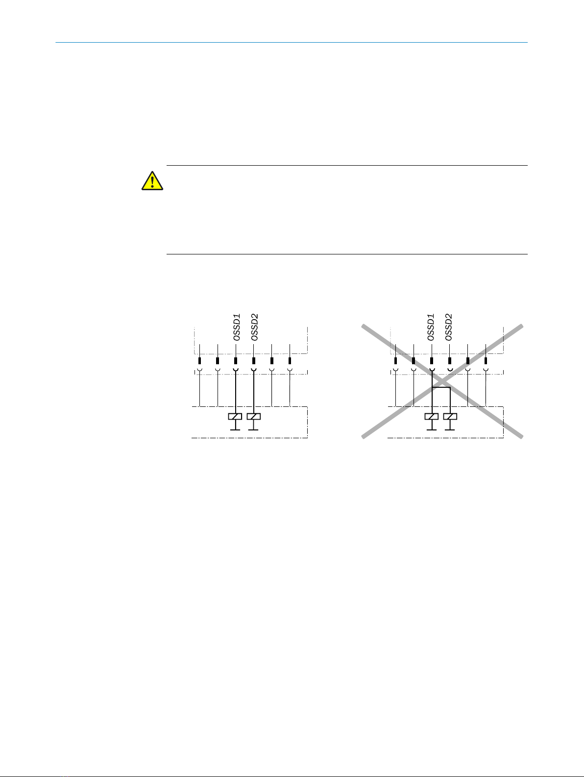
•The output signals from an OSSD pair must not be connected to each other.
•In the machine controller, both signals from an OSSD pair must be processed sep‐
arately.
Figure 6: Dual-channel and isolated connection of OSSD 1 and OSSD 2
•The machine must switch to the safe state at any time if at least one OSSD in an
OSSD pair switches to the OFF state.
4 PROJECT PLANNING
14 O P E R A T I N G I N S T R U C T I O N S | TR10 Lock 8019972/2016-07-19 | SICK
Subject to change without notice
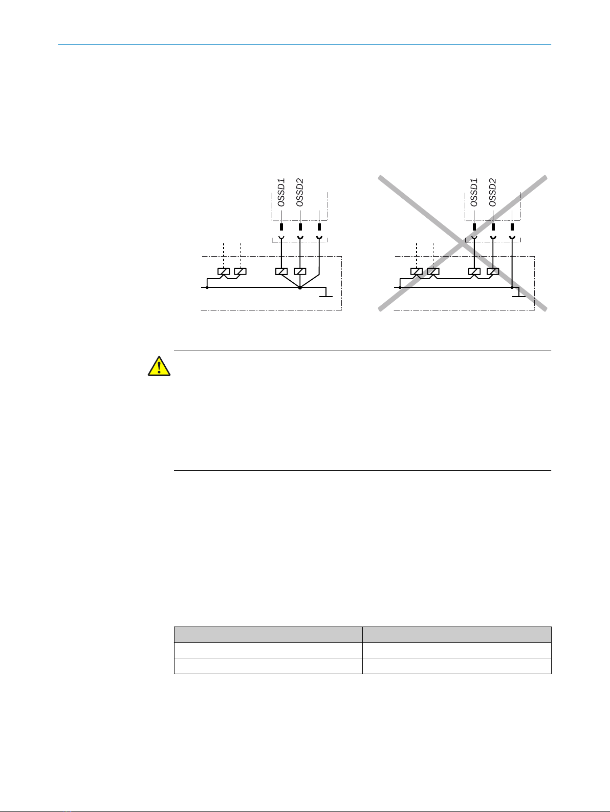
•Prevent the formation of a potential difference between the load and the protec‐
tive device. If you connect loads to the OSSDs (safety outputs) that also switch if
controlled with negative voltage (e.g., electro-mechanical contactor without
reverse polarity protection diode), you must connect the 0 V connections of these
loads and those of the corresponding protective device individually and directly to
the same 0 V terminal strip. In the event of a fault, this is the only way to ensure
that there can be no potential difference between the 0 V connections of the loads
and those of the corresponding protective device.
Figure 7: No potential difference between load and protective device
DANGER
Hazard due to lack of effectiveness of the protective device
In the case of non-compliance, it is possible that the dangerous state of the machine
may not be stopped or not stopped in a timely manner.
Downstream contactors must be positively guided and monitored depending on appli‐
cable national regulations or required reliability of the safety function.
bMake sure that downstream contactors are monitored (external device monitoring,
EDM).
Requirements for the electrical control of the machine
The OSSDs are short-circuit protected to 24 V DC and 0 V. When the safety locking
device is locked, the OSSDs signal the ON state with the HIGH signal level (non-iso‐
lated). If the safety locking device is unlocked or there is a device fault, the OSSDs sig‐
nal the OFF state with the LOW signal level.
4.4.3 Application diagnostic output
The application diagnostic output signal changes as soon as the actuator is moved into
or leaves the response range of the safety switch. In other words, it does so when the
moving protective device is opened and closed. This is not a safety output.
Actuator Application diagnostic output
Actuator not in response range. ON
Actuator in response range. OFF
Table 1: Application diagnostic output switching behavior
4.4.4 Cascading
Cascading can be used to connect multiple safety locking devices. The connected devi‐
ces will provide the combined safety outputs and therefore act outwardly like one
device.
PROJECT PLANNING 4
8019972/2016-07-19 | SICK O P E R A T I N G I N S T R U C T I O N S | TR10 Lock 15
Subject to change without notice
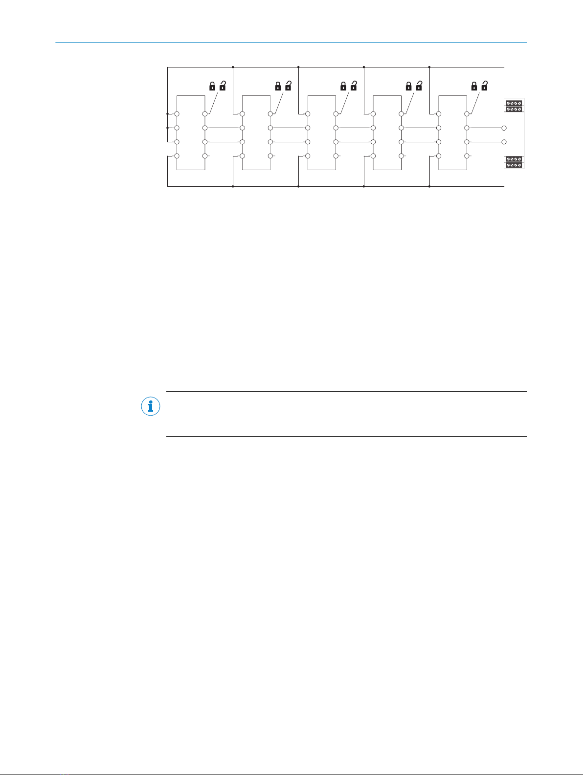
2
8
4
7
3
5
6
1
OSSD1
OSSD2
OSSD1
OSSD2
OSSD1
OSSD2
OSSD1
OSSD2
OSSD1
OSSD2
2
8
4
7
3
5
6
1
2
8
4
7
3
5
6
1
2
8
4
7
3
5
6
1
2
8
4
7
3
5
6
1
24 V DC
0 V DC
1// /// 111 1 2
TR10 Lock
Safe evaluation unit
The maximum number of safety locking devices depends on the following factors:
•Supply voltage applied
•Length of cables used
•Cross-section of cables used
•Load current
The voltage drop in the cascade must be checked to ensure that the defined minimum
voltage is still present at the last safety locking device.
The number of safety locking devices in a cascade affects the response time of the sys‐
tem (see "Response time", page 32).
The cascade can be implemented via special T-connectors and an end connector (see
"Connecting a cascade", page 22).
NOTE
In the case of safety switches cascaded using T-connectors, it is not possible to evalu‐
ate the application diagnostic output.
4.5 Testing plan
The safety locking device must be tested by appropriately qualified safety personnel
when commissioning, after modifications, and at regular intervals.
The regular thorough checks serve to investigate the effectiveness of the safety locking
device and discover defects because of modifications or external influences (such as
damage or tampering).
The manufacturer and user must define the type and frequency of the thorough checks
on the machine on the basis of the application conditions and the risk assessment.
Determination of the thorough checks must be documented in a traceable manner.
4 PROJECT PLANNING
16 O P E R A T I N G I N S T R U C T I O N S | TR10 Lock 8019972/2016-07-19 | SICK
Subject to change without notice

5 Mounting
5.1 Safety
DANGER
Hazard due to unexpected starting of the machine
Death or severe injury
bMake sure that the dangerous state of the machine is and remains switched off.
DANGER
Bypassing the protective device
Hazard due to lack of effectiveness of the protective device
bPrevent any incentives to tamper with the safety locking device with at least one of
the following measures:
Variant for universally coded actuators only:
°Cover the safety switch and the actuator with additional equipment or protect
them against access.
°If possible, use non-detachable mounting methods for actuators (such as
welding, gluing, safety screws, or rivets).
NOTICE
Incorrect mounting and unsuitable ambient conditions may damage the safety switch.
bArrange the sensor and actuator in a way that prevents damage from foreseeable
external influences.
bDo not use the sensor and actuator as a stop.
bThe holder and mounting method for the sensor and actuator must be stable
enough to ensure that correct operation can take place.
bAlways use reliable mounting elements that can only be removed using tools.
bIf misalignment results in an opening on the physical guard, this must not impair
the protection that is provided.
5.2 Installation
Mounting the actuator
1. Mount the actuator to the mounting bracket with 2 TX10 Torx wrench screws.
When doing so, note the following:
°The guard locking pin must first pass through the mounting bracket.
MOUNTING 5
8019972/2016-07-19 | SICK O P E R A T I N G I N S T R U C T I O N S | TR10 Lock 17
Subject to change without notice

Figure 8: The guard locking pin must first pass through the mounting bracket
°The alignment triangles on the actuator and safety switch must be on the
same side and point to one another.
Figure 9: Correct alignment between safety switch and actuator
2. Depending on the alignment and environmental influences, dirt may accumulate
in the actuator. In this case, use a screwdriver to pry the sealing plug out of the
actuator. This will prevent dirt from accumulating in the actuator.
Figure 10: Remove sealing plug if necessary
3. Fit mounting bracket onto the movable protective device with at least 2 M5
screws. Make sure that at least 1 screw uses a drill hole near the actuator (see
figure 12).
M5
M5
Figure 11: Fasten mounting bracket in place with at least 2 M5 screws
5 MOUNTING
18 O P E R A T I N G I N S T R U C T I O N S | TR10 Lock 8019972/2016-07-19 | SICK
Subject to change without notice

Figure 12: Correct and incorrect screw connection options for the mounting bracket
Mounting the safety switch
bMount the safety switch with 3 M5 screws. You can ensure correct alignment of
the safety switch and actuator in two ways.
°Use supplied alignment aid.
Figure 13: Alignment of safety switch and actuator, variant 1
°Use 6.5 mm for distance “H”.
H
Figure 14: Alignment of safety switch and actuator, variant 2
DANGER
Hazard due to lack of effectiveness of the protective device
In the case of non-compliance, it is possible that the dangerous state of the machine
may not be stopped or not stopped in a timely manner.
bAfter mounting, make sure that the actuator cannot be raised above the extended
guard locking pin.
bAfter mounting, make sure that the safety switch and actuator do not collide when
opening or closing.
MOUNTING 5
8019972/2016-07-19 | SICK O P E R A T I N G I N S T R U C T I O N S | TR10 Lock 19
Subject to change without notice

Figure 15: No raising
above guard locking pin
Figure 16: No collisions
between safety switch
and actuator
5 MOUNTING
20 O P E R A T I N G I N S T R U C T I O N S | TR10 Lock 8019972/2016-07-19 | SICK
Subject to change without notice
Other manuals for TR10 Lock
1
Table of contents
Popular Indoor Furnishing manuals by other brands

Regency
Regency LWMS3015 Assembly instructions

Furniture of America
Furniture of America CM7751C Assembly instructions

Safavieh Furniture
Safavieh Furniture Estella CNS5731 manual

PLACES OF STYLE
PLACES OF STYLE Ovalfuss Assembly instruction

Trasman
Trasman 1138 Bo1 Assembly manual

Costway
Costway JV10856 manual


