Sidamo TM 200 B User manual

User’s manual TM200B
ORIGINAL USER’S MANUAL
TM 200 B
BENCH GRINDER-WIRE WHEEL

User’s manual TM200B
2
CONTENTS
1.
INTRODUCTION ............................................................................................................................................................................................................ 3
2.
WARNING SIGNS ........................................................................................................................................................................................................ 3
2.1.
WARNING SIGNS RELATED TO T E SAFETY OF T E MAC INE ............................................................................................................. 3
2.2.
WARNING SIGNS USED IN T IS MANUAL....................................................................................................................................................... 3
3.
SAFETY INSTRUCTIONS ............................................................................................................................................................................................ 4
3.1.
GENERAL SAFETY INSTRUCTIONS....................................................................................................................................................................... 4
3.2.
PARTICULAR SAFETY INSTRUCTION .................................................................................................................................................................. 5
3.3.
PROTECTION OF T E OPERATOR ......................................................................................................................................................................... 5
4.
DESCRIPTION AND OPERATING ............................................................................................................................................................................. 6
4.1.
PURPOSE OF T E MAC INE .................................................................................................................................................................................. 6
4.2.
SPECIFICATIONS .......................................................................................................................................................................................................... 6
4.3.
MAC INE OVERVIEW ................................................................................................................................................................................................ 6
5.
INSTALLATION .............................................................................................................................................................................................................. 7
5.1.
PACKING ..................................................................................................................................................................................................... 7
5.2.
TRANSPORT AND ANDLING ........................................................................................................................................................... 7
5.3.
INSTALLING T E MAC INE................................................................................................................................................................. 7
5.4.
ELECTRICAL CONNECTION .................................................................................................................................................................. 8
5.5.
DRY TEST AND INITIAL INSPECTION PRIOR TO USING T E EQUIPMENT FOR T E FIRST TIME ............................ 8
6.
OPERATING T E GRINDER ....................................................................................................................................................................................... 9
6.1.
ASSEMBLYING .......................................................................................................................................................................................... 9
6.2.
GRINDING/BRUS ING PROCEDURE ........................................................................................................................................... 10
7.
MAINTENANCE ......................................................................................................................................................................................................... 11
7.1.
ADJUSTMENTS ..................................................................................................................................................................................... 11
7.2.
PROTECTIVE S IELD ........................................................................................................................................................................... 11
7.3.
CLEANING ................................................................................................................................................................................................ 11
7.4.
LUBRICATING ......................................................................................................................................................................................... 11
7.5.
REPLACING T E W EEL ................................................................................................................................................................... 12
7.6.
REPLACING T E WIRE W EEL ...................................................................................................................................................... 13
8.
ACCESSORIES AND CONSUMABLE PARTS ..................................................................................................................................................... 14
8.1.
BASE S2 ....................................................................................................................................................................................................................... 14
8.2.
BASE S2ASP .............................................................................................................................................................................................................. 14
8.3.
DRILL S ARPENER .................................................................................................................................................................................................. 14
8.4.
W EELS AND WIRE W EELS ............................................................................................................................................................................ 15
9.
SPARE PARTS ........................................................................................................................................................................................................... 16
10.
ELECTRICAL CIRCUIT ............................................................................................................................................................................................. 18
11.
NOISE LEVEL ............................................................................................................................................................................................................. 19
12.
VIBRATIONS LEVEL ................................................................................................................................................................................................. 19
13.
PROTECTION OF T E ENVIRONMENT .............................................................................................................................................................. 19
14.
GUARANTEE ............................................................................................................................................................................................................. 19
15.
DECLARATION OF CONFORMITY ....................................................................................................................................................................... 20

User’s manual TM200B
3
1. INTRODUCTION
For safety reasons, please carefully read these instructions, prior to using this machine.
Serious injuries to persons or damages to the machine may be caused by the non-observance of these instructions.
This manual is intended to be used by operators, setters
and service engineers.
This manual is an important part of your equipment. It
provides rules and guidance to help you safely operating this
machine. You must read this manual and make sure of the
correct procedures and functions before operating the
machine. For your own safety, you must read these
precautions carefully and follow the instructions described
below.
These instructions must be followed anytime when
operating and servicing the machine. Serious injury and/or
failure of the machine may occur if operators fail in
observing safety guidance and instructions and operate the
machine in a wrong and different way from the one
described in this manual.
Please keep the manual with the machine or in a safe place
to make it available anytime. Make sure any person involved
in operating this machine can consult this manual. In case
this manual is damaged or lost, please contact us or your
dealer to be provided with a new manual.
Always use genuine SIDAMO parts and components.
Replacing SIDAMO parts and components by improper
parts may damage the machine and cause serious injuries
to operators.
This manual describes the safety instructions to be applied
by the operator. Both the employer and operators are
responsible, according to the article L.4122-1 of Labour
Laws, to take care of their health and safety and of the
health and safety of any other person involved by any action
or omission related to instructions given to them.
The employer is in charge of performing the assessment of
all particular risks related to the activity of his/her company.
e/she must train workers to operating the machine and
to the prevention of risks and provide with appropriate
information and instructions all workers in charge of
operating or servicing working equipments.
2. WARNING SIGNS
2.1. WARNING SIGNS RELATED TO T E SAFETY OF T E MAC INE
Meaning of the safety signs attached to the machine (they must remain clean and replace them immediately in case they are
peeled off or illegible) :
Always wear protective goggles
Always wear ear protection
Carefully read the User’s Manual
Do not wear loose clothes, loose sleeves, jewels,
bracelets, watches, rings, …
Wear protective hair covering to protect long hair.
Always wear protective gloves
Always wear safety shoes
Always wear a breathing apparatus
2.2. WARNING SIGNS USED IN T IS MANUAL
Straight hazard for human persons and the
machine
The machine and its vicinity may be damaged
Note
Technical ability level : operator, user
Technical ability level : setter, service
Wear protective gloves to perform tool changing
and cleaning
Technical ability level : maintenance agent
Only low voltage qualified and authorized workers should be allowed to perform interventions on the
electrical circuit.

User’s manual TM200B
4
3. SAFETY INSTRUCTIONS
3.1. GENERAL SAFETY INSTRUCTIONS
Always follow the basic safety instructions to reduce risks of fire, electric shock, mechanical crash and injury for any
person using power tools.
This manual considers only reasonably predictable
behaviours.
Our machines are designed keeping first in mind the safety
of operators.
We accept no responsibility for any damage cause by the
lack of experience, any improper use of the machine and/or
the machine being damaged and/or instructions provided
by this manual not being followed.
Accidents always happen following an improper use or
because the User’s Manual was not read and understood.
We remind you that in case changes are performed on the
machine, we will be freed from our obligations.
Before starting operating the machine, always check that
guards are in place and in working condition.
Make sure moving parts run correctly, that no element is
damaged and that the machine runs correctly when it is
commissioned.
Only authorized and qualified workers should be allowed to
repair or replace faulty parts.
Keep the vicinity of the machine tidy. Put everything in order.
Make sure the operator can see the entire working area
from the working station.
Untidy working areas and benches are hazardous and can
cause serious injuries.
Never use the machine outdoor ; never expose it to rain and
damp, or to an atmosphere containing flammable fluids.
Provide good lighting conditions to the machine.
No worker under the age of eighteen is allowed to operate
the machine.
Keep children, animals and unauthorized persons away from
the working area. They are not allowed to touch either tools
or electric cables.
Never leave a running machine unattended. Always switch
the machine off. Never leave the machine until it comes to a
full stop.
Never force a tool. It will do the job better and be
safer if it used at the rate it was designed for.
Do not force small tools perform a machining that should be
done by a larger tool.
Use the right tool and do not use tools for a job they were
not designed for.
Never damage electric cables.
Never pull the power cable to unplug the machine.
Keep the main power cable away from heat sources, greasy
parts and/or sharp edges.
Never use the power cable in wet conditions and protect it
from any damage.
Regularly check the condition of the power cable. In case it
is damaged, have it repaired by an authorized repairer.
Faulty switches should be replaced by an authorized
company.
Never try to run the machine in case the main switch is out
of work.
Do not overestimate your strength.
Do not overreach. Never lose balance.
Always be aware. Use common sense and do not run the
machine when you are tired.
Always use both hands to run the machine.
Use only recommended accessories. Using accessories
different from the ones recommended in this manual may
be hazardous.
The user is responsible for the machine and must make
sure that :
The bench grinder is used only by qualified,
authorized and trained workers.
Safety instructions are followed.
Users have read and understood the safety
instructions.
Users have read and understood the User’s
Manual.
Responsibilities for servicing and possibly repairing
have been correctly assigned and followed.
Failures and faults have immediately been
communicated to an authorized repairer or to your
dealer.
The bench grinder is used for applications
described in this manual.
Do not use the machine for any application other
than that it was designed for. Any other use is
hazardous.
Never remove or bypass mechanical and/or
electrical protections.
Never try to modify or retrofit the machine.
SIDAMO accepts no responsibility for any damage caused to
persons, animals or objects, and resulting from the non-
observance of the safety instructions described in this
manual.

User’s manual TM200B
5
3.2. PARTICULAR SAFETY INSTRUCTION
Protective devices were designed to protect the operator, as far as possible, when machining a material hazardous for
health or in case dusts are produced. In these cases, always use a dust collection system (optional S2ASP).
This bench grinder was not designed to machine materials producing flammable or explosive dusts, e.g. aluminium,
magnesium and their alloys.
Prior to starting grinding, please wait until the wheels have
reached their maximum speed.
Adjust the protective shield and the spark screen to protect
the operator from spark emissions.
Always wear compulsory convenient PPEs.
Always hold the part to grind, using both hands.
Never hit the wheel or the wire wheel with the part to grind.
Instead, apply a progressive force.
Regularly cool down the part to grind, using a water tank.
Never attempt to touch rotating wheels.
Always wait until all evidence of rotation has ceased, prior to
starting any intervention on the grinder.
Prior to any servicing or maintenance, always switch off and
unplug the grinder.
When continuously operating the grinder, do not touch the
surface of the grinder, as there is a risk of burn.
Never use additional accessories to perform tasks they
were not designed for.
Using improper tools is hazardous.
Never install a wire wheel instead of a wheel, and vice versa.
Never use damaged wheels and wire wheel.
Prior to installing a new wheel, check its condition (See
section 7.5 « Replacing a wheel »).
Always use only wheels and wire wheel s recommended by
SIDAMO. The speed indicated on the wheels must be higher
or equal to the speed indicated on the tool plate.
The wheels and the wire wheel should be always perfectly
clean.
Never attempt to clean rotating wheels and wire wheel.
When cleaning, always using protective goggles and gloves.
Use a brush and a clean and dry cloth.
Never immerse the grinder into water. Never wash it using
water under pressure as water can get into electric parts.
Never use solvent or aggressive detergents.
Store the grinder in a cool place, out of the reach of
children.
azards :
Mechanical hazards :
Risk of being entangled when the operator
performs manual machining close to the wheel or
the wire wheel.
Risk of being caught when the operator performs
manual machining between the wheel and other
parts of the grinder, especially when he gets close
to the work piece-holder of between the wheel and
the work piece.
Risk of friction or abrasion when the operator
unintentionally touches the rotating wheel or wire
wheel.
Materials and products :
Risk of breathing poisonous dusts produced by the
wheel or the wire wheel for operators or other
persons authorized to stand by the grinder when
machining or brushing.
The machine falls or rolls over :
Risk of injury for the operator in case the grinder or
the base is not correctly fixed.
3.3. PROTECTION OF T E OPERATOR
To ensure operator’s safety, make sure that the protective shield and the wheel and wire wheel guards are in place and
in good condition. Make sure that non-working parts are protected by a guard.
This machine was designed to be operated by only one
operator.
The operator should wear adapted Personal Protective
Equipments, such as :
Protective goggles.
Ear protections.
Safety shoes.
Protective gloves.
Breathing protection.
The operator should wear tight clothes and should wear
protective a hair covering to protect long hair, if necessary.
For example, the operator should never wear :
Loose clothes or sleeves.
Bracelets, watch, ring, jewels.
Any other object subjected to be caught or
entangled by moving parts of the machine.

User’s manual TM200B
6
4. DESCRIPTION AND OPERATING
4.1. PURPOSE OF T E MAC INE
The bench grinder TM200B is designed to be installed on a
bench or a base to perform tangential grinding (i.e. grinding
of the surface of a work piece using the periphery of the
wheel).
When operating and maintenance are correct, the grinder
can provide many years of safe and consistent work.
To do so, please thoroughly examine the different functions
of the machine.
4.2. SPECIFICATIONS
Cast iron body
Self-lubricated sealed ball bearing assembly
Main switch with under-voltage switch-off oil
Polycarbonate protective shields
Automatic internal thermal protection of the motor
Stamped steel housings fitted with a dust
extraction outlet
Safety and conformity :
-gap between the wheel and the housing less
than 5 mm
-spark screen and tool-holder adjustment to 2
mm from the wheel
Wheel
(mm)
Wire wheel
(mm)
Wheel
grain
Type
of
brush wire
Power
(kW) Main power
Rotating
speed
(tr/mn)
Weight
(kg)
Dimensions
(W x x D)
(mm)
TM 200 B 200 x 30 x 32 200 x 25 x 32 AA 60 M Brassed
iron 0,9 1-phase 230 V 2800 27,5 570 x 330 x 265
4.3. MAC INE OVERVIEW
Figure 1
1. Wire wheel protective guard
2. Wire wheel
3. Adjustable spark screen
4. Protective shield
5. Wheel protective guard
6. Wheel AA 60 M
7. Tool-holder
8. Base
9. « ON/OFF » switch
10. Fixing holes
1
2
10
9
8
3
4
5
6
7

User’s manual TM200B
7
5. INSTALLATION
5.1. PACKING
The packing may include a desiccant bag. Discard it and keep out of reach of children.
The bench grinder comes packed into a cardboard packing.
When unpacking, take each part of the grinder out and
check its condition prior to assemblying.
Keep the manual for further reference.
In case the product is not in perfect condition or if some
parts are damaged or missing, please contact your dealer.
5.2. TRANSPORT AND ANDLING
Considering both weight (27,5 kg) and dimensions of the
machine, only one person is required to handle the machine.
5.3. INSTALLING T E MAC INE
Fix the grinder to a convenient support or to a bench, using fixing holes in the base.
Connect a dust extraction adapted to extraction outlets, if required.
Position the grinder on the working station. Mind the height : the working station should be as comfortable as possible.
The recommended height is 70 to 80 cm from the ground level.
Vicinity of the equipment :
Main power should comply with the specifications
of the machine.
Ambient temperature : between +5°C and +35°C.
Relative umidity : not over 90%.
Sufficient ventilation of the workshop.
Good lighting conditions in the working area : 300
lux.
Procedure :
1. Fix the support or the bench to the ground.
2. If necessary, fill the support with sand to reduce
vibrations and stabilize the assembly.
3. Fix the grinder to the support or the bench, using 4
screws (M6) through the holes (10 fig.1). Tighten
them firmly, using appropriate nuts.
Optional S2 or S2ASP base to be ordered to the dealer.
Do not apply excessive tightening torque when installing the grinder on an uneven surface. There is a risk of breakage.

User’s manual TM200B
8
5.4. ELECTRICAL CONNECTION
Only low voltage trained and authorized technicians should be allowed to perform interventions on the electric circuit.
POWER
Make sure the voltage of the motor matches the voltage of
the main power.
Perform the connection, using the power cable.
The power socket must match the plug of the grinder.
The machine is connected to a power system. This system
must be connected to earth, according to in-force safety
regulations.
We remind the user that a magneto thermal breaker must
be installed before the electrical circuit to protect all
conductive devices against short-circuits and overloads.
This protection should always be selected according to the
electrical specifications of the machine, as stated on the
rate plate :
Voltage : one-phase 230 V
Frequency : 50 z
Rate : 3,9 A
Main motor power : 0,9 kW
Power connections and extensions must be protected
against splashes and should be fitted onto dry surfaces.
Regularly inspect condition of the power chord, of the switch
and of the cable duct.
Operating the grinder, using a damaged power chord, is strictly prohibited.
Always use a cable winder with both section and length adapted to the power of the machine. Unwind completely the
cable.
Never pull the cable to unplug the grinder. Always use the plug.
Make sure that direction of both wheel and wire wheel rotations match the arrow displayed by the wheel and the wire
wheel housings. The guarantee does not cover damages resulting from a poor connection.
5.5. DRY TEST AND INITIAL INSPECTION PRIOR TO USING T E EQUIPMENT FOR T E FIRST TIME
Make sure all protections are in place and in
working condition.
Make sure moving parts correctly run and that no
part is damaged.
Check condition of the wheel and the wire wheel.
Make sure the grinder is correctly fixed to the
bench or to its support and that the support is
correctly fixed to the ground.
Perform a dry test : the machine should run
correctly.

User’s manual TM200B
9
6. OPERATING T E GRINDER
Always follow safety instructions related to bench grinders.
Prior to starting the grinder, make sure you are familiar with control devices.
Make sure the tightening torque applied to the fixing nuts of wheels is correct. Check the condition of the wheels before
using them (See section 7.5 « Replacing a wheel»).
Prior to any servicing or maintenance, always unplug the grinder.
Always wear convenient Personal Protective Equipments.
When continuously operating the grinder, be careful with the surface of the grinder, because of the risk of burn.
6.1. ASSEMBLYING
Wheel side :
1. Fix the spark screen (8) to the wheel guards (1 and
6) and adjust it so that the distance from the
periphery of the wheel is max. 5 mm.
2. Fix the transparent protection shield (7) to the
spark screen (8) and adjust it so that the operator
is protected.
3. Fix the tool-holder (10) to the wheel guards (1 and
6) and adjust it so that the distance from the
periphery of the wheel is max. 2 mm.
4. Because of wear, the wheel diameter
decreases and these distances increase.
As the wheel wears out, the spark screen and the tool-holder should be regularly adjusted to maintain the distance from
the periphery of the wheel.
User’s manual TM200B
10
6.2. GRINDING/BRUS ING PROCEDURE
Always keep your hands away from the grinding area when the grinder is operated.
During the grinding, there is a risk of projection of sparks and debris.
Use extreme care when performing a manual grinding/brushing : risk of contact with the wheel and the wire wheel (risk
of entanglement, burn, pinching, abrasion or crushing).
In case of important vibrations, identify the unbalanced wheel or wire wheel and correct its balance using an appropriate
balancing device.
Always use tool-holders only in horizontal position.
Keep the screen perfectly clean.
Do not apply excessive force on tools. Performances of tools are not increased when one applies a great force, but the
lifespan of tools and of the machine will be reduced.
Operating cycle
Grinding instructions :
1. Adjust the protective shield, the spark screen and
the tool-holder to prevent any contact with the
wheel.
2. Always wear protective equipments.
3. Always wear protective goggles.
4. Insert the plug of the grinder into the main power
socket.
5. Press « I » on the main switch to operate the
engine. The wheels then reach their max. speed.
Wheel side
6. Gradually take the workpiece to grind closer to the
wheel, leaning on the tool-holder.
7. Always use both hands to hold the work
piece. Cool it down, from time to time, using a
water tank.
The wheel has a fine grain (AA 60 M) to perform
finishing machining and dry sharpening of tools
(plane blades, scissors, pairs of secateurs,…), made
from hard and hardened metals.
Wire wheel side
6. Firmly hold the work piece to brush with
your hands, then apply a progressive force, but do
not exert an excessive force in order to let the
motor run at its rating speed. Cool the workpiece
down, from time to time, using a water tank.
Brassed iron, wavy wire wheels are adapted to
pickling, cleaning, rust removing, polishing of work
pieces made from ferrous/no ferrous metal, wood,
plastics.
Let the wheel and the wire wheel reach their maximal speed, prior to starting grinding.
Do not brake or block the wheel or the wire wheel by pressing too much.
Stopping the grinder :
Press « 0 » on the main switch to stop the grinder.
Several seconds are required to completely stop
the wheels.
Wait until all evidence of rotation has ceased prior to starting any intervention on the grinder.

User’s manual TM200B
11
7. MAINTENANCE
Disconnect the machine, prior to performing any maintenance or servicing operation.
Always wear gloves and protective goggles and always use a brush and a clean and dry cloth to perform cleaning.
Never use solvent or aggressive detergents.
Never used compressed air to remove chips.
Never immerse the grinder into water and never wash it using a water jet.
Please read below the most frequent maintenance
interventions : daily, weekly, monthly and 6-month
interventions.
Non-observance of instructions leads to an early wear and
reduces the performances of the machine.
7.1. ADJUSTMENTS
Regularly control distances in relation with the wear of the
wheel :
Spark screens at max. 5 mm from the peripheral
surface of the wheel.
Tool-holders at max. 2 mm from the peripheral
surface of the wheel.
7.2. PROTECTIVE S IELD
Regularly check the cleanliness of the protective
shield. Replace it as soon as it is damaged.
Maximum lifespan of a protective shield : 2 years.
7.3. CLEANING
Regularly clean the grinder, particularly inside the
wheel guard to prevent heaps of dust and abrasive
grit from building up.
7.4. LUBRICATING
Motor ball bearings are life-long lubricated and
require no servicing.

User’s manual TM200B
12
7.5. REPLACING T E W EEL
Always unplug the grinder prior to replacing the wheel.
Never install a wire wheel in the wheel guard or a wire wheel guard instead of the wheel guard.
When replacing the wheel, always use a wheel with the same weight and the same dimensions.
Replace a wheel as soon as its diameter gets down to 140 mm.
Never install/use a wheel when its diameter is less than 140 mm.
Never use a worn out or a damaged wheel.
Use only wheels recommended by SIDAMO with a speed higher or equal to the speed indicated on the tool plate.
Regularly control the condition of your grinder, particularly the distance between the tool-holder and the wheel, the
conditions of the wheels and the condition of the main power.
Checking the condition of a new wheel :
Prior to installing a new wheel, perform a sound test to
control its general condition :
1. To perform this test, the wheels should be perfectly
dry and clean. Otherwise the sound emitted could
be lower.
2. Using a non-metal tool (the wooden handle of a
screwdriver or a wooden mallet), slightly tap on the
side of the wheel : a slight tap on a sound wheel
gives a clear and nice sound.
3. On the opposite, when the sound is dull and broken,
do not use the wheel.
Use extreme care when handling wheels. In case a wheel has received a shock or has dropped on the floor, do not use it
(in any case, refer to the Instruction Sheet that comes with the wheel).
We recommend the use of vitrified wheels. Various qualities are available.
Please refer to the table about wheels or, for more information, to the packing of the wheel.
Procedure :
1. Make sure the machine is not connected to power.
2. Remove the spark screen (8 fig.2) and the tool-
holder (10 fig.2).
3. Remove the screws and remove the wheel outer
guard (1 fig.2).
4. old the drive shaft in position, using an open-end
wrench fitted at the end of the shaft.
5. Remove the wheel nut (2 fig.2) using an open-end
wrench.
6. The left nut is a left-hand nut. To unscrew,
use clockwise direction.
7. Remove the outer flange of the wheel guard (3
fig.2).
8. Replace the used wheel (5 fig.2) by a new one
(make sure both flanges and the shaft are clean
prior to installing a new wheel).
9. Make sure the hole of the wheel matches the
wheel-holder shaft. If necessary, use reduction
rings.
10. Reassemble the outer flange of the wheel housing.
11. Tighten firmly the fixing nut, but do not apply
excessive torque, because its own inertia tends to
tighten it.
12. Reassemble the outer guard of the wheel.
13. Make sure the side distance between the wheel
and the guard is less than 10 mm.
14. Reassemble all others parts, first removed.
User’s manual TM200B
13
7.6. REPLACING T E WIRE W EEL
Always switch off the equipment prior to performing this operation.
Never install a wheel in the wire wheel guard or a wheel guard instead of the wire wheel guard.
Always use similar models of wire wheels (same weight and same dimensions).
Never use a worn out or a damaged wire wheel.
Use only wire wheels recommended by SIDAMO with a speed higher or equal to the speed indicated on the tool plate.
Regularly control the condition of your grinder, particularly the conditions of the wheels and the condition of the main
power.
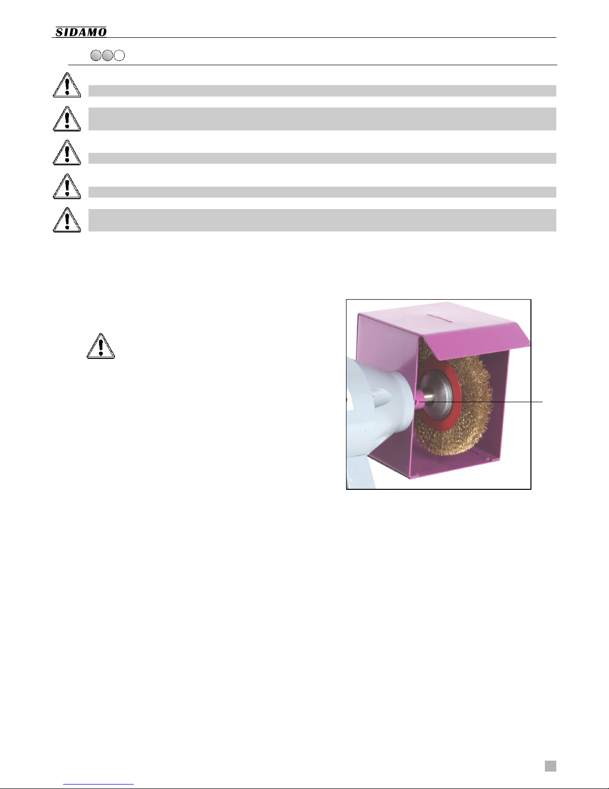
Procedure :
1. Make sure the equipment is switched off.
2. Block the driving shaft by matching, on the left side
of the wire wheel, the hole of the driving shaft with
the hole of the wire wheel guard (A).
3. Unscrew the wire wheel nut (18 fig.2) using an
open-end wrench.
4. The right nut is a right-hand nut. To
unscrew it, use anticlockwise direction.
5. Remove the outer flange of the wire wheel (3 fig.2).
6. Replace the used wire wheel (17 fig.2) with a new
one (make sure flanges and fitting shafts are clean
prior to fitting a wire wheel).
7. The hole of the wire wheel should perfectly fit the
shaft of the wire wheel-holder. If necessary, use
reduction bushes.
8. Fit the outer flange of the wire wheel.
9. Tighten the fixing nut, but do not apply excessive
torque. Because of its own inertia, this nut will tend
to self tighten.
A

User’s manual TM200B
14
8. ACCESSORIES AND CONSUMABLE PARTS
8.1. BASE S2
The bench grinder is designed to be fitted on a base S2
(optional).
Suction eight x Width x Depth
(mm)
Weight
(kg) Reference
S2 Not
included 845 x 360 x 360 13 20198075
8.2. BASE S2ASP
The grinder is fitted with two outlets to extract dusts.
It is possible to connect a base with a S2 ASP dust
extraction system.
Suction Power
(kW) Main power
Rotating
speed
(tr/min)
Air flow
(m³/h)
Depression
(mm 2O)
Noise
level
(dB)
eight x Width x Depth
(mm)
Weight
(kg) Reference
S2 ASP
included 0,15 1-phase
230 V 2800 290 95 75 845 x 360 x 360 25 20113033
8.3. DRILL S ARPENER
Additional drill sharpener, designed to be installed on
the bench, next to the grinder :
Sharpening of drills from Ø 3 mm to Ø 18 mm.
Angle adjustment range : from 41° to 88°.
Reference
Drill sharpener 20198072

User’s manual TM200B
15
8.4. W EELS AND WIRE W EELS
Genuine wheel/wire wheel :
Wheel AA 60 M : Ø 200 x 30 x 32 mm
(Reference : 10505063)
Brassed iron wire wheel : Ø 200 x 30 x 32 mm
(Reference : 10306012)
Available range of wheels/wire wheels :
Quality Description Application
A 24 R Fine grain grey corundum Dry deburring of ferrous metals,
removing rapidly large stock allowances
A 36 R Coarse grain grey corundum Dry deburring of ferrous metals,
removing rapidly large stock allowances
A 60 M Fine grain grey premium corundum
Finishing and sharpening of ferrous and
hardened metals (axes, sickles, drills,
burins, blades)
AA 60 M Fine grain white premium corundum Dry sharpening of hardened steels
(knives, scissors)
C 120 J Very fine green silicon carbide Dry sharpening of carbide and very hard
and hardened metals
Brassed
iron wavy
wire wheel
Better resistance of the wire to
deformation, because of the tension
force, lifespan is 30% longer than with
a steel wire
Pickling, cleaning, rust removing,
polishing of work pieces made from
ferrous/no ferrous metal, wood,
plastics
Stainless
steel wavy
wire wheel
To grind stainless steel and other non-
ferrous materials. No surface
blackening
Pickling, cleaning, rust removing,
polishing of work pieces made from
ferrous/no ferrous metal, wood,
plastics

User’s manual TM200B
16
9. SPARE PARTS
EXPLODED VIEW
Figure 2

User’s manual TM200B
17
PART LIST
N° Description Quantity Note
1
2
3
4
5
6
7
8
9
10
11
12
13
14
15
16
17
18
19
20
21
22
23
24
Left outer wheel guard
Wheel fixing nut
Flange
Washer
Wheel AA 60 M (Ø 200 x 30 x 32)
Left inner wheel guard
Protective shield
Spark screen/Shield-holder
Screws/Shield fixation
Tool-holder
Screws/Tool-holder fixation
Motor flange
Stator
Bearing
Rotor
Wire wheel guard
Wire wheel (Ø 200 x 25 x 32)
Wire wheel fixing nut
Switch
Power cable
Base
Plate
Electric plug
Capacitor
1
1
4
4
1
1
2
2
1
1
2
2
1
2
1
1
1
1
1
1
1
1
1
1
N° 1 + 6
N° 7 + 8 + 9
N° 20 + 23

User’s manual TM200B
18
10. ELECTRICAL CIRCUIT
ELECTRICAL DIAGRAM

User’s manual TM200B
19
11. NOISE LEVEL
All data related to the noise level of this machine, when
operating, depend on the type of material ground and on the
type of wheel used. That is why measurement data are only
relative.
The risk of hearing damage, for the operator, is related to
the noise exposure time.
The operator must wear soundproof headphones or any
convenient PPE when sound power is over 85 dB(A) at the
working place.
Equivalent, continuous, sound pressure level at the
working station :
LpA = 84,1 dB(A)
Sound power level :
LwA = 97,1 dB(A)
Calculating the sound pressure was performed considering
factors such as : reverberation of the test place, absorption
of noise at the ground level and other noises that can
interfere with the measures. The result is only an estimation
: nevertheless, one may say that, considering the values
obtained, the uncertainty would be about 3 dB(A).
The values given are those of emissions and do not
necessarily mean any safe working values. Although there is
a correlation between levels of emission and levels of
exposure, these values cannot be used with certainty to
determine whether additional measures are necessary.
Factors influencing actual levels of exposure are : the
properties of the working area, other noise sources, etc., i.e.
the number of machines and the type of processes used in
the vicinity of the machine. Also the highest acceptable
levels of exposure may vary in different countries. owever
this information should help the machine user evaluating the
risk and the risk rate in a better manner.
12. VIBRATIONS LEVEL
All data related to vibrations produced by this machine, while
machining, depend on the type of material ground and on
the type of wheel used. That is why measurement data are
only relative.
Average value of hand/arm vibrations :
Aw(8) < 2,5 m/s²
13. PROTECTION OF T E ENVIRONMENT
This machine is made from various materials that can be
recycled. This sign indicates that used equipment should be
discarded separately from other types of wastes.
Recycling these equipments will be best performed, in
compliance with the WEEE Directive 2012/19/EU on
waste electrical and electronic equipment.
ousehold users should contact their dealer or their local
government office for details of where and how they can
take this item for environmentally safe recycling.
Thank you for helping us protecting our environment.
14. GUARANTEE
Only authorized After-Sales Services are allowed to carry a
Guarantee. The Guarantee for this equipment is for 3 years,
starting from the date of purchase by the user.
As the invoice acts as a proof of valid Guarantee, we
recommend keeping it.
The purpose of the Guarantee is only to repair or replace,
free of charge, faulty parts, following an expertise performed
by the manufacturer.
The Guarantee will not cover any damage caused by the
user or a repairer non-authorized by the company SIDAMO.
The Guarantee will not cover any consequential or
subsequent damage, direct or indirect, material or
immaterial, caused to persons or things and resulting from
a failure or a shutdown of the equipment.
The Guarantee will not cover damages caused by :
Abnormal use.
Inappropriate operating.
Electrical modification.
A fault when transporting, handling or servicing.
The use of non-genuine parts or accessories.
Interventions performed by non-authorized persons.
The absence of any protection or device designed
to protect the operator.
The Guarantee of your machine is excluded in case on the
non-observance of above instructions.
The Buyer is responsible for the Goods during the transport.
Therefore the Buyer may exercise all judicial and
administrative remedies against the carrier, in the correct
form and within the legally required time.

User’s manual TM200B
20
15. DECLARATION OF CONFORMITY
« ORIGINALE » DECLARATION OF CONFORMITY
The undersigned (Manufacturer/Importer) :
SIDAMO
Z.I. DES GAILLETROUS – 41260 LA C AUSSÉE-SAINT-VICTOR - FRANCE
Declares that the new product described hereafter :
Description : BENC GRINDER-WIRE W EEL
Brand : SIDAMO
Model : TM 200 B
Reference : 20113104
Serial N° :
Complies with the essential safety requirements that apply to it :
Machinery Directive 2006/42/EC
Low Voltage Directive 2014/35/EU
EMC Directive 2014/30/EU
WEEE Directive 2012/19/EU
Ro S-2 Directive 2011/65/EU
REAC 1907/2006
Noise Directive 2003/10/EC
Vibration Directive 2002/44/EC
La Chaussée-Saint-Victor
Date :
JÉRÔME GERMAIN
Executive Officer
Person entitled to create the technical file :
M. GERMAIN – SIDAMO – Z.I. DES GAILLETROUS – 41260 LA C AUSSÉE-SAINT-VICTOR
Z.I. DES GAILLETROUS – 41260 LA C AUSSÉE-SAINT-VICTOR
Tel : 33 2 54 90 28 28 – Fax : 33 897 656 510 – Mail : si[email protected] – www.sidamo.com
Certified company ISO 9001 – ISO 14001
USER SERVICE
Tel : 33 2 54 74 02 16
It is SIDAMO’s policy to continuously develop and improve our products, and therefore we reserve the right to modify or
change the details at our discretion and without notice. Information, photos, exploded views and diagrams contained in this
document are not contractual.
Edition novembre 2017
User’s Manual TM200B
Table of contents


