Sideros DESIREE 760 Specification sheet
DESIRÉE 760
&
DESIRÉE 860
Instructions for use
and maintenance
GOOD WARMTH

2
INDEX
1Before installation............................ 2
1.1 Description ........................................ 2
1.2 Accessories........................................ 3
1.3 Technical data.................................... 3
1.4 Technical descriptions ....................... 3
2Installation instructions .................. 6
2.1 Assembling the side handrails ........... 6
2.2 Assembling the cover (optional)........ 7
2.3 General rules...................................... 7
2.4 Connection to the flue ....................... 9
2.5 Room ventilation ............................. 10
3Instructions for use ........................ 10
3.1 Introduction ..................................... 10
3.2 Suitable fuels ................................... 10
3.3 Lighting the stove ............................ 11
3.4 Operation in the transitional period .12
3.5 Operation during the winter period.. 12
4Cleaning and maintenance............ 12
4.1 Cleaning and maintaining the stove .12
4.2 Cleaning and maintaining the flue ... 13
Some suggestions for a good flue
1 BEFORE INSTALLATION
Thank you for choosing a SIDEROS product.
All parts of this product have been carefully made with the aim of meeting all safety
and functional requirements. To avoid any unpleasant problems and to make best use
of this appliance, please read this booklet carefully.
However, we recommend you always use a qualified installer.
1.1 DESCRIPTION
MAIN FEATURES
Wood-burning stove with dual combustion.
Body made of steel and enamelled sheet iron.
Firebox made of self-cleaning refractory bricks or cast iron.
Primary and secondary air control system.
Firebox with large panoramic door with self-cleaning ceramic glass.
Baffle plate with easy access for cleaning and regular inspection.
Faced entirely in ceramic.
Enamelled cast iron hob with a set of rings for cooking and (optional) cover.
Grate shaker.
Smoke control valve for heating the oven.
Multi-purpose 32 L (Desirée 760) and 46 L (Desirée 860) oven
Food warmer compartment
Wood storage compartment
3
1.2 ACCESSORIES
Before setting the stove up, check that all the accessories have been included:
- poker
- collar Ø120 (Desirée 760) and Ø130 (Desirée 860)
- R & L side handrails
- protective glove
- additional documentation (Guarantee, flue booklet, ANFUS booklet, guarantee
centres booklet)
N.B.: The additional documentation should be read and kept!
1.3 TECHNICAL DATA
TAB. 1
Manufacturer: Sideros S.p.A.
41038 San Felice S/P (Italy)
Model: DESIRÉE 760 DESIRÉE 860
Back 200 mm
Side 300 mm
Distance from walls:
Front 800 mm
Flue diameter: 120 mm 130 mm
Flue position: Top - Back
Dimensions:
Width cm 75 86
Depth cm 60 65
Height cm 85 85
1.4 TECHNICAL DESCRIPTIONS
The Désirée stoves have been designed to heat rooms in houses or flats or improve
inadequate heating while, at the same time, enhancing the appearance of every room.
The body of the stove is made of very thick steel and enamelled sheet iron that give
long-term solidity to the product. The hob and the firebox, oven, food warmer and ash
pan doors are in RAF enamelled cast iron.
On the top there is a set of cast iron rings that can be used to cook and/or heat food.
Under the oven there is a food warmer compartment with its own small door. NEVER
put inflammable materials inside it!
In the bottom part of the stove there is a drawer for storing wood.
Desirée can have a firebox made of cast iron or refractory bricks.
On all versions there is a grate shaker hidden behind the ash pan door (FIG. A).

FIG. A
Grate shaker
The firebox has a panoramic door with ceramic glass that withstands high
temperatures (700°C). With this solution, we wanted to offer the visual appeal of
flames inside the firebox without any danger of sparks or smoke escaping into the
heated room. The firebox door and the ash pan door are air tight. Fuel is loaded by
opening the firebox door from R to L. It is opened by releasing the HANDLE to the R
of the firebox door.
When loading wood, we recommend you are very careful with the refractory
bricks in the firebox (in the versions with the firebox made of refractory bricks) as
they could break if knocked hard. Remember that improper use of the stove (too
much fuel, etc) will wear out the stove more quickly so use the amount of fuel
appropriate to the heating capacity of the appliance.
We advise always taking great care and using the protective glove provided when
loading fuel and inspecting the ash pan.
Heating is obtained by convection, through the air passages situated between the body
of the stove and the ceramic side panels and through the openings at the front and the
back of the stove, and by irradiation using the heat from the glass door, the external
ceramic walls and the cast iron parts.
Both versions of the stove have the same dual air intake control system with a
primary air valve and a secondary air valve.
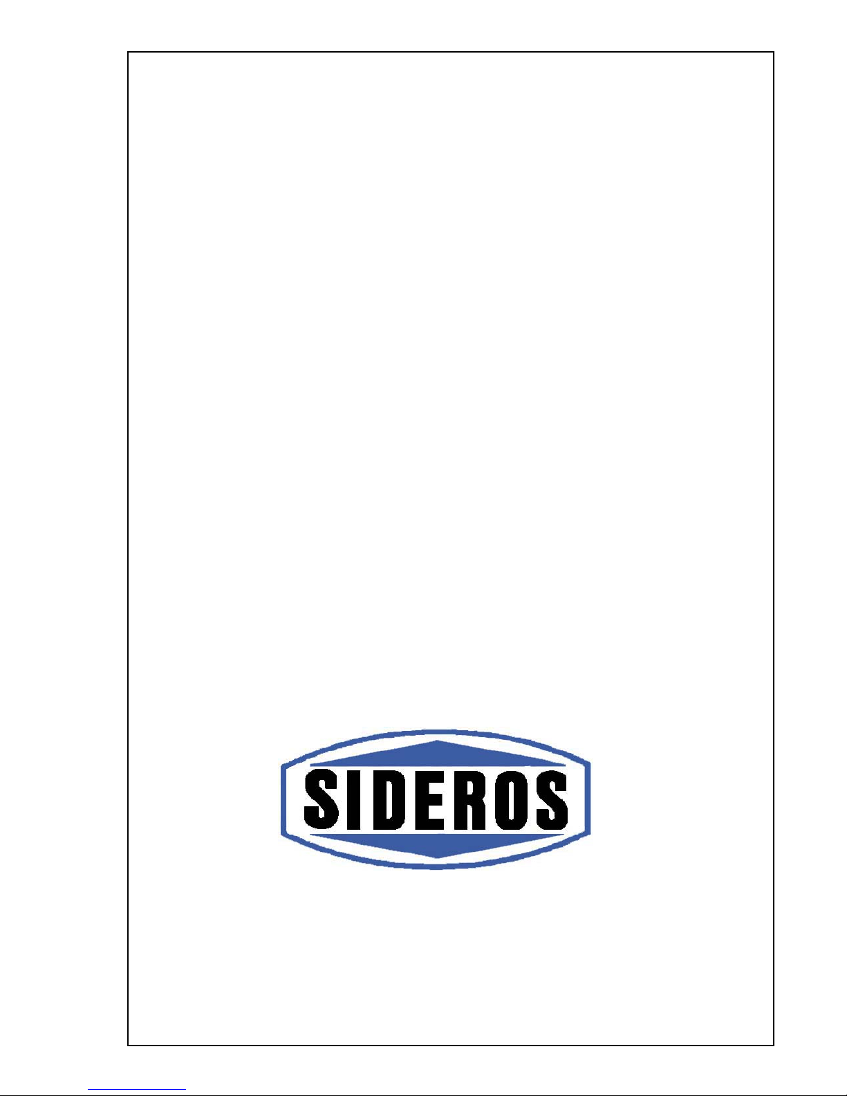
The primary air valve (FIG. B and FIG. C) is in the centre of the ash pan door. This
valve allows air to come in from below, through the ash pan area, the grate holder and
the grate towards the fuel. The primary air (P.A.) is vital for combustion. Therefore,
avoid overfilling the ash pan placed immediately under the grate, as the ash can
obstruct the entry of the primary air.
The intake is controlled by moving the controls in the middle of the ash pan door
from right to left or vice versa.
The position for maximum intake of primary air is when the top control is completely
at the right (FIG. B), whereas, on the other hand, the valve is closed when the top
control is completely at the left (FIG. C).
4
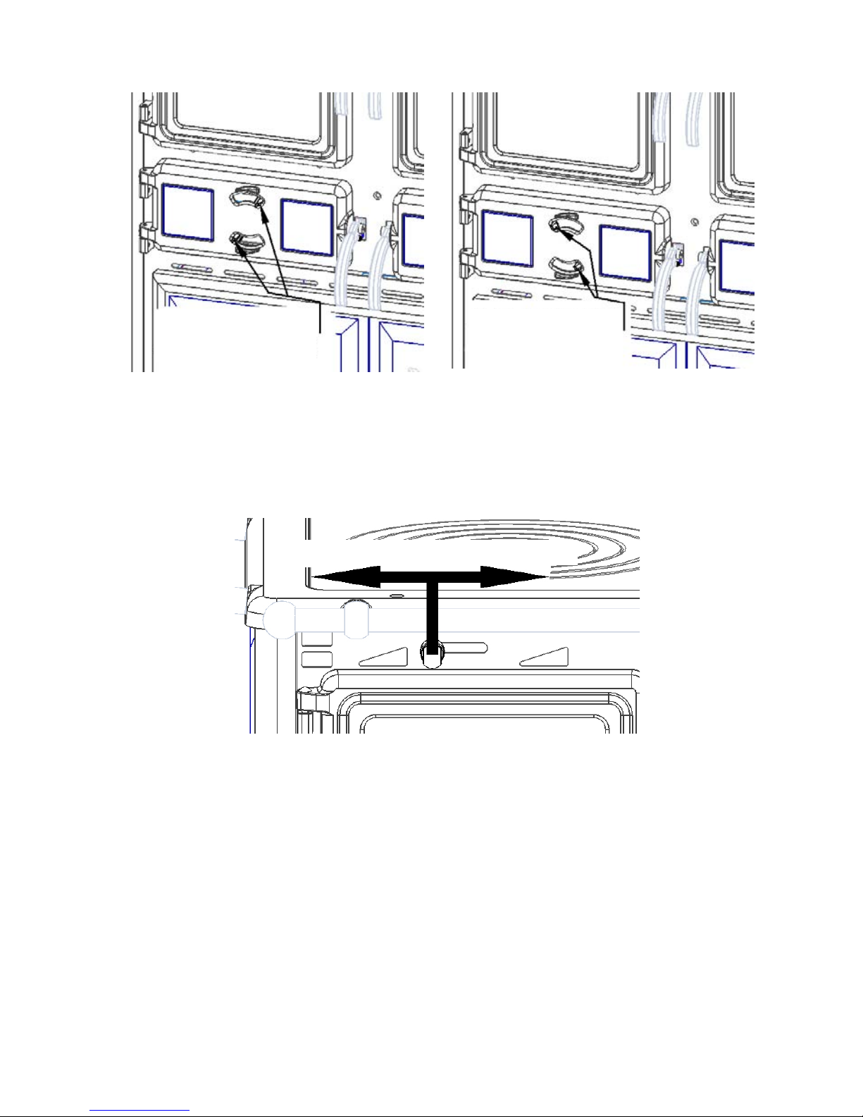
FIG. B FIG. C
PRIMARY AIR
CLOSED
PRIMARY AIR
FULLY OPEN
The secondary air valve (FIG. D) is above the firebox door and allows air to come in
from the top of the firebox, substantially improving combustion. This second intake of
air also helps keep the glass of the firebox door clean. It is controlled by moving the
KNOB above the firebox door: turning it from L to R increases the air intake
whereas the reverse reduces it until it is completely closed.
FIG. D
CLOSED OPEN
For good combustion and to avoid overheating the stove and using too much fuel, it is
advisable to use the settings given in TAB. 5 ch. 3.5.
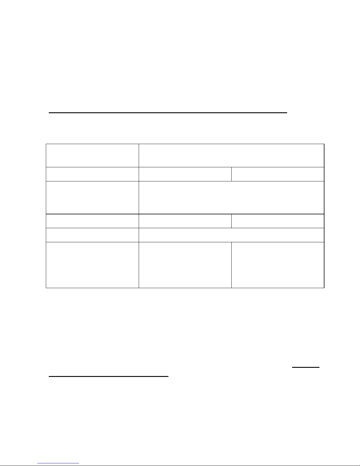
There is a smoke control valve on the Désirée stoves that can be used in several
positions. This valve is on the R side of the stove, above the firebox door and under
the cast iron hob. When it is in the open position (FIG. E) the smoke can take the
shortest route to the flue and this makes lighting the appliance easier. The other
positions of the valve are used to control the degree of opening and send the flow of
hot fumes to heat the multi-purpose oven (closed position FIG. F).
5
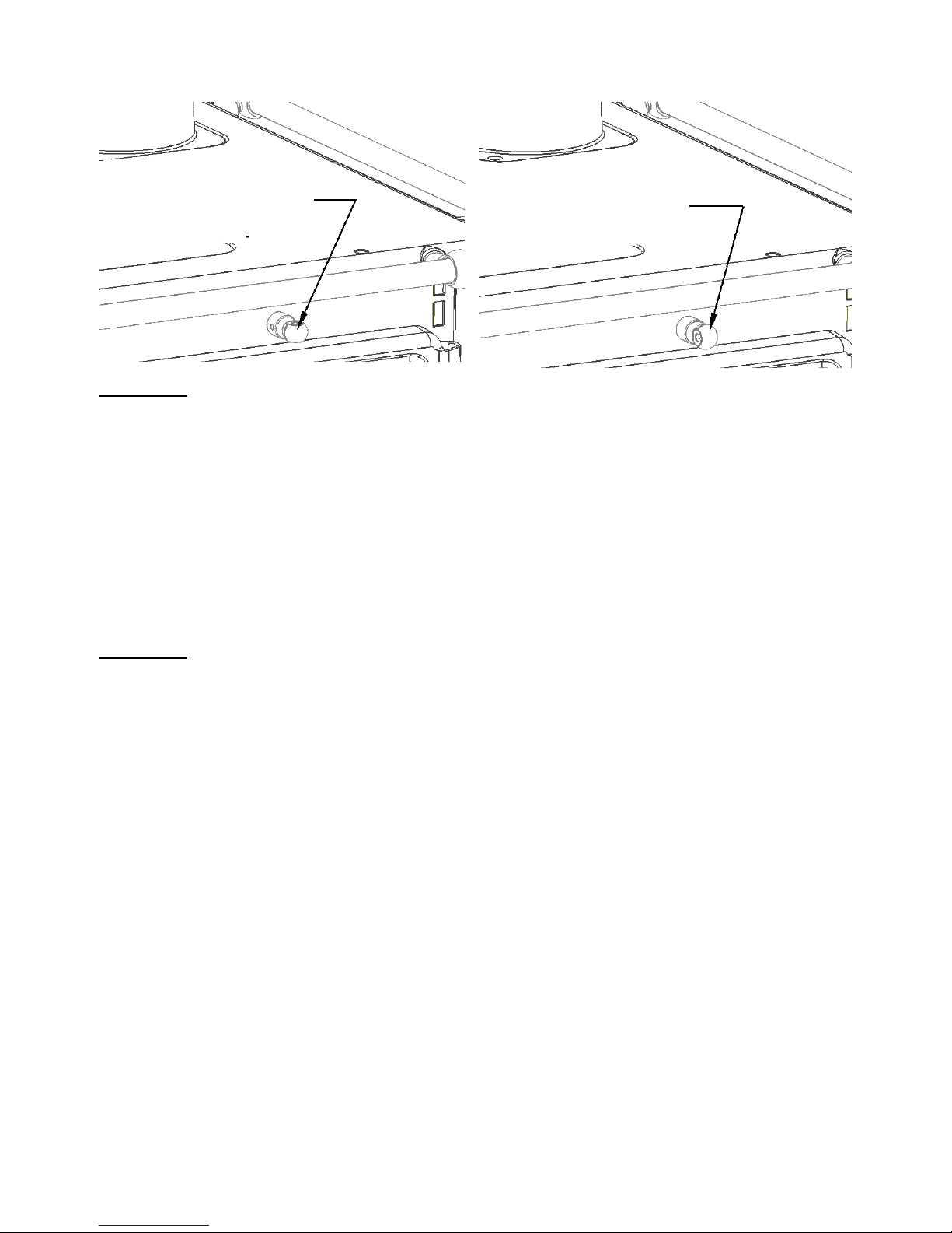
FIG. E FIG. F
Smoke control
valve knob
Open position
Smoke control
valve knob
Closed position
!Beware!: To change the smoke valve knob from one position to the other, press it in
towards the stove, then turn it clockwise to move from closed to open, and vice versa,
it is necessary to turn it anticlockwise to close the valve.
The multi-purpose ovens, in enamelled sheet iron, have a glass door that withstands
high temperatures. In the Desirée 760 the oven has a capacity of 32 L, whereas the
Desirée 860 has a capacity of 46 L. The oven is heated by induction from the walls in
contact with the hot fumes, guaranteeing a temperature of 250° in the middle of the
oven. The internal temperature can be seen from the thermometer visible in the central
part of the glass door. The oven is opened by opening its door from L to R. It can be
opened by releasing the HANDLE to the L of the oven door.
To avoid heat loss while cooking food, open the oven door as little as possible.
!Beware!: We recommend using theprotective glove provided whenever you need
to do anything to the hot parts of the stove.
2 INSTALLATION INSTRUCTIONS
2.1 ASSEMBLING THE SIDE HANDRAILS
You will find the side handrails in the wood storage compartment and they are
assembled as follows:
- take the handrail marked L (1) and fix it to the left side of the stove; do the same to
the rail marked R (2) which will be fixed to the right side of the appliance.
- The 2 pins (3) protruding from the handrail must be put into the 2 bushes (4) on the
cast iron hob.
- Having done this, to hold the handrails (1) and (2) in position, take the M5 grub
screws (5) that you will find in a plastic bag in the wood storage compartment, and
screw them onto the bushes through the hole at the bottom of them.
6
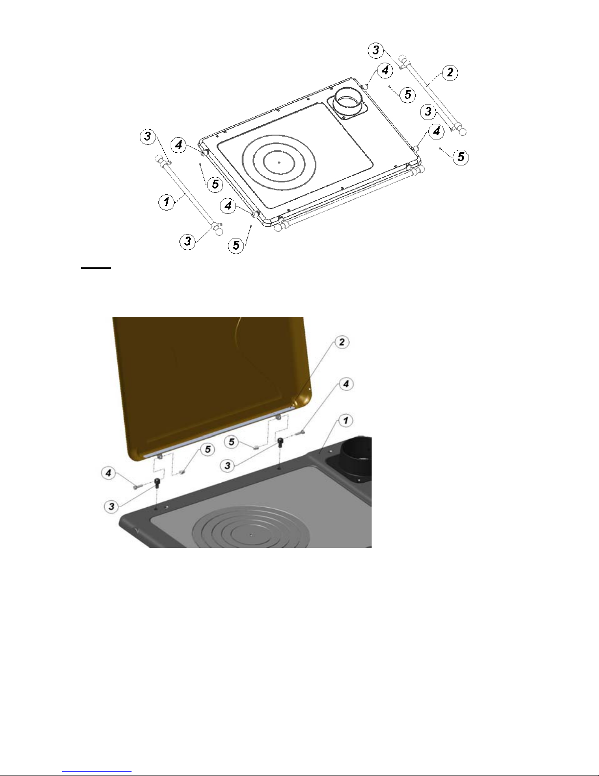
KEY: (1) L Handrail, (2) R Handrail, (3) Handrail Pin, (4) Handrail Bush,
(5) M5 Grub Screw.
2.2 ASSEMBLING THE COVER (OPTIONAL)
1- FRAME
2- COVER
3 - PINS TO FASTEN THE
COVER
4- HH SCREWS M 6x20
5- M6 CAP NUTS
To attach the cover to the
frame of the stove, proceed
as follows:
Screw the pins (3) fully into
the holes cut in the frame
(1). Bring the cover (2) close
to the pins (3). Insert the
threaded screws (4) fully
into the holes of the pins (3)
and then into the holes in the two eyelets attached to the cover (2). Put the cap nuts on
and tighten fully.
N.B.: When the threaded pins (3) are completely tightened, the cover can be opened
around 5° at the back. It can be opened more by not tightening the pins completely.
2.3 GENERAL RULES
Some general instructions must be followed when installing the stove:
- The appliance generates heat especially near the firebox so no inflammable or very
heat-sensitve object (e.g. alcohol, paper, plastic items, etc) should be placed near the
stove.
- Keep the stove away from the walls or other secondary protection according to the
measurements in TAB. 1 ch. 1.3 (minimum measurements).
7
- Ensure that the place or room where the stove is to be installed is adequately
ventilated (see ch. 2.5).
- Once the best position has been determined, unpack the stove removing the
cardboard and the internal protective material.
- Check that the doors open and close properly.
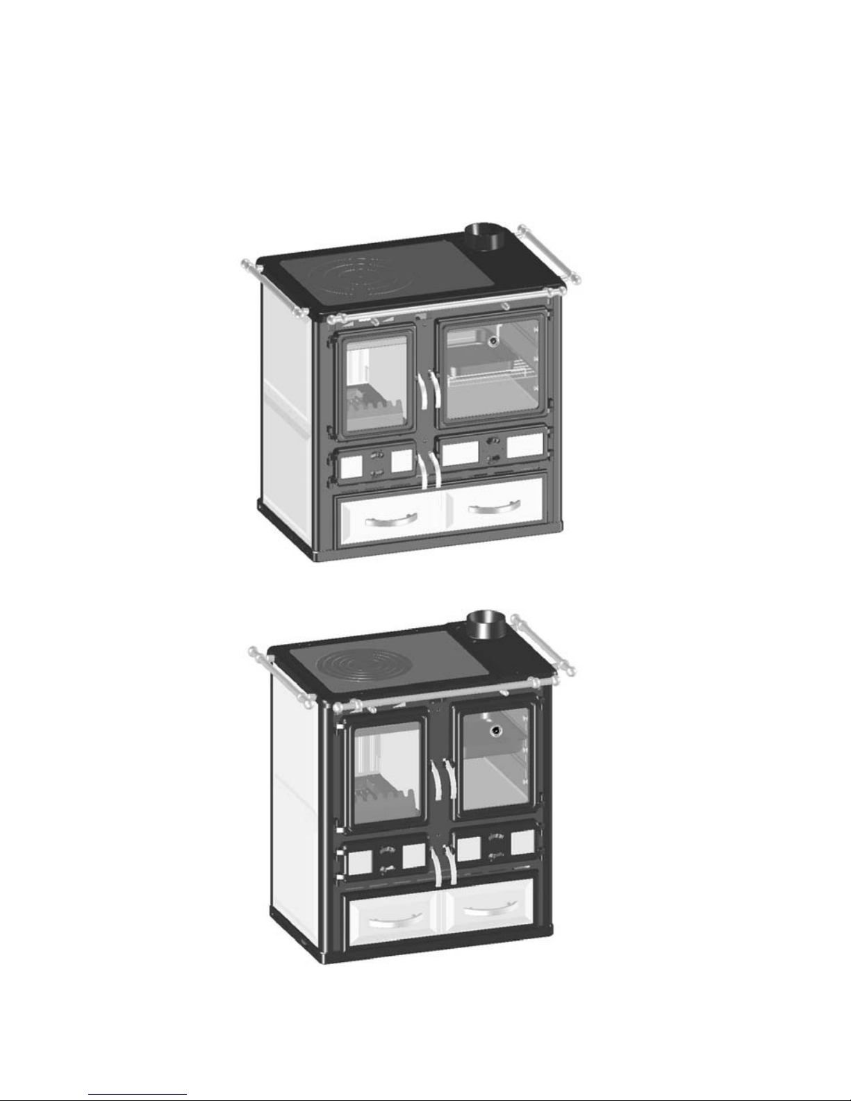
FIG. G (Desirée 860 Version)
FIG. H (Desirée 760 Version)
8

9
2.4 CONNECTION TO THE FLUE
It is good to remember at all times that it is at least as important that the flue works
correctly and is used safely as that the stove does.
Ensure that the flue draught is between 0.10 mbar and 0.15 mbar, if it should be
lower, check that it complies with current rules (UNI EN 1443 and UNI EN 10683).
It is vital that these standards are complied with for modern high-performance
appliances to operate correctly as they discharge smoke into the flue at a substantially
lower temperature than old low-performance appliances.
For this reason, we recommend that the stove is installed by a qualified
person in accordance with current standards and regulations.
!BEWARE!: any excess draught (constantly above 0.20 mbar for a period of time)
will cause damage due to excessive wear to the whole body of the stove and the baffle
plate, as well as poor heat efficiency.
The stove is connected to the flue by flue pipes of Ø 120 mm (Desirée 760 version)
and Ø 130 mm (Desirée 860 version). These pipes are available on the market and are
connected with the collar provided.
The stove comes with the flue outlet at the top. The collar is in the ash pan drawer
and must be assembled and fixed with the M5 screws on the hob.
To use the rear flue outlet follow the following instructions:
- remove the cut-out on the back of the stove corresponding to the blanking plate,
working on alternative sides of it until it comes out;
- remove the rear flue outlet blanking plate by loosening the screws;
- remove the collar from the top flue outlet position, loosening the screws, and
position it where the rear flue outlet blanking plate was;
- tighten the collar using the screws taking care to position the sealing ring
carefully;
- then fasten the blanking plate in the top flue outlet position tightening the screws
fully.
When using the top flue outlet, to obtain the best draught, the first vertical
length of flue from the stove must be at least 1 metre long. Furthermore, it is
important that the stove - flue connection is made with a maximum horizontal
length of 1 metre. Should the horizontal lengths be longer than a metre, there
must be a slope of at least 10 cm for every metre of pipe.
When using the rear flue outlet, it is preferable that the flue inlet should be in
line with the stove’s flue outlet, thereby avoiding any bends in the piping that
would reduce the draught of the stove and slow down the discharge of the smoke,
thus causing the stove not to work well. Check that the pipes are properly sealed
so that no smoke can escape and check that the length of tube entering the flue
does not obstruct the passage of the smoke. In any case, it is better to place the
stove near the flue to avoid long lengths of pipe that would reduce the flue
draught.
To check the flue draught, consult the following TAB. 2.
10
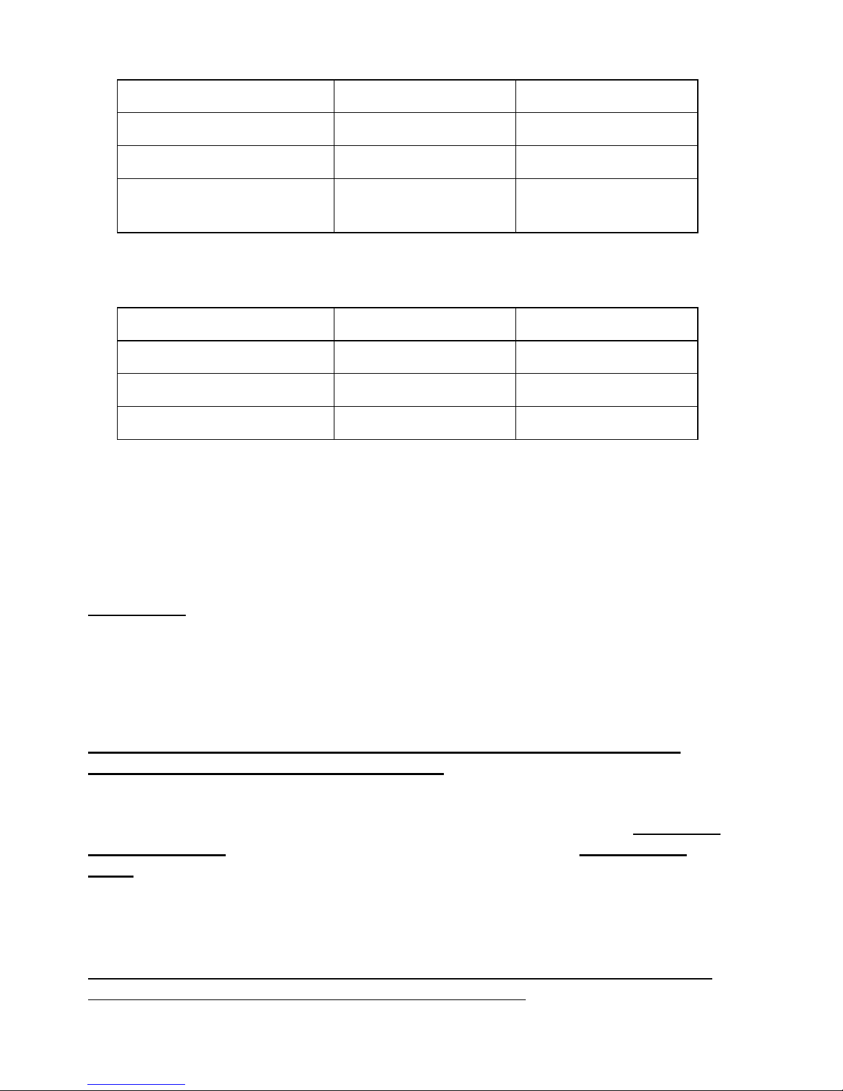
TAB. 2
STOVE MODEL DESIRÉE 760 DESIRÉE 860
Rated output 6.5 kW 7 kW
Flue temperature 190 °C 200 °C
Negative flue pressure at
max output 0.12 mbar 0.12 mbar
Room heating capacity (for buildings whose insulation does not meet heat protection
regulations).
TAB. 3
HEATABLE VOLUME DESIRÉE 760 DESIRÉE 860
Good conditions 148 m3160 m3
Normal conditions 88 m395 m3
Poor conditions 60 m365 m3
2.5 ROOM VENTILATION
To ensure that the stove works well, it needs to be in an adequately ventilated room to
enable the stove to supply the amount of air needed (20 m3/hour) for the fuel to burn
completely without gas residues and at the rated output.
3 INSTRUCTIONS FOR USE
WARNING.
In view of the high temperatures reached by the stove, adults and children must be
careful with the surfaces of the stove. Children must be watched very carefully.
In an emergency, close all the air controls thereby smothering combustion. Then
remove the wood from the firebox using TONGS INTENDED SPECIFICALLY
FOR THIS TASK.
N.B.: It is absolutely forbidden to throw water on the stove when it is lit and
when cooling down to prevent any breakages.
3.1 INTRODUCTION
Do not place any inflammable or heat-sensitive objects near the stove and always and
on every occasion when the stove is lit, for whatever purpose, use the protective
glove.
3.2 SUITABLE FUELS
We advise using the following fuel in the stove:
- Dry (15/20 % humidity), natural wood (beech, birch or oak) chopped into pieces.
It is absolutely forbidden to burn rubbish or any other treated product whatever that
may produce gases harmful to the environment or to health.
The ideal quantities of fuel with the door closed are given in TAB. 4.
11
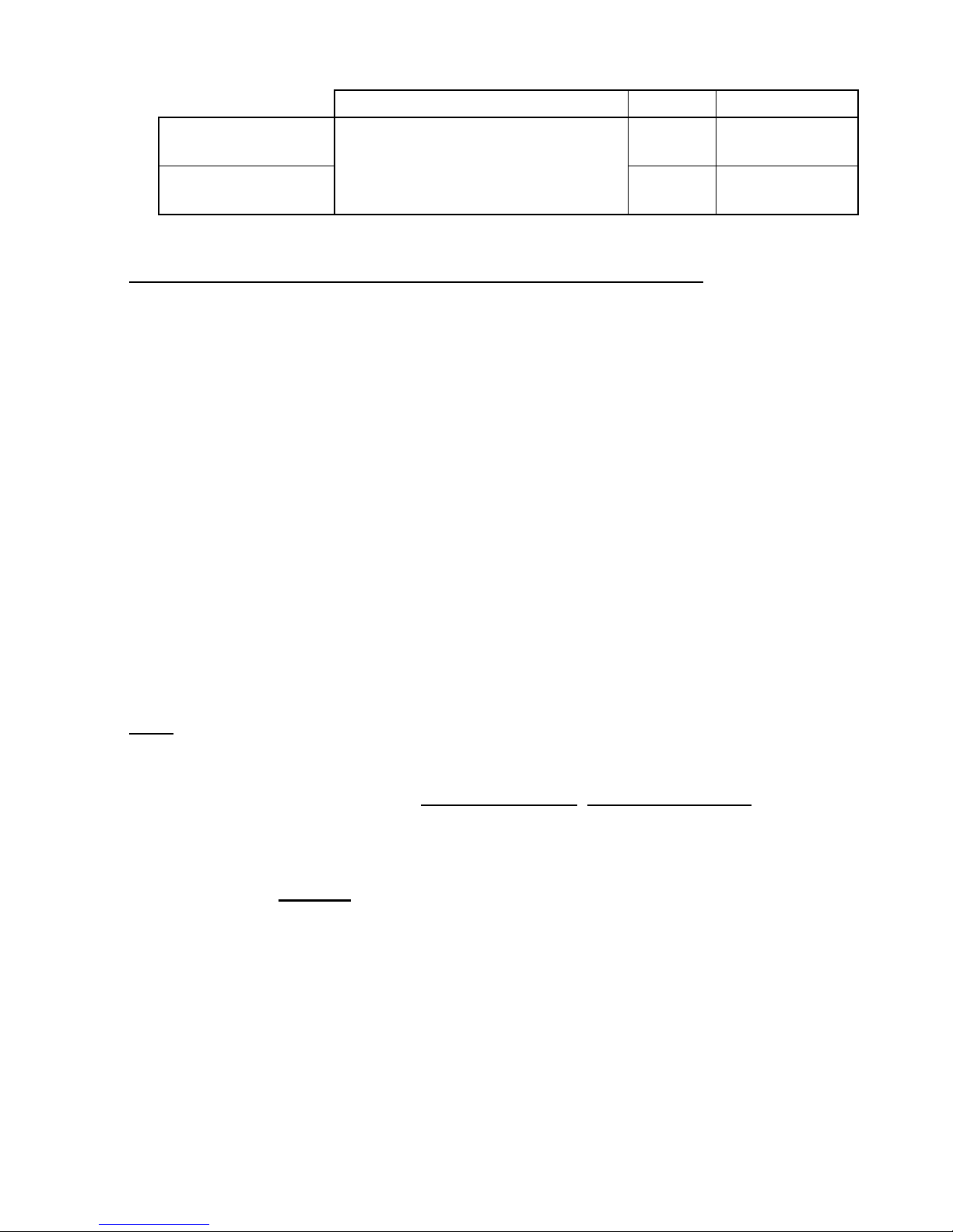
TAB. 4
TYPE OF FUEL kg N° Pieces
DESIRÉE 760 2.0 2 medium
3 small
DESIRÉE 860 Wood
2.25 2/3 medium
3/4 small
3.3 LIGHTING THE STOVE
The lighting stage is very important especially the first few times.
To carry out this stage properly, follow the following rules:
- open the windows or ensure good ventilation in the room somehow;
- check that there are no foreign bodies inside the firebox, the ash pan and the food
warmer compartment;
- close the secondary air valve and open the primary air valve fully;
- put two or three sheets of paper or 2pieces of firelighter (e.g. Diavolina) in the
firebox;
- when using paper, cover it with some thin pieces of wood and on top of these,
2thicker pieces of wood;
- light the paper from below the wood and close the firebox door;
- when using firelighters, wait until they are fully alight before putting in thin pieces
of wood and 2 thicker pieces on top of them (this helps the initial movement of air
inside the firebox);
- wait a few moments until the fire takes hold, then open the secondary air valve to ¼
open;
- when the fire is lit, control the primary air and the secondary air according to the
desired output;
- choose the combination of settings for the comburent air from TAB. 5.
N. B. It is always good to keep the Secondary Air valve at least ¼ open while the fire
is lit to keep the ceramic glass clean and prevent the front of the area above the firebox
door from overheating.
However, in any situation with a poor flue draught, NEVER EXCEED the
quantity of fuel in the lighting stage because this could cause an excessive increase
in smoke resulting in obstruction and undesired emissions of smoke from the valves.
- During normal operation, keep the firebox door closed at all times.
To light the fire, NEVER use easily inflammable liquids such as petrol or alcohol.
The first 2 or 3 times you light the fire, keep it at a moderate heat to allow the stove to
settle down evenly without sudden changes in temperature.
- The ash pan is big enough to collect all the ash from the grate, thus avoiding it
spreading to the storage compartment.
N.B.: AFTER THE FIRE HAS BEEN LIT, FUEL SHOULD BE ADDED WHEN
THERE IS A LAYER OF EMBERS AND NO FLAMES INSIDE THE
FIREBOX. THIS WILL PREVENT SMOKE ESCAPING WHILE ADDING
FUEL AND WILL OPTIMIZE FUEL CONSUMPTION.

12
3.4 OPERATION IN THE TRANSITIONAL PERIOD
During the low season, the draught can be compromised in view of the fact that
external temperatures can easily go above 15°C the point when it is advisable to clean
the grate properly before lighting in order to have a better flow of air below the grate.
In addition, to ensure the stove works better it is preferable to use less wood, to clean
the grate frequently with the poker and rekindle the embers by using the grate shaker.
3.5 OPERATION DURING THE WINTER PERIOD
Each time before you light the fire, always remember to remove the ashes from the
grate. If there are embers in the firebox, spread them evenly over the grate so that the
primary air can reach everywhere: in this way there will be greater efficiency. Once
the stove is lit, control the primary air depending on the heat wanted and the amount of
fuel used (much fuel = + primary air – secondary air; little fuel = - primary air +
secondary air). To maintain optimal efficiency refer to TAB. 4 ch. 3.2 and the
following TAB. 5.
TAB. 5
TYPE OF FUEL: WOOD DESIRÉE 760 DESIRÉE 860
Output control Rated output Rated output
Primary air ¼ Open ¼ Open
Secondary air ½ Open ¾ Open
4 CLEANING AND MAINTENANCE
4.1 CLEANING AND MAINTAINING THE STOVE
Before carrying out any cleaning operation, wait until THE STOVE AND THE
PIPES connecting it to the flue have COOLED DOWN COMPLETELY.
To clean the external ceramic and enamelled sheet iron parts, use a soft cloth and
liquid detergent. Never use steel wool or abrasive sponges with metal parts as they can
ruin the surface.
To clean the glass of the firebox door we recommend using liquid detergents rather
than powders, usually used to clean cooking surfaces or enamelled sinks.
To avoid scratching the surface of the glass, never use abrasive sponges.
To clean the cast iron parts we recommend using a cotton cloth dampened with hot
water after brushing the surfaces with a small brush to remove the fine dust.
NEVER use inflammable products.
To clean the firebox, clean the grate with the poker and use the grate shaker so that
all the residual ash falls into the ash pan drawer. The ash pan drawer is reached
through the door immediately below the firebox door. When emptying the ash pan
drawer, always leave a thin layer of ash a few millimetres thick at the bottom of the
drawer. The ashes must be tipped into a fireproof container to avoid any danger should
gases or inflammable vapours develop as the result of the combustion of
unrecommended materials.

13
4.2 CLEANING AND MAINTAINING THE FLUE
Every year, normally before the autumn, it is necessary to have the flue cleaned by a
qualified person to remove soot deposits, unburnt oils and other possible obstructions
that might have developed and to check the condition of the flue itself (for possible
holes, cracks, infiltrations, etc.).
At least twice a year also clean the pipes connecting the stove to the flue and if
necessary replace them if they are no longer fit to be used.
SOME SUGGESTIONS FOR A GOOD FLUE
A flue for discharging combustion products from natural draught appliances into the
atmosphere must meet the following requirements:
- be adequately heat insulated;
- be made from suitable materials to last a long time;
- have a chamber to collect solids and any condensates beneath the inlet of the first
flue pipe
- be at least 4 m high from the floor on which the appliance is placed;
- have a chimney pot at the top;
- not have any mechanical means of creating a draught above the top of the flue;
- be made in such a way that the openings, both inside and outside the walls,
cannot be obstructed, for example with grates, wire netting, etc. so that the
effective area indicated above is not reduced;
- be positioned at a height close to the level of the floor so as not to cause any
hindrance to the correct operation of devices for discharging combustion products.
- in a flue that passes through or is placed against inhabited rooms, there must not be
any excess pressure.
If an old flue that is too big has to be used, it can be adapted by inserting a stove pipe
inside, taking care to close the air gap created.
The chimney pot must be professionally made and must meet the following
requirements:
- have an effective outlet area not less than double that of the flue on which it is
placed;
- be shaped in such a way as to prevent rain or snow entering the flue;
- be made in such a way, that from whatever direction and angle the wind comes, the
combustion products are certain to be discharged in every case.
The top of the chimney must be above the down draught area. This area follows the
shape of the roof and depends on how much it slopes: the more it slopes, the bigger it
is (min 0.5 m - max 2.10 m).
The connection between natural draught appliances and a flue is made with flue
pipes. These must have the following requirements in addition to those mentioned in
ch. 2.4:
- at any point of the flue pipe and in whatever external conditions, the smoke
temperaturemust be higher than the dew point;
- be visible, easy to dismantle and installed in such a way as to allow normal thermal
dilation;

14
- have no more than three changes of direction, including the connection to the flue
inlet, made with internal angles of not less than 90°. The changes of direction must
be made using only curved elements.
- have the final length to the flue inlet perpendicular to the opposite internal side of
the flue;
- the flue pipe must also be solidly sealed to the flue inlet, without protruding inside
it;
- have along its whole length, an area no smaller than that of the connection of the
appliance’s flue outlet pipe. In the event that the flue has a diameter smaller than that
of the flue pipe, a conical connection must be made to match the inlet;
- be at least 0.5 m away from combustible or inflammable materials; if this
distance cannot be maintained, suitable heat protection must be provided.
It is vital that in rooms in which natural draught appliances are installed, at least as
much air as is needed for normal combustion in the appliance and for the ventilation of
the room must be available.
- have a total net free area of at least 6 cm² for every kW of heat supply installed,
with a minimum of 100 cm²;
- be made in such a way that the openings, both inside and outside the walls, can be
protected, for example with grates, wire netting, etc. so that the effective area
indicated above is not reduced;
- be positioned at a height close to floor level so as not to prevent devices for
discharging combustion products from working properly.
The air intake can also be obtained from an adjacent room provided that:
- it has direct ventilation, in accordance with the points described above;
- it is not used as a bedroom;
- it is not a room with a fire danger, such as a shed, garage, or storeroom for
combustible materials, etc.
- it does not have negative pressure compared to the room to be ventilated because of
an opposite draught (that may be caused by the presence in the room either of
another fuel-burning appliance or any suction device, for which an air inlet is not
provided).
- The air flow from the room next to the room to be ventilated can flow freely through
permanent openings, with a total net area no smaller than that indicated previously.
- To use the flue correctly refer to standards UNI EN 1443 and UNI EN 10683.

15
Blank page

THE MANUFACTURER REJECTS ALL LIABILITY FOR INJURY TO
PEOPLE, ANIMALS OR THINGS CAUSED BY NOT ABIDING BY THE
GENERAL SAFETY STANDARDS AND THE INSTRUCTIONS FOR
USE, CLEANING AND MAINTENANCE PRESENTED IN THIS
MANUAL.
Sideros S.p.A.
Via dell’Industria, 87
41038 San Felice sul Panaro
MODENA ITALY
Tel. 0535/8.66.11 Fax. 0535/8.66.45
E-mail: info@sideros.com
Website: www.sideros.com
The technical data given is indicative and not binding.
The manufacturing company reserves the right to modify the product in line with technical
developments, without notice (decree of 24/03/78).
Code 086.951593.00 published September 2005
This manual suits for next models
1
Table of contents
Other Sideros Wood Stove manuals

Popular Wood Stove manuals by other brands


Heta
Heta Scan-line 7 Series Operating and installation instructions

FRANCO BELGE
FRANCO BELGE ARDENNES 134 13 15 Technical manual

Teba therm
Teba therm TKS-19 installation manual

Avalon
Avalon Pendleton 745 owner's manual

FRANCO BELGE
FRANCO BELGE Bourgogne Technical manual

Romotop
Romotop EVORA Series manual

Waterford
Waterford Erin 90 T/V Installation & operating instructions

Russo
Russo 1 C/W manual

Morsø
Morsø 1410 Instructions for installation and use

Travis Industries
Travis Industries LOPI Liberty owner's manual

Dimplex
Dimplex SKG20 Installation and operating instructions

Quadra-Fire
Quadra-Fire 57ST-ACC installation guide