Sideshift SS Series User manual

BOW & STERN
THRUSTER
INSTALLATION MANUAL
SS/ST/WB/230/240/340/350 SERIES
VOLUME 2.7, JULY 2023
Sideshift Inc. 130 Industrial Ave, Unit 303, Carleton Place, ON, Canada K7C 3T2
1.877.325.4787 +613.686.6011 INFO@SIDESHIFT.CO

SIDESHIFT INSTALLATION GUIDE V2.7
1
INTRODUCTION
Thank you for your purchase of a Sideshift thruster system.
Sideshift thrusters are designed for easy installation by anyone with basic mechanical
and electrical skills.
This manual explains everything you need to know about installing your Sideshift
thruster.
We also provide unlimited telephone support at
1.877.325.4787. or +1.613.686.6011
See our website for helpful installation videos at
Installation - Sideshift Bow Thrusters and Stern Thrusters
This manual explains the different types of thrusters, the parts, tools and procedures
required to install them, the electrical system that supplies power to the thruster
motors, as well as maintenance and troubleshooting procedures.
We recommend that you familiarize yourself with the entire manual before starting
your installation.

SIDESHIFT INSTALLATION GUIDE V2.7
2
Safety warnings
WARNING: Ensure thruster battery switch and main ignition are turned off
when conducting maintenance and repair of the thruster.
WARNING: Use extreme caution when swimmers are in the area of the thruster.
Turn off ignition and avoid contact with thruster props when boat is
stationary.
WARNING: For optimal thruster performance and to prevent overheating
operate the Sideshift thruster in short bursts of 3-5 seconds at a
time as a standard practice. Never run for more than 30 seconds at
a time.
WARNING: When operating out-of-water do not run thruster for longer than
5 seconds to prevent overheating.
WARNING: If conducting an in-water installation, use a cordless drill only, as a
corded drill can present an electrocution hazard.

SIDESHIFT INSTALLATION GUIDE V2.7
3
MODEL TYPES
There are two basic types of Sideshift thruster systems covered in this manual:
fixed-mount bow thrusters and fixed-mount stern thrusters.
Electrical connections and controls for both types are similar, however placement
and mechanical attachment details vary between the two types of thrusters.
Our SS/ST series thrusters do not retract or deploy. They are permanently fixed to
the boat and rise out of the water when the boat planes, creating no drag. They also
work well on displacement type hulls and will create no noticeable drag, nor will they
affect handling.
Bow Thruster Models
Model
Suitable Boat Length
V DC
Max
Current
HP
Props
SS230
20-35 ft. (6.1 –10.7 m)
12
300 A
2.5 HP
Single prop
SS340
30-45 ft. (9.1 –13.7 m)
12
550 A
5.0 HP
Dual prop
SS350
40-60 ft. (12 –18.3 m)
24
400 A
7.5 HP
Dual Prop
Transom-Mount Stern Thruster Models
Model
Suitable Boat Length
V DC
Max
Current
HP
Props
ST/WB230
20-30 ft. (6.1 –9.14 m)
12
300 A
2.5 HP
Single prop
ST340
20-45 ft. (6.1 –13.7 m)
12
550 A
5.0 HP
Dual Prop
ST350
40-60 ft. (12.2 –18.3 m)
24
400 A
7.5 HP
Dual Prop
Outboard/Outdrive-Mounted Stern
Thruster Models
Model
Suitable Boat Length
V DC
Max
Current
HP
Props
ST230
20-30 ft. (6.1 –9.14 m)
12
300 A
2.5 HP
Single prop
ST230-Dual
30-40 ft. (9.14 –12.2m)
12
500 A
5 HP
Dual prop
ST240-Dual
35-50 ft. (10.7 –15.24m)
24
400 A
7.5 HP
Dual prop

SIDESHIFT INSTALLATION GUIDE V2.7
4
PARTS AND TOOLS
Bow Thruster Parts
Item
Photo
Purpose
Bow cover
Secures thruster base to hull.
Covers and protects through-hull
connections
Bow thruster base with
motor
Propeller and motor
Clamp Strap
Secures thruster base to hull.

SIDESHIFT INSTALLATION GUIDE V2.7
5
Center Bolt
Attaches clamp strap to thruster
Lock Nut (1)
Locks center bolt in place
Threaded hull insert and
bolts (2)
Secures clamp strap assembly to
hull.
Hull insert epoxy kit
Cements threaded hull inserts in
place

SIDESHIFT INSTALLATION GUIDE V2.7
6
Top through bolt
assembly
Secures top of upper section
Side screws (2)
Secures upper section cowling

SIDESHIFT INSTALLATION GUIDE V2.7
7
Stern Thruster Parts
Item
Photo
Purpose
Stern thruster base with
motor
L Bracket
Attaches stern thruster to
transom
Swim Platform Extension
Bracket
Attaches stern thruster to
underside of swim platform

SIDESHIFT INSTALLATION GUIDE V2.7
8
Common Parts
Item
Photo
Purpose
Joystick (single)
Controls bow or stern thruster.
Joystick (Dual)
Dual control for bow and stern
thruster.
Motor Controller
Switching solenoid for turning
thruster on and off.

SIDESHIFT INSTALLATION GUIDE V2.7
9
Threadlocker/Anti-seize
Prevents screw and bolt threads
from seizing, facilitating easier
assembly and disassembly.
Heat shrink tubes
(sufficient for all cables
attached to motor
controller. Cut to size)
Provides waterproofing for cable
at battery terminals.
Battery terminal
protectors
Protects terminals from moisture
and prevents shorts.
Terminal lugs and cable
lug crimper
Assortment of terminal lugs for
connecting thruster cables to
batteries, motor controller and
battery switch. Lug crimper also
included.

SIDESHIFT INSTALLATION GUIDE V2.7
10
Part
Image
Purpose
Wireless Key
Fob
Allows wireless
remote operation
of thrusters. Works
with all thruster
models.
Battery Switch
On/Off switch for
thruster batteries
Fuse/Voltage
Indicator
Fuse/Digital
voltage indicator
Wireless
Receiver
Wireless receiver
module connects to
motor controller to
receive control
signal from
joystick/wireless
remote

SIDESHIFT INSTALLATION GUIDE V2.7
11
Required Tools
•Cordless DC drill
•Water-proof angle drill (optional, for in-water installations)
•Heat gun
•3/8” drive torque wrench
•#2 Phillips screwdriver
•Wire stripper
•Wire crimper
•7/8” socket
•SAE wrench set 3/8” to 3/4”
•Pliers
•1½” joist drill bit
•½” 13 mm drill bit
•Drill bits up to ½”
•3/16” hex socket driver
•Caulking gun
•Hacksaw
•2 ½” hole saw

SIDESHIFT INSTALLATION GUIDE V2.7
12
ELECTRICAL COMPONENTS
Battery Requirements
The batteries supplying the thruster must be cranking type (NOT deep
cycle) capable of supplying the required minimum CCA (Cold Crank Amps),
outlined in the table below. Insufficient battery capacity will lead to poor
performance and possible damage to the thruster motor.
ST/SS Model
Qty
Voltage
Min. Total CCA (A)
230
1x12v
12
850
340 & 230-Dual
2x12v
12 V
1700
240 & 350
2x12v
24 V
850 at 24v
Warning: It is essential that the cold cranking ampere (CCA)
requirements are met as outlined in the table above.
Ensure batteries are load tested and properly charged at all
times to avoid performance problems and thruster motor
damage due to low voltage
Batteries must be installed as close to the motor controller as possible for optimum
performance. In ventilated areas, you can install either AGM or sealed lead acid
starting-type batteries.
BATTERY CAPACITY AND AGE
Under normal circumstances with new and fully charged batteries, you can expect
around 50 thruster cycles before the battery must be recharged.
It is advisable to recharge batteries after each use if possible, to extend the life of
the battery.
As batteries age and with repeated charge cycles, the battery slowly loses its ability
to hold a charge. The deeper the discharge before recharging, the shorter the life of
the battery. Over time it will be able to supply fewer thruster cycles before it
requires recharging and eventually will lack the capacity to allow proper thruster
performance.
Capacity reduces to the point that performance is poor or few thrust cycles are
available before recharging, and the batteries must be replaced.
SIDESHIFT INSTALLATION GUIDE V2.7
13
BATTERY STORAGE
Over time, batteries self-discharge, even when disconnected. Some new batteries
may have a self-discharge of 1-2% per month, but depending on the type and age
of the battery, it can rise to 6% per month or more.
If the battery is coated with moist dirt and corrosion by-products, discharge rates
can be even higher. Make sure the battery is clean and free of dirt and corrosion on
and around the terminals.
If the battery is a flooded type, top up the electrolyte, ensuring that it is above the
plates and below the vent cap well.
Fully charge the battery before storage, and store in a cool, dry place. Cooler
batteries will self-discharge at a lower rate than warm batteries.
Check the terminal voltage of the battery periodically. When the terminal voltage
drops below 12.4 volts (75% capacity), charge it until fully charged. More frequent
charging is preferred if convenient. It is recommended to charge the battery every
three months.
Note that as charge capacity decreases, the freezing point of the electrolyte
increases. This is important because the electrolyte must not be allowed to freeze.
At 62% capacity, the freezing point is -26.5°C/-16°F; at 85% capacity, it is -52°C/-
62°F.
CONNECTING 12V BATTERIES IN PARALLEL TO BOOST CCA
You can double the CCA supplied from a single battery by connecting a second
battery in parallel to the first. You may prefer this alternative to buying a larger
single battery with the required CCA rating.
Figure 1: Two batteries in parallel, doubling CCA

SIDESHIFT INSTALLATION GUIDE V2.7
14
If you use a parallel configuration, the two batteries must be identical: same rating
and same manufacturer and ideally new batteries, or at least operated as a pair for
their entire service life. Each battery must be charged separately before installing to
ensure they start at the same charge level. Batteries which are dissimilar in any way
may not charge and discharge equally, leaving one battery undercharged.
To connect two batteries in parallel, prepare two shunt cables of the same gauge
used to connect the batteries to the motor controller. Connect the positive post of
one battery to the positive post of the other and the negative post of one battery to
the negative post of the other.
One post will share two compression terminals: the shunt and the cable to the motor
controller.
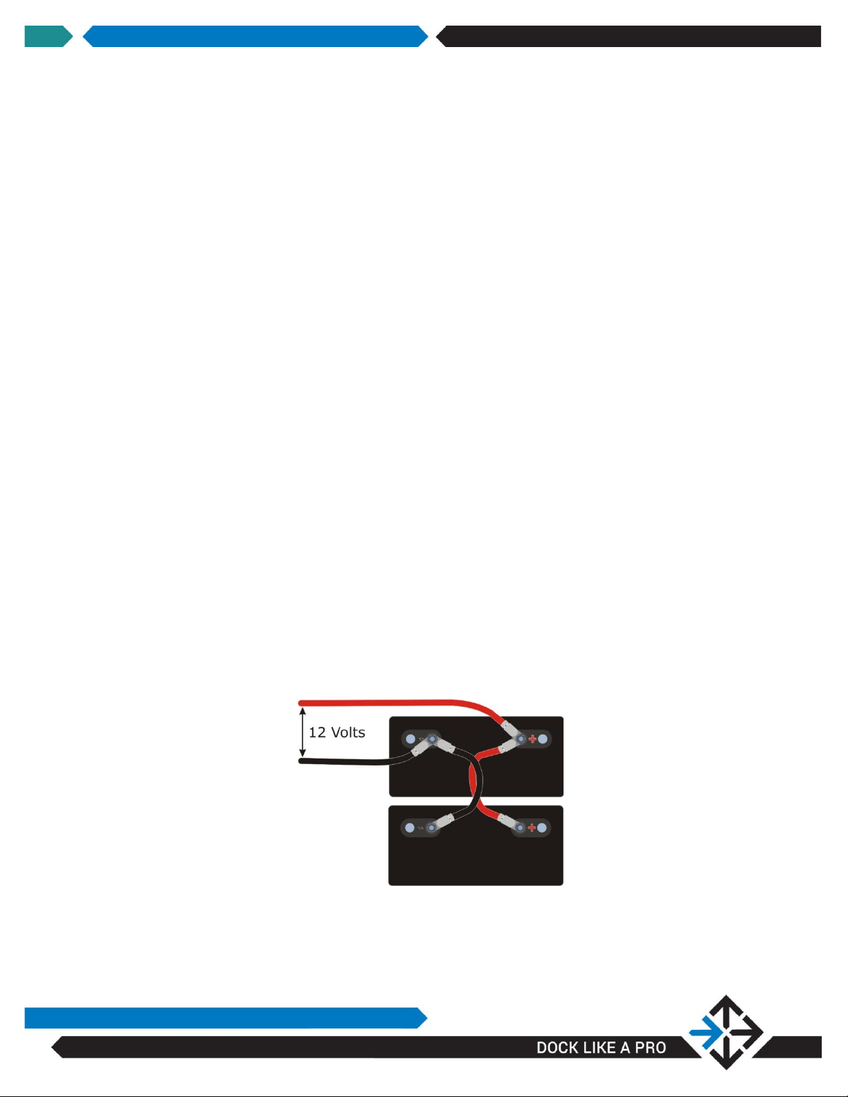
24 VOLT BATTERIES
24 volt batteries are less common than 12 volt batteries. You may find it more
convenient and less expensive to use two 12V batteries in series.
Figure 2: Two 12 V batteries in series, providing 24 V
To connect two batteries in series, connect the negative post of one battery to the
positive post of another using a short piece of battery cable of the same gauge used
to connect the batteries to the motor controller. The two remaining posts are each
connected to the motor controller using two battery cables, supplying 24V.
WINDLASS BATTERIES
It is possible to share an existing battery bank with a windlass, providing it has
sufficient capacity to meet both windlass and thruster usage, and is close enough to
the bow to supply the bow thruster. It is not recommended to power the stern
thruster from the windlass batteries due to the need for longer cable runs. Supplying
both bow and stern thrusters from a single battery is not recommended. The more
deeply discharged a battery becomes before it is recharged, the fewer charge cycles
it can provide in its lifetime, so if both thruster and windlass are used to a point

SIDESHIFT INSTALLATION GUIDE V2.7
15
where battery capacity drops below 75% before recharge, it is probably less
expensive to provide a separate battery bank dedicated to the thruster.
The cable gauge, CCA and circuit protection already in place for the windlass must
be compatible with the thruster in order for this approach to work. We do not
recommend using windlass batteries for our SS340 or SS350 bow
thrusters. See table below:
Thruster
Cable AWG
CCA
Circuit Protection
SS230
1/0
850 or greater
300 A peak
Table 1: Shared Battery Requirements
Cable and Terminal Requirements
Due to the high current load drawn by the motors, it is essential that the correct
type of cable and connectors are used, and that maximum cable length guidelines
are observed according to the gauge and thruster model. These guidelines are
summarized in the table below. The table assumes cables from the thruster to the
controller have not been shortened.
Cable must be high quality tin coated copper, marine grade cable. Cable ends must
be fitted with high grade cast copper, tin coated terminals and sealed with double
wall heat shrink tubing for moisture protection.
Recommended cable gauge for connecting motor controller to thruster battery bank,
fuse and battery switch:
Thruster Series
Cable AWG
230
1/0
340 & 230-Dual
2/0
240 & 350
2/0

SIDESHIFT INSTALLATION GUIDE V2.7
16
INSTALLATION OVERVIEW
Thruster installation involves three main phases: thruster mounting, joystick and
electrical installation.
There are differences between installing a bow thruster and a stern thruster,
although they share many common elements. Instructions for each type of
installation are covered separately below.
Electrical installation and joystick installation are similar for bow and stern thrusters.
Each is covered in a separate section.
Note that if you are installing both a bow and stern thruster, each thruster must
have a separate electrical installation, including batteries, motor controller and
joystick receiver. They can share a dual joystick which has two joysticks on a single
console, or use two separate single joysticks.

SIDESHIFT INSTALLATION GUIDE V2.7
17
INSTALLATION INSTRUCTIONS
–BOW THRUSTER
Bow thrusters can be installed with the boat in water or on land, although land-
based installation is easier.
In order to obtain the strongest possible epoxy bond(when not using through-bolt
hardware), installation should be performed when the hull is dry, clean and the
epoxy and hull surface temperature is between 70°F/21°C and 75°F/24°C .
View installation procedures on-line at Installation - Sideshift Bow Thrusters and
Stern Thrusters.
Bow Thruster Placement
The bow thruster is located on the center line, with the top of the propeller at least 5
inches (12 cm) below the shallowest waterline. The cables pass through the hull
above the waterline.
Figure 3: Bow Sideshift thruster placement

SIDESHIFT INSTALLATION GUIDE V2.7
18
Step-By-Step Instructions: Bow Thruster
STEP 1: DETERMINE WATERLINE
The propeller must be at least 5 inches (12 cm) below the shallowest
waterline and ideally out of the water when planing, so determining the
waterline is a crucial first step to installation.
Figure 4: Top of propeller 5" (12 cm) below water line

SIDESHIFT INSTALLATION GUIDE V2.7
19
NOTE: Be sure to determine the waterline with an empty boat to ensure
thruster placement will keep the propeller a minimum of 5” (12 cm)
below the waterline in the worst case scenario.
The water stain on the hull is a good indication of typical waterline over a
range of conditions. Use the lowest indication of waterline if a water
mark is visible.
If no water stain is visible, the waterline must be marked while the boat
is in the water. With the boat completely unloaded (fuel tanks empty but
standard equipment in place), mark the waterline near the bow of the
boat with a grease pencil.
STEP 2: POSITION CLAMP STRAP
Dry fit the clamp strap such that the holes at the end of each flange are between 2”
and 6” (5 and 15.25 cm) above the waterline. Mark the position on the bow with
tape. Duct tape works well.
Verify that drilling the hole locations selected in step a. above will not damage
anything on the inside of the boat, for example a water tank or wiring etc. If in
doubt, contact the boat manufacturer.
WARNING: Verify that the proposed location to drill the anchor holes and cable
holes as determined above will not interfere or damage anything on
the inside of the hull.
Remove the two-sided tape backing on clamp strap.
Reposition the clamp strap at the location marked above and fasten in place using
the attached two-sided tape.
This manual suits for next models
18
Table of contents
Other Sideshift Outboard Motor manuals

Popular Outboard Motor manuals by other brands

SLEIPNER MOTOR AS
SLEIPNER MOTOR AS Side-Power SH 700/ 412 TC Installation and user manual

Yamaha
Yamaha T9.9W Service manual

Torqeedo
Torqeedo Travel 401 S operating manual

Sleipner
Sleipner VECTOR FINS VF650 installation guide

Vetus
Vetus BOW3512F Installation and user manual

MotorGuide
MotorGuide R5 Series manual


