Sideshift PT230 PONTOON THRUSTER User manual

PT230 PONTOON
THRUSTER
(PATENT PENDING)
INSTALLATION/OPERATION
MANUAL
VOLUME 1.7, JULY 2016
Sideshift Inc. 130 Industrial Ave, Unit 303, Carleton Place, ON, Canada K7C 3T2
1.877.325.4787 +613.686.6011 INFO@SIDESHIFT.COM

SIDESHIFT INSTALLATION GUIDE V1.7
1
INTRODUCTION
Thank you for your purchase of a Sideshift thruster system.
Sideshift thrusters are designed for easy installation by anyone with basic mechanical
and electrical skills.
This manual explains everything you need to know about installing your Sideshift
thruster.
We also provide unlimited telephone support at
1.877.325.4787.
Also see our website for helpful installation videos at
sideshift.com/choose-sideshift/videos/videos/.
This manual explains the mounting and operation of the PT230 Pontoon Thruster
system. We recommend that you familiarize yourself with the complete manual
before starting your installation.

SIDESHIFT INSTALLATION GUIDE V1.7
2
Safety warnings
WARNING: To prevent overheating when operating the Sideshift
thruster, run for a maximum of 20-30 seconds at a time,
then allow to cool for at least 10 seconds before further
operation.
WARNING: Ensure main ignition is turned off and motor control breakers are
open when conducting maintenance and repair of the thruster.
WARNING: Use extreme caution when swimmers are in the area of the thruster.
Turn off ignition and avoid contact with thruster props when boat is
stationary.
WARNING: When operating out-of-water do not run thruster for longer than
5 seconds to prevent overheating.
WARNING: If conducting an in-water installation, use a cordless drill only, as a
corded drill can present an electrocution hazard.
Required Tools
Heat gun
3/8” drive cordless driver
3/8” hex socket
Wire stripper
Wire crimper
SAE wrench set 3/8” to 3/4”
Pliers
Drill bits up to ½”
Caulking gun
1 ¼” and 2 ½” hole saw

SIDESHIFT INSTALLATION GUIDE V1.7
3
Parts List
Item
Photo
Purpose
Thruster Kit
Single Joystick
Raise, lower and control
thruster.
Dual Wireless Joystick
Controls bow and stern thruster
from a single console for one-
hand operation.

SIDESHIFT INSTALLATION GUIDE V1.7
4
Wireless Control Module
Wireless receiver and control
interface between joystick and
motor controller.
Motor Controller
Relays commands from joystick,
delivering high current from
battery to motor.
Anti-seize
Prevents screw and bolt threads
from seizing, facilitating easier
assembly and disassembly.
Heat shrink tubes
(sufficient for all cables
attached to motor
controller. Cut to size)
Provides waterproofing for cable
at battery terminals.
SIDESHIFT INSTALLATION GUIDE V1.7
5
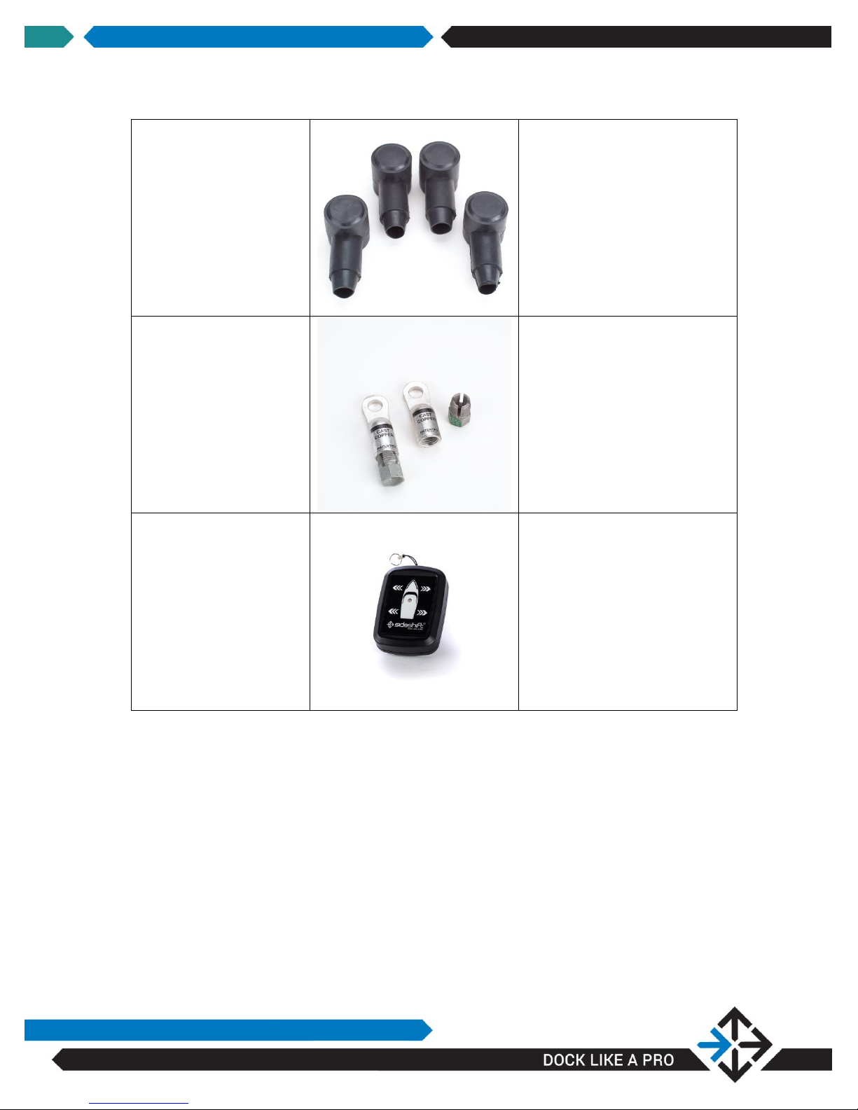
Terminal protectors
Protects terminals from moisture
and prevents shorts.
Compression terminals
Connects cables to motor
controller. Select size according
to wire gauge used.
Wireless Remote
Controls thruster remotely
SIDESHIFT INSTALLATION GUIDE V1.7
6
INSTALLATION INSTRUCTIONS
–PT230 PONTOON THRUSTER
Sideshift thrusters can be installed with the boat in water or on land, although land-
based installation is easier.
To get an overview of the installation process you can view the pontoon thruster
installation video on-line at sideshift.com/choose-sideshift/videos/videos/.
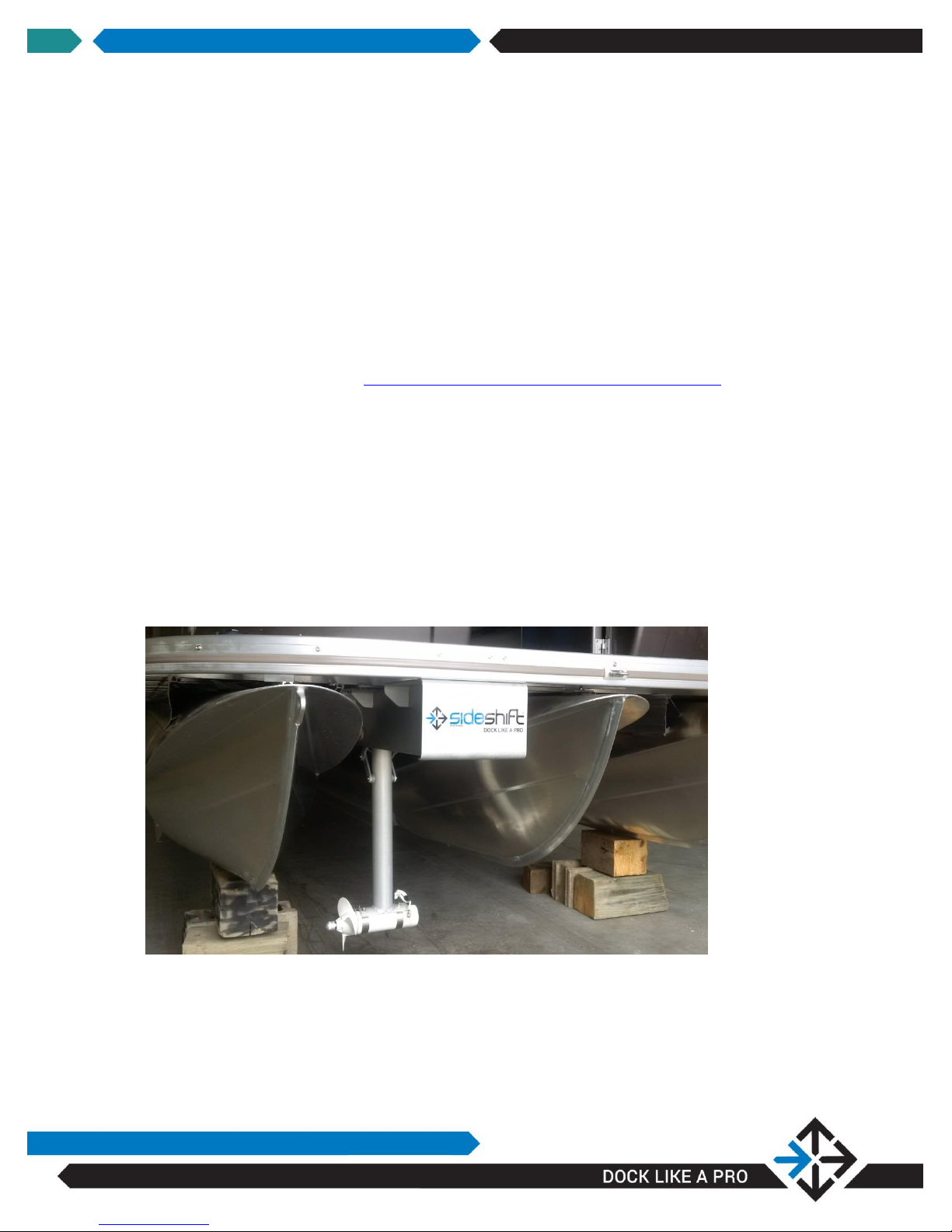
PT230 Thruster Placement
The thruster is designed to be positioned on the underside bow of any dual or tri-
pontoon boat. For tri-pontoon boats position the thruster between two pontoons on
the helm side of the boat which will facilitate wire-runs. For dual pontoons position
the unit centrally between pontoons.
The cables and air vent line pass through the deck and into storage typically found
under a hinged bench above deck.
SIDESHIFT INSTALLATION GUIDE V1.7
7
Step-By-Step Instructions:
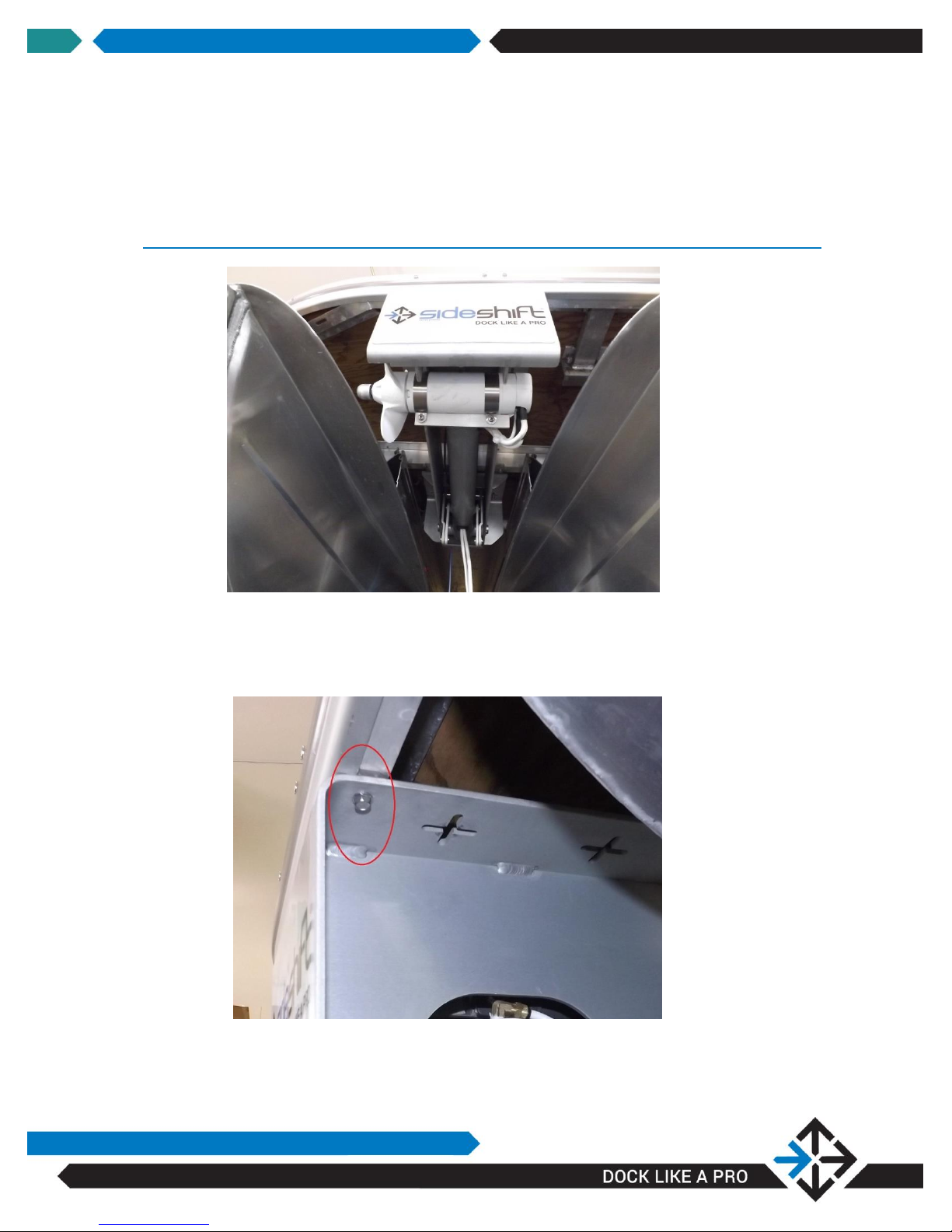
STEP 1: DETERMINE THE DISTANCE BETWEEN MOUNTING CROSS
MEMBERS
The unit has pre-drilled mounting slots to accommodate either 16” or 24”
centers. In some installations it will be necessary to drill the thruster
mounting plate as seen below, to fit centers other than 16” or 24” using a
¼” drill bit.
SIDESHIFT INSTALLATION GUIDE V1.7
8
NOTE: You will require a helper for Step 2
NOTE: The thruster should be positioned directly under the bow for best
performance. The thruster can be mounted further back on the boat
where it is less visible, but performance will be affected.
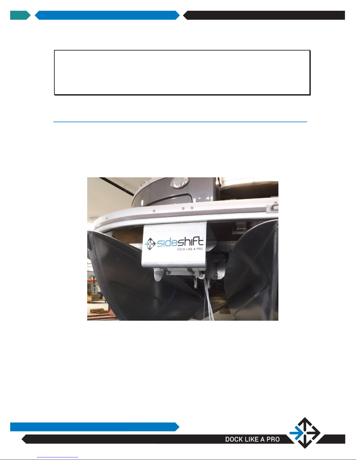
STEP 2: POSITION THRUSTER AND ATTACH TO UNDERSIDE OF
DECK
1. Using a helper, position the thruster in place, and using the supplied
self—drilling/self-tapping 1 ¼” stainless hex-head mounting screws, apply
a small amount of supplied Loctite to the threads and drive the screws
into the aluminum cross-members at the appropriate location. Pilot holes
are not required. Two screws are required at the front and two at the
back of the unit.
SIDESHIFT INSTALLATION GUIDE V1.7
9
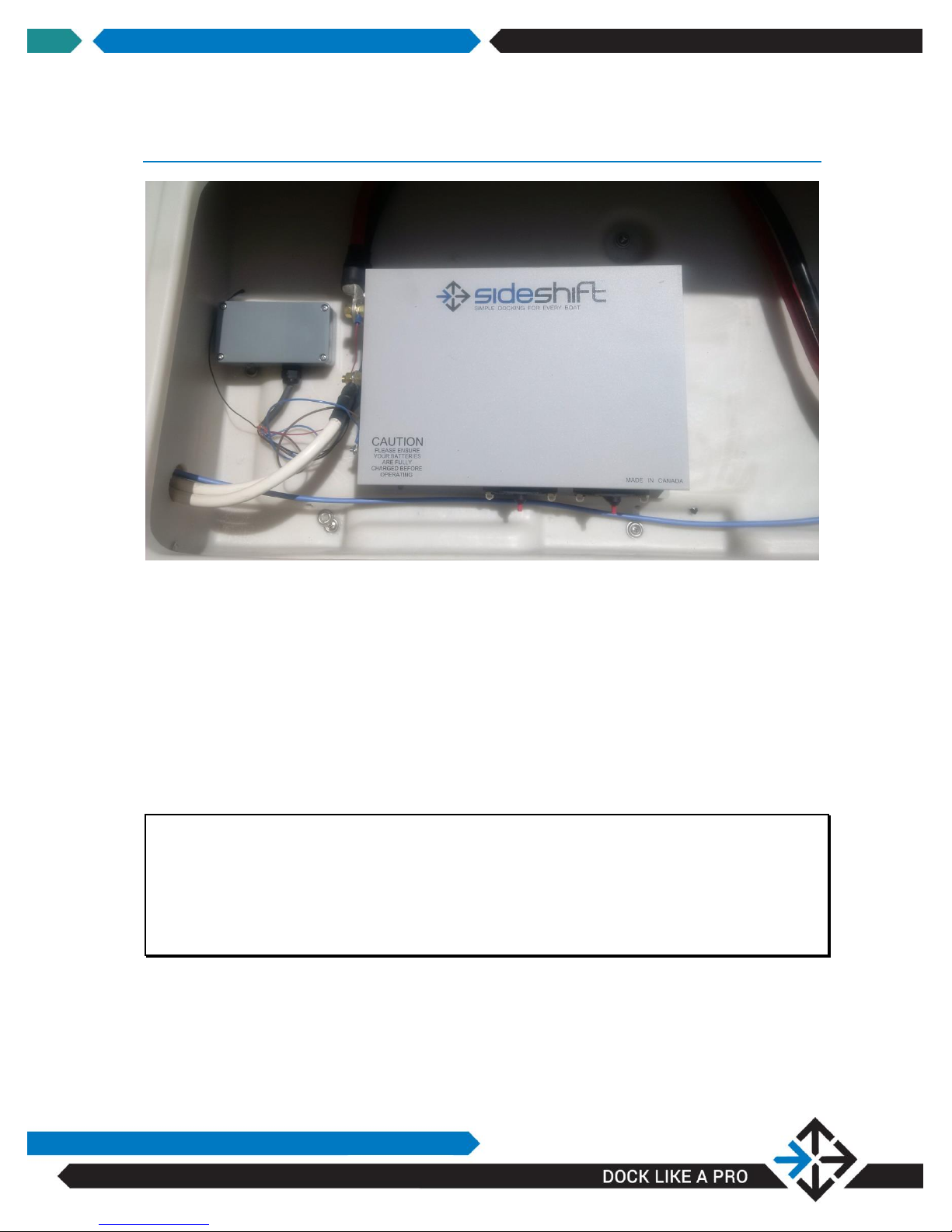
STEP 3: FEED WIRES AND AIR LINE THROUGH DECK
1. Determine a location for the motor control box, ideally in a dry storage
area close to the bow on the helm side of the boat.
2. Using a 1 ¼” hole saw, drill holes at appropriate locations for routing of
the thruster cables and air vent line.
Feed the thruster cables and air line into the storage location.
3. Route the motor control cables for connection to a dedicated 12v
starter-type battery.
4. Route a charge line from your house battery to the thruster battery.
WARNING: Verify that hole placement will not interfere with or damage
anything when drilling through the deck and storage location, and
that there is sufficient space so that cables can be accessed after
passing through the proposed hole location.
WARNING: Ensure the motor control box is located in a dry storage area

SIDESHIFT INSTALLATION GUIDE V1.7
10
NOTE: The air line prevents pressure buildup on the motor seals due to
temperature changes. The air line must not be crimped, and must
be positioned so that the open end is in a dry location

SIDESHIFT INSTALLATION GUIDE V1.7
11
INSTALLATION INSTRUCTIONS
–ELECTRICAL
Schematic –PT230

SIDESHIFT INSTALLATION GUIDE V1.7
12
Due to the high current draw, Sideshift thrusters must be supplied with a dedicated
starter-type battery for each thruster.
WARNING: High currents can result in reduced voltage supply to the thruster if
improper cable, connectors and/or assembly procedures are used.
This can result in poor performance or damage to the thruster
motor.
WARNING: Ensure the dedicated thruster battery is fully charged and load
tested. Low battery voltage can result in erratic actuator
performance(actuator arm will not extend or retract properly) and
poor thruster performance or damage to the thruster motor.
Correct cabling and connection practices are essential to maintaining correct
operating voltage. Batteries must be fully charged before use.
In most cases, the cable run from battery to controller is less than 10 feet, in which
case 1/0 AWG cable is appropriate. For longer runs, use 2/0 AWG cable. Heavier
cable can be used although it provides no performance advantage. If in doubt,
increase the cable gauge.
Batteries are usually in a very low part of the boat and subject to moisture or partial
submersion and very damp/corrosive conditions, therefore it is important that the
connection terminals are properly sealed to the cables using heat shrink tubing
(supplied).
Compression terminal sizes are labelled to match the following applications:
1&2 AWG Thruster cables
1/0 AWG Battery cable (motor controller end), SS230/PT230
2/0 AWG Battery cable (motor controller end), all other models
Ideally, the positive cables should be red and the negative cables black.

SIDESHIFT INSTALLATION GUIDE V1.7
13
NOTE: If in doubt of which cable gauge to use, call Sideshift for technical
advice.
Instructions:
STEP 1: CUT BATTERY CABLE TO LENGTH
1. Cut two lengths of marine battery cable of suitable length to reach from
batteries to controller. Note that one cable may need to be longer than
the other to accommodate the location of the battery terminals.
STEP 2: CONNECT BATTERY TO MOTOR CONTROLLER
1. Fit terminal protectors over each battery lead at the controller end.
2. Choose a compression terminal to match the cable gauge (typically 1/0
AWG for SS230 thrusters and 2/0 for all other models).
3. Install compression terminals. See How To Install Compression Terminals
on page 12 for instructions.
4. Attach positive cable to the “BATTERY POS” post on the motor controller.
Slip battery protector over terminal.
5. Repeat step b for “BATTERY NEG” cable.
STEP 3: CONNECT BATTERY
1. Fit battery protectors and then shrink tube over each battery lead at the
battery end.
2. Install compression terminals. See How To Install Compression Terminals
on page 12 for instructions.
3. Attach positive cable (connected to “BATTERY POS” post on motor
controller) to the positive post of the battery. Slip battery protector over
terminal.
4. Repeat steps b for “BATTERY NEG” cable.

SIDESHIFT INSTALLATION GUIDE V1.7
14
STEP 4: CONNECT THRUSTER TO MOTOR CONTROLLER
NOTE: Motor power cable polarity is not identified. If thrusters operate in
opposite direction from joystick, reverse cable connections on motor
controller.
1. If thruster power cables are too long, cut them to length. Be sure that
they are neatly routed, and comfortably reach the motor controller
terminals. Leave some slack to make installation easier.
2. Install compression terminals. See How To Install Compression Terminals
on page 12 for instructions.
3. Connect one cable to “MOTOR 1” and the other to “MOTOR 2”.
STEP 5: RESET CIRCUIT BREAKERS
Make sure both circuit breakers on the motor controller are reset by
rotating the yellow lever counter-clockwise into the body of the circuit
breaker.

SIDESHIFT INSTALLATION GUIDE V1.7
15
How To Install Compression Terminals
STEP 1: STRIP 1” (2.5 CM) OF INSULATION FROM EACH END OF
CABLES
NOTE: Take care when stripping insulation to avoid damaging conductor. If
some strands are removed the compression terminal will not make a
good connection possibly resulting in performance reduction, a fire
hazard or the cable pulling out of the compression terminal.
STEP 2: CHOOSE A COMPRESSION TERMINAL TO MATCH THE
CABLE GAUGE
STEP 3: LOOSEN COMPRESSION TERMINAL NUT
STEP 4: PASS EXPOSED CONDUCTOR THROUGH NUT
STEP 5: TIGHTEN NUT WITH WRENCH
You will feel the resistance increase a bit as you tighten the nut, then
become stiff, at which point the nut is sufficiently tight. Give the terminal
a tug to make sure it is solidly attached to the cable.
STEP 6: INSTALL HEAT SHRINK TUBE
1. Slide shrink tube up the cable so that it covers the shaft of the terminal
and the insulation of the cable.
2. Apply even heat to the shrink tube until it makes a solid seal around the
cable and terminal.
SIDESHIFT INSTALLATION GUIDE V1.7
16
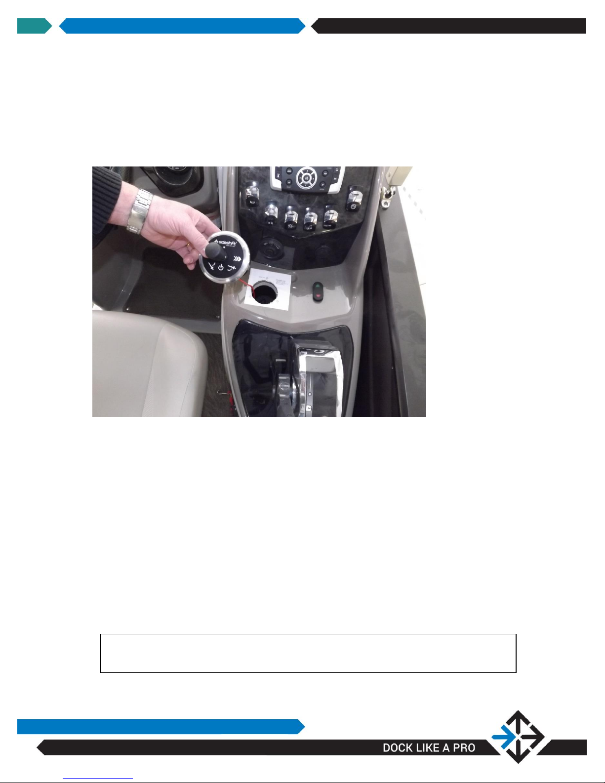
Installing Joystick on Console
1. Locate a position on the console of the boat suitable for the joystick.
Check under the selected position on the console to ensure a minimum
area of at least 4” diameter and a minimum three inches obstruction-free
below the area of the joystick equipment.
2. Peel the backing and place the supplied template in the chosen location.
3. Using a 3/16” bit, drill a hole at the center of the template, marked by the
cross-hairs.
4. Using a 2.5” hole saw and the pilot hole drilled in Step 3 above, drill a
hole at the center of the template.
5. Remove the template.
6. Connect the red and black leads from the joystick power cable to a direct
12v source under the helm.
Note: Do not connect the joystick cable through an accessory or other
type of switch.

SIDESHIFT INSTALLATION GUIDE V1.7
17
7. Plug the power cable into the back of the joystick
8. Run a thin bead of marine sealant in the groove around the underside
perimeter of the joystick, insert into the 2 ½” cutout and press in place.
Use a sharp knife or razor to trim any excess sealant.
CONNECTING WIRELESS JOYSTICK
AND ACTUATOR CONTROLS
Refer to PT230 schematic on page 11 for complete system layout
1. Position the control module in a dry location near the motor control box.
2. Connect the red and black leads from the 4 pin motor control cable to
“battery neg” and “battery pos” on the battery.
3. Connect “battery neg” and “battery pos” on the battery to “battery neg”
and “battery pos” on the motor control box.
4. Connect the blue and green leads from the 4 pin motor control cable to
“switch 1” and “switch 2” on the motor control box.
5. Plug the motor control cable into the black control module.
6. Plug the 6 pin actuator cable into the black control module.

SIDESHIFT INSTALLATION GUIDE V1.7
18
NOTE: The joystick and wireless key fob are preprogrammed for operation.
No pairing or programming is required.
OPERATING THE THRUSTER
WARNING: The thruster is equipped with an overload protection circuit. Should
the thruster encounter an obstruction when being retracted or
deployed, the unit will shut down a continuous alarm will sound.
You must turn power off and then power back on to the joystick,
which will reset the unit. Clear any obstruction under the boat and
proceed normally.
WARNING: Deploy and operate the thruster only when the boat is at slow speed
or stopped. Never deploy the thruster when the boat is at speed as
this may enable the overload protection circuit(see above warning)
or damage the unit.
WARNING: Ensure the area under the boat is clear when operating the thruster
and that there are no swimmers in the area.
1. Turn power on to the joystick by holding the power button for 1 second.
A beep will sound and the blue joystick light will activate.
2. To lower the thruster, press and release the down button on the joystick
console. A fast beep will sound during deployment, and a slow beep will
sound once the thruster is in the fully down position and ready for use.
3. Use the thruster in short bursts as required. Do not run for more than
20-30 seconds at a time.
4. To retract the thruster push the up button on the joystick console. A fast
beep will sound. When the unit is fully retracted the joystick will
automatically power off.
5. The joystick will automatically power-off after 5 minutes of non-use.

SIDESHIFT INSTALLATION GUIDE V1.7
19
WARNING Retract the thruster only when the boat is at slow speed or
completely stopped
OPERATING THE WIRELESS REMOTE
1. For operation of the wireless key fob the joystick must be turned on and
the thruster in the fully down position.
2. Push the top left or right buttons as required to operate the bow thruster.
3. Push the bottom left or right buttons to operate the stern thruster(if
applicable).
4. The wireless key fob will automatically power-off after 5 seconds to
preserve battery life.
5. A flashing green light indicates low battery. No green light indicates a
dead battery.
6. To replace the battery remove the 4 screws, open the case carefully, and
insert a new CR2032 coin cell battery.
OPERATION AND FAULT MODES
Operation
Action
Features
Power on thruster
Press and hold joystick
power button for 1
second
Short beep and solid blue
light to confirm power
Auto power-off after 5 min
of non-use
Lower thruster
Push and release
actuator down button
on joystick
Fast beep during
deployment
Slow beep when fully
extended
Operate thruster
Push joystick left or
right as required
Retract thruster
Push and release
actuator up button on
joystick
Fast beep when thruster
retracts
System will power-off
automatically once thruster
is fully retracted
Other manuals for PT230 PONTOON THRUSTER
1
Table of contents
Other Sideshift Outboard Motor manuals


