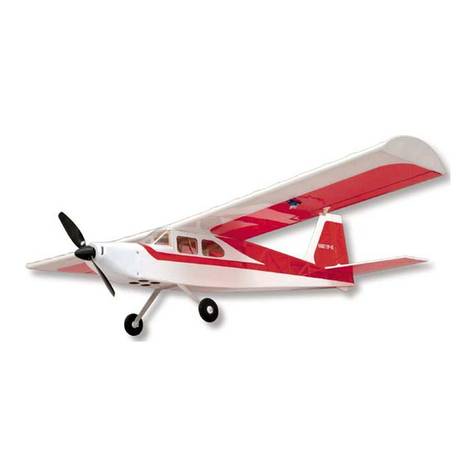
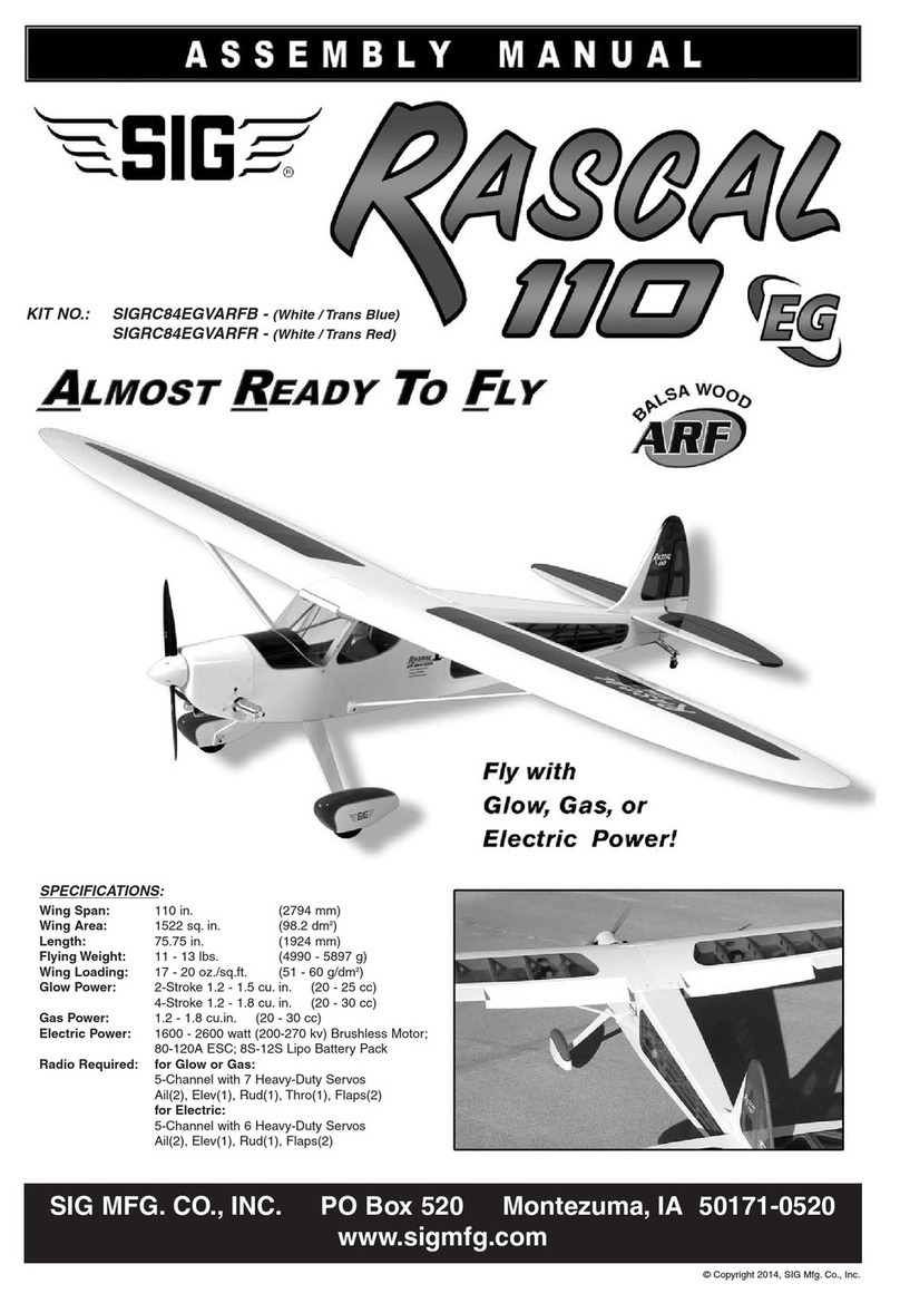
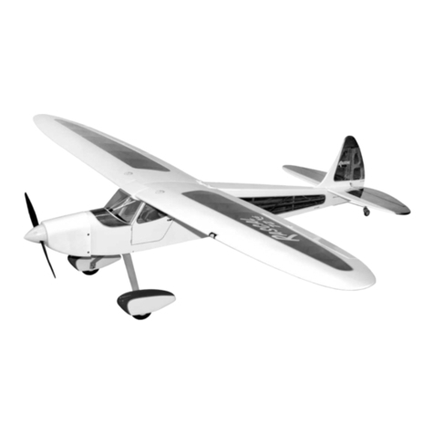
SIG Rascal 110 Technical manual

Rascal 110 MANUAL UPDATE
The kit you have is the latest version of the Rascal 110 ARF. It
includes several improvements over the previous release. This
MANUAL UPDATE will guide you through the changes that are not
covered in the ASSEMBLY MANUAL.
ASSEMBLY MANUAL Page 1 - Replace the four paragraphs
under RADIO EQUIPMENT with the following.
RADIO EQUIPMENT:
We highly recommend the use of a modern programmable
computer radio. Such radio systems allow you to easily set and
adjust every channel and additionally program various flight
functions to suit your individual style of flying.
The Rascal 110 ARF requires a 5-channel radio system, with 7
servos, assuming you are going to use the operational Flaps. If
you don't want working Flaps, you can get by with a 4-channel
radio with 5 servos.
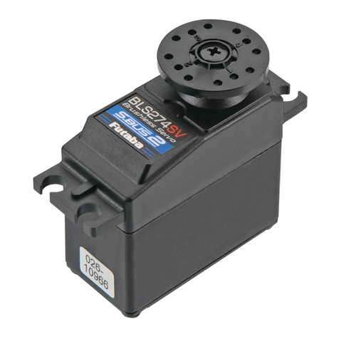
SERVO REQUIREMENTS
Ailerons - two (2) heavy-duty servos with at least 70 in/oz of torque
Flaps - two (2) heavy-duty servos with at least 70 in/oz of torque
Elevator - one (1) heavy-duty servo with at least 70 in/oz of torque
Rudder - one (1) heavy-duty servo with at least 70 in/oz of torque
Throttle - one (1) standard servo
SERVO CHORDS NEEDED
Ailerons - two (2) 24" long servo extension.chords
one (1) standard Y-harness chord (plugged into the rx)
Flaps - two (2) 6" long servo extension chords
one (1) reversingY-harness* chord (plugged into the rx)
Elevator - one (1) 36" long servo extension chord
Rudder & Throttle - no extra chords needed
* We used a Maxx Products®"Miracle-Y" Reversing Y-Harness.
No radio equipment is supplied in this kit. Heavy-duty servos,
extension chords of various lengths, and Y-harness chords are all
available separately from your radio manufacturer. Check their
website, or see your local hobby shop for more information.
RADIO Rx BATTERY PACK
Most radio systems, typically, come with a 500-600 mAh nicad
receiver battery pack, which runs the receiver and the normal 4
servos. Because the Rascal 110 carries as many as seven high-
torque servos, we strongly recommend that you upgrade to a
larger 1100-1500 mAh airborne battery pack in order to be safe.
All radio manufacturers have the larger capacity packs available
for their systems.
ASSEMBLY MANUAL Page 2 - Replace the entire section titled
COVERING MATERIAL with the following.
COVERING MATERIAL:
Your Rascal 110 ARF is covered with Oracover®, a premium quality
covering made in Germany, and sold in the U.S. by Hanger-9®as
Ultracote®.Colors
Oracover®#10 White (Ultracote®#HANU870) and
Oracover®#29Transparent Red (Ultracote®#HANU950)
or
Oracover®#59Transparent Blue (Ultracote®#HANU954)
If sometime in the future you need replacement covering or
matching paint for repairs, they are available from your local hobby
dealer or online from Hanger-9®.
How To Tighten Loose Covering
After you open your Rascal 110 and take all the covered parts out
of their plastic bags, the covering may begin to wrinkle. This is not
unusual and is no cause for alarm.
Your airplane was built and covered in a part of the world which
has relatively high humidity and therefore, the wood was likely
carrying a fair amount of moisture. When exposed to drier air, the
wood typically loses this moisture, dimensionally "shrinking" in the
process. In turn, this may cause some wrinkles. However,
wrinkles are easy to remove by just using a hobby type heat iron.
Caution: Trying to remove the wrinkles by hastily going over them
with a heat gun can lead to more problems. You should take your
time to carefully go over the entire model with a covering iron, as
we will describe.
We suggest using a model airplane covering iron for this process.
Cover the iron's shoe with a thin cotton cloth, such as an old t-shirt,
to prevent scratching the covering as you work.
After covering your iron, the next step is to set the iron to the
correct temperature. This is critical for achieving a good result!
The iron should be set to about 220°F - 250°F (104°C - 121°C) as
measured on the bottom of the iron using a thermometer.
If you do not have a thermometer, you can find the correct
temperature by trial and error. Set your iron to a medium setting.
Glide the iron over some of the covering that is over over solid
wood, such as the sheeted wing center section. Observe the
covering to see if any bubbles appear. If bubbles appear, the
covering is getting too hot! Turn down the temperature of the iron
and repeat the test.
If no bubbles appear, turn up the heat slightly and repeat the test.
Keep adjusting until you "zero in" on the correct temperature. Find
the temperature that will get the covering to stick down without
forming bubbles or causing the seams to pull away.
Once your iron is set to the correct temperature, go over the entire
framework of the airplane, making sure that the covering is
securely bonded to the structure everywhere the covering comes
in contact with the wood underneath. This takes some time, but is
worth the effort.
After you have all the covering secured onto the solid areas, turn
the temperature of the iron up to approximatelly 300°F - 320°F
(149°C - 160°C). This is the correct temperature for shrinking the
covering material.
Use the iron to tighten up any wrinkles in the "open" areas of the
model (no wood underneath the covering). Glide the iron over the
wrinkle for a few seconds, then remove. Repeat until the covering
is tight with no wrinkles.
If wrinkles keep coming back on the tail surfaces, you may need to
"ventilate" the areas between the ribs. Otherwise, the air that is
sealed in those relatively small areas will expand when the heat is
applied and actually cause the covering to stretch instead of
shrink. Use a pin to poke a tiny hole in the covering between each
rib, on the bottom of the part. That will let the expanding air
escape and the covering to shrink properly.
1
R
12/2011

Caution When Using Heat Guns: You can also use a hobby-type
heat gun to shrink the covering, but you must be careful around
seams or color joints. Getting too much heat on the seams may
cause them to "creep" or come loose. You must also be careful
when using a heat gun when working around the windshield and
side windows - heat will distort the clear plastic material.
Recommended Temperatures:
To adhere the covering - 220°F - 250°F (104°C - 121°C)
To shrink the covering - 300°F - 320°F (149°C - 160°C)
ASSEMBLY MANUAL Pages 3-4 - Replace the COMPLETE
KITS PART LIST with the following.
COMPLETE KIT PARTS LIST:
The following is a complete list of all parts contained in this kit.
Before beginning assembly, we suggest that you take the time to
inventory the parts in your kit, using the provided check-off boxes
(❑). note that the bolts and nuts required to mount your engine to
the motor mounts are not included in this kit and must be
purchased separately.
❑1 Bag (1) Right Wing Panel, covered
(1) Right Aileron, covered and hinged
(1) Right Flap, covered and hinged
❑1 Bag (1) Left Wing Panel, covered
(1) Left Aileron, covered and hinged
(1) Left Flap, covered and hinged
❑1 Bag (1) Fuselage, covered
(1) Molded Clear Plastic Windshield, with screws
❑1 Bag (1) Stabilizer & Elevator Assembly, covered and hinged
❑1 Bag (1) Fin & Rudder Assembly, covered and hinged
❑1 Bag (1) Fiberglass Cowling, painted white
(4) M3 x 10mm PWA Mounting Screws (taped inside
cowling)
❑1 Bag (1) Right Fiberglass Wheel Pant, painted red/white
(1) Left Fiberglass Wheel Pant, painted red/white
(2) M3 Blind Mounting Nuts installed in each wheel pant
❑1 Bag (1) Molded Clear Plastic Side Windows
❑1 Bag 3" Dia.White Spinner Assembly
❑ (1) Spinner Cone
❑ (1) Spinner Backplate
❑ (1) Prop Adapter Ring Set
❑ (4) M2 x 10mm Phillips Head Mounting Screws
❑1 Bag Engine Mount Assembly
❑ (1) Right Engine Mount
❑ (1) Left Engine Mount
❑ (4) M4 x 25mm PWA Mounting Bolts
❑ (4) M4 Flat Washers
❑ (4) M4 Split-Ring Lock Washers
❑ (4) M4 Blind Mounting Nuts
❑1 Bag Fuel Tank Assembly
❑ (1) 450cc (15.2 oz.) Fuel Tank
❑ (1) Fuel Tubing for inside fuel tank
❑ (1) Rubber Stopper (for glow engines only)
❑ (1) Front Clamp
❑ (1) Rear Clamp, threaded
❑ (1) M3 x 18mm Clamp Compression Bolt
❑ (3) AluminumTank Tubes - 40mm, 50mm, 60mm long
❑ (1) Metal Clunk Pick-Up Weight
❑ (1) 2-piece "Fuel Dot" assembly
❑1 Bag (1) Formed Aluminum Main Landing Gear, painted
white
❑1 Bag ❑ (2) 3-1/2" dia. (90mm) Main Wheels
❑ (2) M5 x 50mm Socket-Head Bolts for Axles
❑ (4) M5 Hex Nuts
❑ (2) M5 Split-Ring Lock Washers
❑ (2) M5 Plastic Spacer Sleeves
❑ (4) M4 x 20mm PWA Mounting Bolts for Landing Gear
❑ (4) M4 Split Ring Lock Washers
❑ (4) M3 x 12mm PWA bolts for Wheel Pants
❑ (4) M3 Split-Ring Lock Washers
❑1 Bag Tailwheel Assembly
❑ (1) Main Leaf-Spring, w/ Steering Arm & Tailwheel
❑ (1) Secondary Tailwheel Leaf-Spring
❑ (1) 3-Arm Rudder Steering Horn, Metal
❑ (2) M2 x 10mm PWA Mounting Screws for Rudder
Steering Horn
❑ (3) M3 x 15mm PWA Mounting Screws for Tailwheel
Assembly
❑ (2) Coil Steering Springs
❑1 Bag ❑ (1) Right Wing Strut, aluminum, painted white
❑ (1) Left Wing Strut, aluminum, painted white
❑ (4) M3 x 20mm Socket-Head Mounting Bolts
❑ (4) M3 Flat Washers
❑ (4) M3 Split-Ring Lock Washers
❑1 Bag ❑ (1) Aluminum Main Wing Joiner
❑ (1) Aluminum Tube Rear Wing Locator
❑1 Bag ❑ (4) Balsa Tail Fairings, covered
❑ (1) 5/16" x 3/4" x 5" Balsa Block for FuelTank Retainer
❑ (1) 1/8" plywood Fuel Tank Rear Former
❑1 Bag ❑ (1) Right Aileron Servo Hatch, covered
❑ (1) Left Aileron Servo Hatch, covered
❑ (1) Right Flap Servo Hatch, covered
❑ (1) Left Flap Servo Hatch, covered
❑ (8) 3/8" x 3/4"sq. Hardwood Servo Mounting Blocks
❑ (24) M2.6 x 8mm PWA Hatch Mounting Screws
❑ (2) 1/4-20 x 1-1/2" Nylon Wing Mounting Bolts
❑1 Bag ❑ (2) Plastic-coated Steel Pull-Pull Cables
❑ (7) Nylon Control Horns; ail(2),flaps(2),elev(1),rud(2)
❑ (1) Nylon Control Horn Base, for elevator
❑ (8) M3 x 12mm PWA Mounting Screws; for ail(4) &
flap(4) control horns
❑ (4) M2 x 20mm Mounting Bolts; for rud(2) & elev(2)
control horns
❑ (4) M2 Hex Nuts; for rudder & elevator control horns
❑ (4) Brass Pull-Pull Swage Tubes
❑ (4) Brass Pull-Pull Fittings w/ R/C Links and Hex Nuts
❑1 Bag ❑ (1) 5mm dia. x 19-3/4" Outer Throttle Pushrod Tube
❑ (2) 3mm dia. x 23-1/2" Inner Throttle Pushrod Tube
❑ (2) M2 x 22mm Threaded Studs with Metal R/C Links
❑ (5) 4-40 Pushrods, threaded both ends; ail(2), flap(2),
elev(1)
❑ (10) 4-40 R/C Links, for pushrods; ail(4), flap(4),
elev(2)
❑ (10) 4-40 nuts for pushrods; ail(4), flap(4), elev(2)
MISCELLANEOUS:
❑ (1) Printed Instrument Panel
❑ (1) Decal Sheet
ASSEMBLY MANUAL Pages 4-8 - Replace the entire section
titled WINGS with the following:
WINGS:
The Rascal 110 is designed with a permanent 2-piece wing
system, where the right and left wing panels will remain separate
for ease of transport and storage. You will join the right and left
wing panels at the flying field with the strong aluminum blade Main
Wing Joiner at the spar box location, and an aluminum Rear Wing
Joiner tube in the rear. This joiner system has proven itself to be
very tough and easy to use. This wing system is further
augmented in strength with the functional wing struts.
2

AILERON AND FLAP RADIO EQUIPMENT (see photo above)
AILERONS: Both aileron servos need a 24" extension chord in
order to exit at the center of the wing. A standardY-harness stays
plugged into the receiver for the ailerons. When the wing is put on
the airplane, the aileron extension chords are plugged into the
Y-harness.
FLAPS: Both aileron servos need a 6" extension chord in order to
exit at the center of the wing. A reversingY-harness stays plugged
into the receiver for the flaps. When the wing is put on the
airplane, the flap extension chords are plugged into theY-harness.
1) Attach the appropriate length extension chords onto the end of
each aileron and flap servo wire. Wrap each connection with a
piece of plastic tape, or heat-shrink tubing, to insure that it won't
come unplugged in flight. Also prepare the servos for mounting by
installing the rubber grommets and eyelets (supplied with your
radio system) in each servo.
2) Examine the wing panels closely. Inside the aileron and flap
servo bay openings you will see a short length of wood with a
string tied to it. These strings will be used to pull the aileron and
flap servo wires through the wing panel to the center of the wing.
Also note, on the bottom of each wing panel, at the center front
location, you will see an oblong opening. This is where the aileron
and flap servo wires will exit the wing panel. Inside this opening,
you will see another piece of wood with strings tied to it - this is the
other end of the strings in the aileron and flap servo bays. Leave
all of the wood pieces and strings in place for now while we mount
the aileron and flap servos to their hatches.
3) From the kit contents locate the following items:
(4) Aileron and Flap Servo Hatches
(8) 3/8" x 3/4"sq. Hardwood Servo Mounting Blocks
(8) M2.6 x 8mm PWA Mounting Screws
Notice that all four hatches are the same outer dimensions, and
thus, share the following common steps. However also notice that
there are right and left hatch covers, made to fit the right and left
wing panel hatch openings.
4) The aileron and flap servos will be mounted to the back
uncovered sides of their respective servo hatches.
a. First, position the servo on the backside of the hatch, with its
output arm directly over the center of the hatch's clearance slot.
Hold the servo tightly in position while you mark the correct
locations for two hardwood mounting blocks. Then set the servo
aside.
b. Use epoxy or slow CA glue to mount the 3/8" x 3/4" sq.
hardwood servo mounting blocks in correct position on the hatch.
Let the glue dry before proceeding.
c.Use eight M2.6 x 8mm PWA Mounting Screws to reinforce the
mounting of the blocks to the hatch. First use a ruler to find the
center of each block and mark it on the covered side of the hatch.
Drill a 1/16" dia. pilot hole at the mark - about 1/4" deep - through
the hatch and into the mounting block. Install a M2.6 x 8 mm PWA
Screw in the hole. Repeat for all the other mounting blocks on all
the hatches.
NOTE: ALL OFTHE PHOTOS ON PAGE 6 OFTHE ASSEMBLY
MANUAL ARE STILL APPLICABLE.
d. Finally, mount the aileron and flap servos in position on their
mounting blocks, using the servo mounting screws provided with
your radio system. To avoid possibly splitting the mounting blocks
with the screws, it's recommended that you first pre-drill pilot holes
in the wood with an under-size drill bit.
old photo 0020.tif
5) Pulling the aileron and flap servo wires through the wing.
a. Start with one of the aileron servos. In the aileron servo bay
opening, gently break loose the wood piece with the string tied to
it. Pull it and the string a few inches out of the aileron servo bay
opening. Remove the wood from the string and discard the wood.
Tie the end of the string securely to the end of the aileron servo
plug, as shown. It's best to tie the string on behind the plug, so
that it can't slip loose. Look at the closeup photo below - we
looped the string completely around the plug (fore and aft
direction), running the string between two of the wires at the back
of the plug. Do not pull the chord through the wing panel yet!
3

b. Repeat the previous step to tie the end of the flap retrievel
string to the flap servo plug.
c.Now break loose the wood piece in the oblong hole at the root
end of the wing panel to free the other ends of the aileron and flap
strings. Carefully begin pulling the strings and servo wires through
the wing panel towards the root end. Start with the flap string.
Lightly pull on the inboard end of the string while feeding the servo
chord into the hole inside of the servo bay. You may occasionally
feel like the wire has become stuck inside the wing. This is simply
the plug on the end of the servo wire hitting the side of the holes
in the wing ribs. Gently work the string back and forth from both
ends until the plug fits through the hole. Sometimes the servo plug
comes through all the ribs the first time without getting hung up,
and other times it seems like it gets hung up on every rib. Be
patient and don't try to force it. The holes in the ribs are large
enough to accommodate any common servo plug.
When the Flap servo plug becomes visible in the oblong hole,
reach in with a narrow needle nose pliers or a hemostat and grasp
the plug and pull it to the outside of the wing. Remove the string
from the plug and put an identification tag on the wire so you can
later identify this as the FLAP plug. Temporarily tape the plug to
the wing surface so they can't fall back inside the wing.
Once the flap plug is out of the hole, continue pulling the aileron
wire through the wing. Then repeat the entire process to pass the
aileron and flap servo wires through the other wing panel.
6) Mount the aileron and flap servos in their respective servo bays
in the wings, using the sixteen M2.6 x 8mm PWA Mounting Screws
provided (four screws per hatch).
a. Hold the servo/hatch in place and use a 5/64" dia. bit to drill a
hole in each corner of the servo hatch - through the hatch and
through the corner plywood mounting gussets that are built into
the wing. Be careful when doing this - do not run the drill bit
through the top of the wing!
b. Screw the hatches in place with the M2.6 x 8mm PWA
Mounting Screws.
7) At this point connect up your radio system so that you can
operate the aileron and flap servos in order to adjust their center
(neutral) position and overall travel.
a.Turn on the radio system and center the aileron trim lever on
the transmitter. Check to see if the aileron servo arms are both
perfectly centered on each servo - the arms need to be
perpendicular (90°) to the servo body when the servo is at neutral.
If necessary, take the servo arm off the servo and reposition to
make it perpendicular. If you are using a computer radio, you may
be able to easily center the two servos through the transmitter
menu. Note: If you have a double-sided servo arm, cut off the side
of the arm that you won't be using so that it cannot bind on the top
wing when the hatch/servo are installed in the wing.
b. While the radio is still on, determine if the servos are moving
the correct direction. Note that the aileron servos should be
moving in opposite directions to each other. If the direction of
travel is incorrect, reverse the action of the servos through the
transmitter. Doing this may re-center your servos a little. If so,
re-center the servo arms on the servos back to 90°.
c. Also check to see that the arm does not travel too far and hit
the ends of the slot in the hatch, or otherwise bind on the hatch in
any way.
d.Repeat this step to setup the flap servos - except with the flap
servos you are not concerned about a neutral position, only with
the overall travel volume. Look ahead to the section titled FLAP
HOOKUP to understand the full operation of the flaps.
*Note: Which channel to use for flaps? Some transmitters have a
toggle switch to activate the flap channel. These are typically two
or three position switches that give one or two pre-set flap angles
upon activation. While this works fine in many cases, we much
prefer to operate the flaps with a transmitter knob that allows us to
roll in as much or as little flap input as needed for the wind
conditions during any given flight. Check your radio manual to
figure out the best way to operate the flaps on your Rascal 110.
8) From the kit contents locate the following items:
(4) Nylon Control Horns
(8) M3 x 12 mm PWA Screws for mounting the control horns
(4) 4-40 x 4" Threaded Pushrods
(4) 4-40 R/C Links
(4) 4-40 Hex Nuts
AILERON HOOKUP
9) Use two pieces of tape to secure each end of the aileron to the
wing panel, holding it in neutral position.
10) Prepare the nylon control horns for mounting by first drilling out
the two holes in the base with a 3/32" dia. bit. This allows the
mounting screws to pass more freely.
a. Connect the R/C link on one end of the 4-40 pushrod into the
outermost hole of the aileron servo arm. (Note: If the clevis pin is
hard to snap into the hole in the servo arm, open up the hole in the
arm with a 1/16" dia. drill bit.)
b. Install a Nylon Control Horn on the other end of the 4-40
4

pushrod, clipping the R/C Link in the top or outermost hole in the
horn. (Again, if the clevis pin is hard to snap into the hole, open
up the hole with a 1/16" drill bit.)
c. Hold the control horn in place at the leading edge of the
aileron hinge line. Thread the R/C Links in or out to adjust the
overall length of the pushrod. With the servo in neutral and the
ailerons taped in neutral, the base of the control horn must rest flat
on the surface of the aileron with its front edge right at the hinge
line. Adjust the length of the pushrod until it is. Also, move the
control horn right or left as needed to position it parallel to the wing
ribs. Hold the horn in this position and use a pencil or sharp awl
to mark the two mounting hole locations for the control horn onto
the flap surface.
d. Rotate the pushrod out of the way and drill 3/64" dia. (or #56)
pilot holes - about 1/2" deep - into the aileron at the marks just
made. Be careful not to drill completely through the aileron!
e.Mount the control horn in place on the aileron using two M3 x
12 mm PWA Screws.
IMPORTANT: After mounting the control horns for the first time,
take them back off and put a few drops ofThin CA into each of the
screw holes in the aileron. The Thin CA will soak into the threads
in the wood, and when it dries, the holding power of the threads
will be much stronger. Use Thin CA only, not medium or thick CA.
Let the Thin CA dry completely before remounting the control
horns onto the ailerons.
11) Remove the tape holding the aileron in neutral position and
then turn the radio back on. Make sure the aileron trim lever is set
at neutral on the transmitter. Double check the movement of the
aileron both ways. If there is any binding, find the cause and
correct it now. Then, refer ahead in this manual to the section titled
CONTROL SURFACE TRAVEL to read the recommended travel
amount for the ailerons. Use the EPA (End Point Adjustment)
feature of your transmitter to yield the recommended amount of
aileron travel.
12) Repeat Steps 9, 10, and 11 for the second aileron.
SAFETY ISSUE:After centering the servos and setting the control
throws, "safety" each R/C clevis by slipping a short length of fuel
tubing (not supplied) over the clevis, as shown in many of the
photos. This will prevent the clevis from opening up and becoming
disconnected from either the control horns
FLAP HOOKUP
Unlike the ailerons, the flap servos both need to travel in the same
direction. The easiest and most convenient method to achieve
mirror image movement of the flap servos is by using a Reversing
Y-harness. Many radio manufacturers make them for their
systems. If your radio manufacturer does not make a reversing
Y-harness, another option is to purchase an aftermarket Reversing
Y-harness like the Maxx Products®"Miracle Y", which is what we
used.
13) Make sure your transmitter's flap control (knob or switch) is set
to the "flap up" position, and then, turn on the radio system. The
correct position for both flap servo arms when in the flap up
position is for the arms to be angled back towards the wing trailing
edge approximately 45°. Reposition your flap servo arms, as
necessary, to get them in this position.
When the transmitter is set to the "down flap" position, the servo
arms should both pull towards the wing leading edge. If your down
flap motion moves the servo arms towards the flaps instead of
towards the wing leading edge, then, you need to reverse the
direction of the flap channel in your transmitter.
Activate the transmitter flap control several times to make sure the
flap servo arms are in the correct position and the flap servos are
both traveling together in the right direction. If all is correct, put the
flaps servos in the full up position (servo arms 45°towards the
trailing edge) and turn the radio off.
14) a. Tape the flaps in the full up position.
b. Connect the R/C link on one end of the 4-40 pushrod into
the outermost hole of the flap servo arm.
c. Install a Nylon Control Horn on the other end of the 4-40
pushrod, clipping the R/C Link in the top or outermost hole in the
control horn.
d.Hold the control horn in place at the leading edge of the flap
hinge line. Thread the adjustable clevis in or out to allow the base
of the control horn to rest flat on the surface of the flap with its front
edge right at the hinge line. Move the control horn right or left as
needed to position it in line with the servo arm. Hold the horn in
this position and use a pencil or sharp awl to mark the mounting
hole locations for the control horn onto the flap surface.
e. Rotate the pushrod out of the way and drill 3/64" dia. (or
#56) pilot holes - about 1/2" deep - into the flap at the marks just
made. Be careful not to drill completely through the aileron!
f. Mount the control horn in place on the flap using two M3 x
12 mm PWA Screws.
15) Remove the tape holding the flap in full up position and then
turn the radio back on. Re-adjust the pushrod length if needed to
get the flap in full up position when the servo is full up. Then move
the flap switch or knob to the full down position. Full down position
should be approximately 1-3/4" down at the trailing edge,
measured at the root end of the flap. That equates to
approximately 30°down - which would be the maximum amount
you would ever want. Use the EPA (End Point Adjustment) feature
of your transmitter to yield the recommended amount of flap travel.
16) Repeat Steps 13, 14, and 15 for the second flap. When
finished, put the wing panels together on the wing joiners so that
you can see both flaps operating at the same time. Operating the
flaps from the transmitter, make sure both flaps are coming down
evenly and to the same position. If there is any unevenness or
binding, find the cause and correct it now.
5

With the exception of the decals, the wings are now complete and
ready to use. Set them aside for now.
ASSEMBLY MANUAL Page 15 - Section titled OPTIONAL:
The Du-Bro Kwik-Fill Fueling Valve (#334 for glow; #335 for gas)
shown in this section of the manual is still a great option for the
Rascal 110. However since Du-Bro now makes a Mount (#806) for
their fueling valve, we no longer put the SIG Fuel Valve Mounting
Bracket (#SIGSH759) in this kit.
In addition to Du-Bro, there are other brands and styles of fueling
accessories that have come on the market since the Rascal
Instruction Manual was first written.
FuelingValves: Fueling valves (like the Du-Bro Kwik-Fill) typically
have a one-way check-valve inside so that they can be installed in
the fuel line that runs from the fuel tank's clunk pickup directly to
the engine's carburetor. When you are re-fueling, the check-valve
keeps fuel from going forward into the carburetor and flooding the
engine. Fueling Valves are a deluxe option.
Fuel Dots: Another option that has grown in popularity is the "fuel
dot". A fuel dot is simply a plug (usually machined metal) that you
put in the end of a dedicated fuel line that you use to fill the tank.
The fuel dot normally includes a matching mounting collar that you
permanently install in the side of the fuselage or cowling.
1) A machined aluminum Fuel Dot is included with the fuel tank in
this kit!
a.To use the supplied Fuel Dot you will need to plumb a 3rd line
inside your fuel tank, in addition to the two lines shown on page
8-9 of the manual. Inside the tank, the new 3rd line should be bent
down to just reach (but not touch) the front bottom of the fuel tank.
This is the line that you will hook up to your fuel pump to fill and
empty the tank.
b. Figure out where you want to mount the fuel dot. Obviously,
it is a good idea to put it on the opposite side of the airplane from
your muffler. We have had good luck mounting the fuel dot in the
side of the fiberglass cowling. However, if you do that, be sure to
reinforce the cowling to keep it from cracking from the stress of
repeated plugging in and removing of the fuel dot. We cut a 2" dia.
piece of 1/8" thick scrap plywood and epoxied inside the cowling,
as shown. Then epoxy the fuel dot mounting collar in place.
NOTE: If you do not want to put the fuel dot in the cowling, you
can make a simple mount from 1/8" plywood that is glued and/or
screwed onto the front of the firewall. Then make an opening in
the cowling directly over the fuel dot, for access.
c. Install a length of fuel line tubing onto the new 3rd line exiting
the fuel tank. Poke the other end of that fuel tubing through the
fuel dot mounting collar, to the outside of the airplane. Then plug
the end of the fuel tubing with the fuel dot itself. Be sure to make
the fuel tubing long enough to reach at least 2" outside of the
airplane, so you will have enough tubing to hold onto while fueling.
d. After fueling, push the fuel tubing all the way back inside the
cowling, and the fuel dot into the mounting collar. It should fit
snugly so it won't come out in flight.
ASSEMBLY MANUAL Page 24 - Step 4)
Step 4) is not necessary. The elevators are already permanently
hinged to the Stabilizer in your Rascal 110.
ASSEMBLY MANUAL Pages 23-25
The top 2 hinges are already permanently glued into the Fin and
Rudder in your Rascal 110. You will glue the bottom hinge in when
you mount the Fin onto the Fuselage in Step 2 page 23. Steps 5,
6, and 7 on pages 24-25 can all be done after the Fin is glued onto
the Fuselage. Or you can perform some of those steps before
gluing on the Fin, if you prefer. It's your choice.
CONCLUSION: We apologize for the inconvenience of having to
deal with a separate Manual Update. The actual Assembly
Manual will be updated at the next printing. Enjoy your Rascal
110 ARF - it's one sweet flying machine!
6
Other manuals for Rascal 110
1
Other SIG Toy manuals

SIG
SIG RISER SIGRC52 Instruction Manual

SIG
SIG Rascal 110 User manual

SIG
SIG RASCAL FORTY User manual

SIG
SIG Edgetra ARF User manual

SIG
SIG KADET EP-42B User manual

SIG
SIG KADET EP-42 User manual

SIG
SIG 4-STAR 60 Instruction Manual

SIG
SIG SIGRC69 HOG BIPE User manual

SIG
SIG FOUR-STAR 40 ARF User manual

SIG
SIG RASCAL ARF User manual

SIG
SIG Sun Dancer User manual

SIG
SIG Sigrc47 Instruction Manual

SIG
SIG Tiger SIGFF22 Classic Series User manual

SIG
SIG FOUR-STAR 60 User manual

SIG
SIG WACO SRE SIGRC101ARF User manual

SIG
SIG SIGRC38 Instruction Manual

SIG
SIG SIGRC80 Rascal C User manual

SIG
SIG T-Clips 70 User manual

SIG
SIG RASCAL EP-49 User manual

SIG
SIG LIL' RASCAL User manual