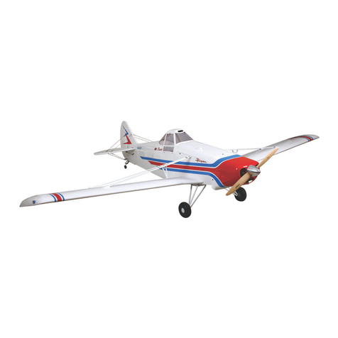
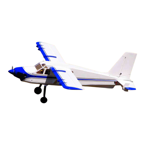
SIG WACO SRE SIGRC101ARF User manual


UC-72 light transport. Seven of these "drafted" Waco Aristocrats
survived the war and returned to civilian life. Today only four Model
E Aristocrats remain flying and are highly valued by their owners
and Waco enthusiasts alike.
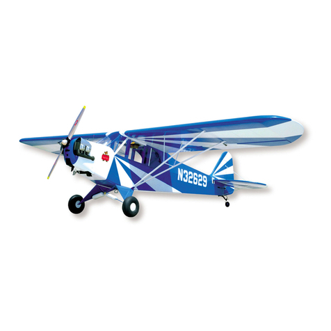
The SIG 1/6th scale Waco SRE ARF kit is a very nice tribute to the
exquisite lines and high-performance capabilities of its full-scale
counterpart. Based on the full-scale NC1252W SRE, the SIG
Waco shares its beautiful color scheme and undeniably Waco
lines. And in the air, the SIG Waco SRE is surely one of the nicest
flying scale R/C airplanes we've ever flown! The flaps are effective
and a lot of fun to work with. The flight controls are light, positive,
and smooth and the scale-like landing gear provides very good
take-off and landing performance.
The SIG Waco SRE ARF kit has been engineered to get you into
the air quickly with a model that you can be truly proud of on the
flight line. This Assembly Manual has been sequenced to put your
model together in the correct order. We urge you to read through
this manual carefully before starting assembly. We also urge you
to carefully check your kit contents against the included parts
listing in this manual, making sure that you have everything listed
before you start assembly.
Throughout this Assembly Manual we will reference the use of
various after-market products that were used in the assembly of
our own Waco SRE models. At the end of this manual you will find
a Product Reference section that provides you with contact
information for these various fine manufacturers.
Last, the SIGWaco SRE ARF model is NOT intended for beginning
R/C pilots. If this is your first R/C model aircraft, we strongly urge
you to seek the expertise and assistance required to both
properly assemble and fly this airplane.
Scale References:
SIG Manufacturing Company, Inc. wishes to gratefully
acknowledge the excellent reference materials listed below, used
in the development of this product:
◆"WACO AIRPLANES, Ask Any Pilot", Raymond H. Brandley,
Author
◆IMPS QUARTERY, Fall 1982, Published by International Plastic
Modelers Society
◆IMPS QUARTERLY, Winter 1982, Published by International
Plastic Modelers Society
◆BOB BANKA'S DOCUMENTATION SERVICE, "Foto-Pak"
#5283
Specifications: Imperial Metric
Wing Span, Top: 69.5 in. 1765.3 mm
Wing Area, Top*: 756 sq. in. 4877.4 cm2
Wing Span, Bottom: 48.3 in. 1226.8 mm
Wing Area, Bottom*: 354 sq. in. 2283.8 cm2
Wing Area, Total*: 1110 sq. in. 7161.2 cm2
Length: 56.5 in. (overall) 1435 mm
Flying Weight**: 9.5 - 10 lbs. 4.30 - 4.53 kg
Wing Loading: 19.7 - 20.7 oz./sq. ft. 60 - 63.3 g/dm2
Radio Required: 5 Channels (7 Servos required)
Engine Required: .75 - .90 2-Stroke
.90 - 1.20 4-Stroke
Scale: 1/6th
Kit Number: SIGRC101ARF
* Calculated at full span, including fuselage
** Flying weight can vary with use of different engines, battery packs, & equipment
R
1
Waco SRE ARF ASSEMBLY MANUAL
INTRODUCTION:
"Waco". There are just certain names that never fail to conjure up
the essence of the "Golden Age" of flight and the "Waco" name is
certainly one of them! The Weaver Aviation Company inTroy, Ohio
was synonymous with the art and grace of biplane design since
most of us can remember. And to this day, the Waco reputation
for designing and building some of the most elegant aircraft of
their time has endured. There has always been argument about
which specific Waco aircraft was the most beautiful, but virtually
everyone agrees that Waco aircraft in general were all beautiful in
their own way. And in our opinion, one of the most beautiful of all
Waco designs has to be the E series Aristocrat.
Prior to WWII, during the mid to late 1930's, a very real market had
developed for high-speed business and personal aircraft that could
carry a reasonable number of people and baggage. Walter Beech
had been refining his superb Staggerwing design since 1932 and
its evolution into the D17S model represented a great product for
this market. There were additional players as well, such as the
Howard DGA-15P, the Spartan 7W, the Lockheed Vega 5C, and
others. Waco, leaning heavily on their earlier "custom" C-8 cabin
biplane, rolled out their new E series prototype in October of 1939.
This aircraft, powered by a Pratt & Whitney Wasp Jr. 9-cylinder
radial engine, was quite fast and roomy. This 5-place cabin biplane
design was offered with four different engine options. Each engine
make was noted by Waco in their use of three-letter nomenclature
behind the name. These were:
Model E Aristocrat ARE = 330 hp Jacobs L-6mb 7-cylinder radial
Model E Aristocrat HRE = 300 hp Lycoming R680-E3 9-cylinder radial
Model E Aristocrat SRE = 450 hp Pratt & Whitney Wasp Jr. 9-cylinder radial
Model E Aristocrat WRE = 420 hp Wright R975-E3 9-cylinder radial
The most powerful version of this sleek new aircraft was the Waco
SRE, fitted with the 400+ hp Pratt & Whitney Wasp Jr. 9-cylinder
radial engine. In level flight the SRE was capable of better than
200mph and could cruise at just a little less than that! This was
very impressive performance for the time, especially considering
the design employed fixed, non-retractable landing gear.
Between October 1939 and February 1942, only 29 Aristocrat
Model E aircraft had been produced by Waco. Production was
ceased to fully devote the Waco factory to the war effort and the
production of their cargo gliders. Fifteen of the production
Aristocrat aircraft were called into service with USAAF, as the

ITEMS REQUIREDTO COMPLETETHIS KIT:
•Radio System, 5-channels, with seven (7) servos
•Appropriate servo extensions andY-harnesses (see Radio
Systems section below)
•After-Market Battery Pack - 1100 mah (optional, see Radio
Systems section below)
•Engine - See Engine Selection section below
•Propeller to suit engine of choice
•Engine Mounting Hardware:
4 each 8-32 x 1" Steel Socket Head bolts
4 each 8-32 Lock Nuts
4 each #8 Flat Washers
•Optional Fueling System - Du-Bro #334 Kwik-Fill Fueling Valve
shown in manual
•Optional Glow Driver system (as shown in this manual)
•1/4" thick foam rubber for installing receiver and battery pack
•Plastic Zip-Ties - used to organize and secure internal
components and wiring
•Thread Locking Compound - such as Loctite®#242
Non-permanent "Blue"
•30-Minute Epoxy - SIG 2-Part Epoxy Glue
•5-Minute Epoxy - SIG Kwik-Set Epoxy Glue
•CA Glue - SIG Thin, Thick, and SIG Accelerator
•White Glue, such as SIG Super Weld Liquid Resin Glue
•3/8" Dia. Heat Shrink Tubing to secure servo extension
connectors
•A selection of appropriate tools and materials, such as:
Electric Drill
Dremel®Tool with assorted bits
Safety Glasses
A selection of drill bits and/or a drill index set
Assorted sizes of both Phillips and regular screwdrivers
Assorted hex wrenches & ball drivers (2 mm and 9/64” required
for assembly)
Soldering Iron & solder - optional, used for Glow Driver system
connections
Hobby knife with #11 blades
Fine CA Applicator Tips
Scissors
Masking Tape
Scrap plywood sheet
Sandpaper - #220 is sufficient
RADIO SYSTEMS:
The SIG Waco SRE ARF model requires 5 channels to control the
ailerons, elevators, rudder, throttle and flaps, using a total of seven
(7) standard servos. Also, we chose to replace the typical 500 –
600maH airborne NiCad battery pack for a larger after-market
1100maH pack. We used this larger capacity pack in consideration
of the fact that it powers the receiver along with seven servos. We
suggest that you do the same thing with your own radio installation
in this model.
Many transmitters have toggle switches to activate the flap
channel. These are typically two or three position switches that
can input pre-set flap angles upon activation. While this works fine
we much prefer a rheostat type knob that allows us to roll in as
much or as little flap input as needed for the wind conditions
during any given flight. So we chose to use a Hitec Eclipse 7
QPCM transmitter that has this feature. In addition, this Hitec
transmitter also provides any number of mixing functions, as well
as exponential, end-point adjustments, sub-trims, etc. The use of
a computer radio system such as this saves a huge amount of time
and effort in the correct set-up and flight trimming of this or any
model.
As shown in this assembly manual, we chose to use an
aftermarket on/off switch assembly that provides the capability to
charge the airborne battery pack externally. The switch we chose
was the Maxx Products #3470 Charge/Switch product. This unit
has proven to be very reliable and very convenient in terms of
charging.
Another Maxx Products item that we chose to use in our ownWaco
models was the "Super Glow DLX" glow driver system, Maxx
Products P/N 9900DX. This system is programmable through your
radio system and keeps the glow plug lit at any pre-set throttle stick
location of your choosing. In addition, with this unit installed in the
Waco, there is no longer the need for a separate glow driver for
starting the engine. The Super Glow DLX system is quite light and
relatively easy to install. Based on our experience with this nifty
little system, we can highly recommend its use in your own Waco.
Of course, the use of this product is not a requirement and is only
offered as an option.
In addition to the above, you will also need the following items for
the radio installation:
2 each 6” Servo Extensions for aileron Y-Harness
2 each 12” Servo Extensions for the aileron servos
1 each 24” Servo Extension for the elevator servo
1 each Standard Y-Harness for the ailerons
1 each Servo ReversingY-Harness for the flap servos
(Maxx Products "MiracleY" or equivalent)
ENGINE SELECTION:
The SIGWaco SRE ARF model is designed to be powered by glow
engines in the following types and size ranges:
4-Stroke Engines: .90 - 1.20
2-Stroke Engines: .75 - .90
We prefer the use of 4-stroke engines for this particular model
simply because they sound great, allow the use of larger
propellers, typically use more manageable muffler sizes and are
very much in keeping with the model itself. However, this is
strictly our opinion and your own choice of engine type is up to you.
Carefully note that the SIGWaco SRE ARF model has a great deal
of wing area and therefore, a relatively light ready-to-fly wing
loading. This means that the airplane is not going to necessarily
fly "better" by being over-powered. We urge you to resist the
temptation to install larger engine sizes than those recommended
above. All this will accomplish is to make your installation more
difficult and potentially cause undue stress and strain on the
2

3
airframe. For reference, we performed all of our flight-testing with
our Waco models using .90, 1.00, and 1.20 4-stroke engines. The
.90 flies the airplane beautifully, as does the 1.00 engine. The 1.20
is close to over-powering the airplane but works fine with throttle
management. SIG's flying field is grass and all three of these
engines allowed easy take-offs.
This assembly manual depicts the installation of a Saito 1.00
4-stroke engine, mounted in the inverted position. This installation
has been completely tested and has demonstrated excellent
starting and running results along with great idle characteristics.
The Saito 1.00 engine provides the SIG Waco SRE with very good
power margins and excellent reliability. The installation of this
engine in our Waco will also show that the entire manifold and
muffler system can be kept within the confines of the cowl, with no
need for openings. Cooling airflow through the cowl and around
the engine has been completely tested on this design and found to
be excellent.
The only cowl openings required for this particular engine
installation were two small elliptical openings to clear the valve
boxes and a small diameter hole for the needle valve extension.
We really like this installation because it is practical and also
preserves the nice cowl and fuselage lines of the model. Take a
look at the Engine Installation section of this manual for more
complete details.
For reference, the practical maximum usable inside diameter of the
cowl is 7-1/2”. With the cowl fully in place on the fuselage, the
distance from the front face of the firewall to the rear face of the
spinner backplate is 5-7/16”.
Last, we strongly suggest that you take the time to carefully
break-in new engines. A good running, well broken-in engine
almost always minimizes engine related problems at the flying
field.
COVERING MATERIAL:
The SIG Waco SRE ARF model has been professionally covered
with SIG AeroKote®covering film. This high quality polyester film
has been expertly applied, using a scale color scheme, based on
the beautiful NC1252W full-scale Waco SRE.
The SIG Waco SRE ARF kits are built and covered in a part of the
world that is typically humid. When the individual covered parts are
removed from their plastic bags, some wrinkling may occur over a
24 to 48 hour period of time. This is especially possible if you live
in a drier climate. This phenomenon is perfectly normal and DOES
NOT mean that your model has a defect. Such wrinkles are a
result of the wood itself losing moisture and dimensionally
shrinking in the process. This is the nature of wood, especially
softer types, such as balsawood.
Some modelers may feel that the covering on the ARF model
should be perfect and that they should not be expected to re-shrink
wrinkles. This is not realistic, because any covering material -
regardless of brand - that has been hand applied over wood, is
indeed subject to the possibility of wrinkling.
The requirement is to therefore re-shrink the covering as needed.
This is not difficult to do and can be done using normal hobby-type
covering tools, such as a heat iron, a trim seal tool and a hobby-
type heat gun. Carefully note that we do not recommend the use
of a heat gun around any areas where two pieces of covering
material have been seamed together. This is because a heat gun
generates a great deal of broadcast type heat that in turn can
loosen seams, often causing the seams to "creep". If you must use
a heat gun around or near such seams, we suggest that you
protect them first. To do this, soak a few paper towels in cool tap
water and arrange the wet towels directly onto and over the
seamed area. You can then use your heat gun to carefully shrink
these areas.
When using a hobby-type heat iron, we always suggest that the
surface of the shoe be covered with a soft cloth. This helps
prevent scratching or hazing the surface of the covering material.
For years we have used old cotton T-shirt cloth for this purpose and
it has worked quite well for us. There are also commercially avail-
able "covering socks" that fit onto most covering iron shoes.
However, these can vary in quality, so choose one that feels the
softest. Also note that the temperatures required to shrink and
seal AeroKote®(275O- 325OF) are definitely high enough to melt
and/or distort some plastic parts. Exercise common sense when
working with high heat sources around the plastic parts on your
model!
For reference, the SIG Waco SRE ARF model was covered using
the following AeroKote®colors and part numbers:
Cub Yellow Opaque SIGSTL331
Black Opaque SIGSTL201
COMPLETE KIT PARTS LIST:
The following is a complete list of all parts contained in this kit.
Before beginning assembly, we suggest that you take the time to
inventory the parts in your kit, using the provided check-off boxes
(❑). Note that the CA type hinges for the ailerons, rudder, and
elevators are in place in each of these parts but are not yet glued
in place. Also note that the nuts and bolts required to mount your
engine to the motor mounts are not included in this kit and must be
purchased separately.
Important Note: Each Waco SRE ARF kit has been inspected
and inventoried on three separate occasions before leaving the
factory. Therefore, be assured that your kit has been checked
and was shipped with all of the listed parts included. Missing
part claims made after the assembly of the model begins
cannot be honored. Also, please be aware that the various
parts listed below may sometimes be packaged in a different
order than shown. Just be sure to check each parts bag to
make sure that you have received these parts.

4
❑Bag #1
Bottom Wing - Covered and trimmed with AeroKote®
•4-40 blind mounting nuts installed for N-struts -
2 on each side
•Wing bolt holes drilled and opened
•Wing bolt reinforcement plates installed and covered
•Rigging mount screw holes established
•N-strut mounting bracket recesses holes established
❑Bag #2
Vertical Fin & Rudder Assembly - Covered with AeroKote
®
•With four (4) CA hinges in place, not glued
•Bottom LE of rudder slotted and drilled for tailwheel
wire
❑Bag #3
Horizontal Stabilizer & Elevators - Covered with AeroKote
®
•Six (6) CA hinges in place, not glued
•Covering removed at center of stabilizer for gluing
❑Bag #4
Top Left Wing Panel - Covered & trimmed with AeroKote
®
•Flap assembly hinged with four (4) point hinges -
not glued
•Aileron hinged with four (4) CA hinges, not glued
•
Outer N-strut mounting recesses established with
4-40 blind mounting nuts installed for N-strut brackets
•Rigging mount screw holes established
•Aileron & Flap servo mounting openings made with
servo cable strings in place
•8mm dia. rear locating dowel in place & glued
•8-32 blind nuts installed in wing root rib for wing
mounting
❑Bag #5
Top Right Wing Panel - (same description as above)
❑Bag #6
Fuselage - Covered with AeroKote®
•Removable Top Hatch in place with
two T2.6 x 8 mm PWA mounting screws
•Front Windshield, painted - in place with
four T2.6 x 8 mm PWA mounting screws
•Main Landing Gear Hatch in place with
two T2.6 x 12 mm PWA mounting screws
•Landing gear 8-32 blind mounting nuts (4) in place
•
Firewall centering lines for engine mounting reference
•
Bottom rear hardpoint for mounting tailwheel assembly
•Fitting slots & 4-40 blind mount nuts (2) in place for
rear landing gear supports
•
1/4-20 Blind Nuts (2) installed for bottom wing mounting
•Pull-pull exit slots cleared out at rear of fuselage
•Firewall and air dump opening fuel-proofed
❑Bag #7 Cowl, fiberglass, & factory painted and trimmed, with
four (4) pre-drilled mounting holes
❑Sub bag A: (taped to inside of cowl):
4 each T2.6 x 8 mm PWA mounting screws
❑Bag #8 Main Landing Gear - 3 mm aluminum
• Factory painted yellow
•Pre-drilled with all required strut, axle and wheel
pant mounting holes
❑Bag #9 1 each Wheel Axle Wire - 4 mm dia. pre-bent to
shape, painted yellow
❑Sub bag A:
1 each Center Landing Gear Wire Mounting
Block - Nylon
1 each Nylon Strap - Main landing gear wire
retainer for nylon block
2 each Nylon 4mm Main Landing Gear Wire
Axle Bushings
❑Sub bag B:
4 each T2.6 x 10 mm PWA Screws, nylon block
mounting screws
❑Bag #10 2 each
Main Wheels - 70 mm dia. (2-3/4”), "Lite" type
❑Sub bag A:
4 each Wheel Collars, 4 mm ID, with setscrews
4 each 4-40 x 9 mm Allen Head bolts - wheel
pant mounting
4 each 8-32 x 14 mm Allen Head bolts - main
landing gear mounting
4 each 3 mm Flat Washers - 4 each for wheel
pant mounting
4 each 3 mm Split Ring Lock Washers - 4 each
for wheel pant mounting
4 each 4 mm Flat Washers for main landing
gear bolts
4 each 4 mm Split Ring Washers for landing
gear bolts
❑Bag #11 2 each Wheel Pants, plastic, factory painted
•With 4-40 blind mounting nuts installed (2 per pant)
❑Bag #12 2 each N-Struts, factory painted & pre-drilled
❑Sub bag A:
Rear Landing Strut Supports - 2 mm aluminum
•
Factory painted yellow
•
Mounting holes drilled
❑Sub bag B:
4 each 4-40 x 9 mm Allen Head mounting bolts
2 each 4-40 Lock Nuts
2 each 4-40 Flat Washers
❑Sub bag C:
8 each N-Strut Mount Brackets, aluminum,
factory painted, pre-drilled and bent -
4 each Top wing brackets,
4 each Bottom wing brackets
❑Sub bag D:
16 each 4-40 x 9 mm bolts with 2 mm Allen drive
heads - "N" strut mounting
8 each 4-40 Lock Nuts for above bolts - N-strut
mounting
❑Bag #13 2 each Molded Clear Plastic Side Window Set -
2 left & 2 right windows
❑Bag #14 1 each Top Wing Joiner Blade - 3 mm aluminum,
pre-drilled for mounting
❑Sub bag A:
2 each 4-40 x 10 mm Allen head bolts -
wing blade mounting
2 each 4-40 Lock Nuts
2 each 4-40 Flat Washers
❑Bag #15 1 each Fuel Tank Assembly, 450 cc (15.2 oz.) nylon
tank body with clunk fuel line inside
❑Sub bag A:
1 each Rubber Stopper
3 each Aluminum tank lines

5
1 each Front Clamp
1 each Rear Clamp, threaded
1 each M3 x 20mm Clamp Compression Bolt
1 each Fuel Pick-Up Weight
❑Bag #16 1 each Waco Spinner Assembly – Cone &
Backplate, Aluminum, 2-1/4" dia.
❑Sub bag A:
1 each Brass Union Nut - M8 x 1.25 mm x 8-32
1 each Spinner Mounting Bolt - 8-32 x 9/16"
❑Bag #17 1 each Fuel Tank Retainer - Balsawood,
9 mm x 12 mm x 90 mm
1 each Rudder Servo Mounting Doubler - Lite-Ply,
3 mm x 40 mm x 70 mm
2 each Throttle Tube Mounts - Lite-Ply, 3 mm
❑Sub bag A:
2 each Nylon Wing Bolts, 1/4-20 x 1-1/2",
slotted - Bottom Wing Bolts
2 each 8-32 x 25 mm Allen Head Top Wing
Retaining Bolts
2 each 8-32 (4 mm) Flat Washers for top wing
retaining bolts
2 each 8-32 (4 mm) Split Ring Lock Washers for
top wing retaining bolts
❑Bag #18 Reinforced Nylon Motor Mounts, 1 left, 1 right -
.90 to 1.20 size
❑Sub bag A:
4 each 8-32 x 25 mm Motor Mount Bolts
4 each 8-32 Blind Mounting Nuts
4 each 4 mm Flat Washers
4 each 4 mm Split Ring Washers
❑Bag #19 1 each Tailwheel Assembly - assembled with
25 mm dia. tailwheel and two 2.1 mm ID
wheel collars
❑Sub bag A:
3 each T2.6 x 10 mm Phillips Head Mounting
Screws
❑Bag #20 1 each Outer Nylon Throttle Pushrod Tube - 15-1/2"
1 each Inner Nylon Throttle Pushrod Tube - 15-1/2"
1 each M2 x 295 Steel Pushrod, threaded one end
with metal clevis
1 each Solder Clevis, M2
1 each M2 x 22 mm Threaded Stud
1 each M2 Threaded Metal Clevis
2 each Aileron Pushrods, M2, threaded at one end
w/ "Z" bend 2-7/8" (73 mm)
2 each Flap Pushrods, M2, threaded at one end
w/ "Z" bend 2-1/2" (63.5 mm)
1 each Elevator Pushrod, M2, threaded at one end
w/ "Z" bend 3-3/8" (85.7 mm)
❑Bag #21 Rudder Pull-Pull Cable - Nylon-coated -
Two (2) 39-3/4" lengths
❑Sub bag A:
4 each Threaded Rigging Couplers with Steel
Clevises
4 each 3 mm x 4 mm Copper Swage Tubes
❑Sub bag B:
7 each Nylon Control Horns
1 each Nylon Control Horn Bases
❑Sub bag C:
4 each M2 x 15 mm Phillips Head bolts - rudder
& elevator control horns
8 each T2.6 x 12 mm PWA Screws - flap &
aileron control horns
2 each Hex Nuts - rudder control horns
❑Bag #22 8 each Wing Flying Wires - 0.6 mm dia. x 13-3/4"
❑Sub Bag A:
8 each M2 Flying Wire Turnbuckles w/Locknuts
in place - Left-hand threads
❑Sub Bag B:
8 each M2 Flying Wire Turnbuckles w/Locknuts
in place - Right-hand threads
❑Sub Bag C:
16 each
T2.6 x 8 mm PWA Mounting Screws
16 each
Flying Wire Swage Tubes, 3 x 4 mm
2 each
Flying Wire Separators, Pre-Drilled, Nylon
❑1 each Waco SRE ARF Assembly Manual
❑1 set Waco SRE ARF Decal Sheets
Incidence & Thrust Angle Information:
Incidence and thrust have been built into this model at the factory.
However, some modelers may still wish to know these values:
Incidence: Top Wing -1O
Bottom Wing 0O
Horizontal Stabilizer 0O
Engine Thrust: Right Thrust: 2O
Down Thrust: 2O
Hardware 101:
Every modeler has heard stories about "inferior" foreign
hardware - we certainly have. While some of this might be
deserved, the fact of the matter is that much of this comes from
folks who failed to use the right tools for the job. A case in point
is the common Phillips screwdriver. These things come with
bits in all shapes, sizes, and angles. If you use a Phillips
screwdriver that has too small of a bit for the screw, it will almost
always "roach" out the head under the pressure of installing or
removing it. And the same is true if the screwdriver bit is too
large. One size does not fit all! Slotted screws installed with
under or oversized screwdrivers can also suffer from this same
kind of abuse. From experience, we can also tell you that
magnetized screwdrivers are great for this project. Having the
right tools available for the job can make a big difference in
making the job all that much easier and enjoyable.

Top Wing Panels:
As received in the kit, both of the top wing panels have the ailerons
and flaps in place with the appropriate hinges. Note that these
hinges are NOTglued in place. In the following steps, you will be
required to test the movement of the aileron and flap servos with
your radio system. So now is a good time to place both the
airborne battery pack and the transmitter on charge in order to use
them later.
❑1) The flaps are hinged first. Begin by removing the flap and
its four point hinges and the aileron and its CA hinges from both of
the wing panels. Set the ailerons aside for now.
❑2) Use a toothpick or sharpened dowel to apply a small
amount of Vasoline®to the center pivot point of each point hinge,
making sure this area is well coated - do not get Vasoline®on the
outer hinge arms. The Vasoline®helps to protect the hinge pivot
point from epoxy glue. Using 30-minute epoxy, glue all four hinges
in place into the pre-drilled holes in the flap.
Each exposed hinge leg should be oriented 90Oto the flap. Use
alcohol and a paper towel to carefully remove any excess or
oozing glue from the center hinge point and let the glue cure.
Repeat this process with the opposite wing panel and its flap.
❑3) The flaps are now mounted in place to their appropriate
wing panels. Trial fit the flaps first to make sure that they line-up
with the top and bottom surfaces of the wing panel. Make
adjustments as needed in the mounting holes to achieve a good fit.
Again using 30-minute epoxy, apply glue in the hinge holes and to
the exposed flap hinge legs. Press the four hinge legs into the
holes in the wing panel. Use a piece of tape on the top of the panel
to hoId the flap in place. A little alcohol and a paper towel will
remove any excess or oozing glue from the hinge points. Repeat
this procedure with the remaining flap on the opposite wing panel.
Allow the glue to cure.
ASSEMBLY:
WINGS:
Bottom Wing:
The bottom wing has been completely built and covered at the
factory with no further structural steps required. However, in
preparation for final assembly later, now is an excellent time to
prepare the bottom wings for assembly to the airframe.
❑1) From the kit contents locate Bag #12 containing the
N-struts and related strut hardware items. Open the small bag
containing the eight (8) pre-painted N-strut mounting brackets. The
bottom wing N-strut brackets have been pre-bent with open angles
- select these four brackets for this step (the four remaining
painted N-strut mounts, with the pre-bent closed angles, will be
installed into the top wing panels shortly).
From the remaining small bag, select four of the 4-40 x 13 mm
bracket mounting bolts. Use a 2 mm Allen head hex wrench to now
install the four N-strut brackets in place into the recesses in the top
of the wing. We suggest using thread locking compound on the
bolt threads and tightening the bolts firmly.
❑2) The top surface of bottom wing has four (4) small holes on
each wing panel. These have been opened at the factory to
identify their locations. These holes are the screw locations for the
rigging brackets, used to anchor the flying wires. Beneath these
holes are hardwood mounting blocks. Because the bottom wing is
easy to work with at this point, we suggest pre-threading these
holes now, in preparation for installing the rigging brackets later. To
do this, locate Bag #22 and remove one of the T2.6 x 8 mm PWA
Mounting Screws. Use a Phillips screwdriver to thread this screw
fully into each of the eight holes, pre-threading them. Set the
bottom wing aside for later final assembly in this manual.
6

Remove the tape holding the aileron in the downward flexed
position. Flex the aileron in the opposite, upward position and use
a piece of masking tape to hold it in place. Turn the wing panel
over and repeat the above gluing process - four drops of glue
to each side of the hinge slot - on all four hinges. Remove the
masking tape, returning the aileron to its centered position.
Because it takes some time for the CA glue to fully "wick" its way
through the hinge surface and the surrounding wood, allow about
10 minutes before flexing the aileron. Any excess glue on the
surrounding covering can be quickly removed with SIG Debonder.
After sufficient time has passed, flex the hinged aileron firmly up
and down on the panel to create free and easy movement. We
also suggest pulling on each aileron, at each hinge location,
making sure they are each firmly in place. Repeat this same
procedure with the opposite wing panel and aileron.
❑5) The aileron servos are now installed in each wing panel.
Note that these two servos will be oriented in the wing panels with
their output arms facing outwards towards the wingtips, with the
head of the servo toward the leading edge.
Prepare the two aileron servos by installing a 12” servo extension
onto each servo connector. We suggest that you make these
connections secure by using a short length of heat shrink tubing,
shrunk around the servo and extension connections. Now install
the rubber grommets and eyelets that came with your servos into
the servo mounting lugs.
Using the string found in the aileron servo opening, tie it to the
servo extension lead. At the root rib, pull the servo extension
through the wing panel and out through the opening. Use a piece
of tape to hold the connector against the root rib. The servo can
now be seated into the servo opening in the wing panel. Use a pin
vise and a small diameter drill bit to make four screw "pilot" holes
through the hardwood mounts. Using the screws that came with
7
After the epoxy cures, flex each flap to free up their movement. We
used a small amount of gun oil on the hinge points to further free
up their movement.
❑4) The ailerons are now hinged in place to each wing panel.
The supplied hinges are the CA type. Note that the installation
procedure for these hinges is the same for the elevators and
rudders and will not be repeated in those related steps.
The supplied hinges have a die-cut center slot that can be used to
accurately place and center the hinges equally into both the wing
panel and the aileron. To do this, use a business card and pair of
scissors to cut four "wedges". These should be cut wide enough at
the top so as to not pass through the slot in the center of the hinge.
Press the hinges into place into the pre-cut slots in the wing panel,
up to the center slot. Place a card "wedge" into each of the hinge
slots.
Now fit the aileron carefully onto each exposed hinge half, up to the
card wedges. Align the outer tip of the aileron with the wing tip, by
sliding the aileron left or right as needed. Next, make sure that
when the aileron is in its correct position, there is a reasonable
clearance between the inboard end of the aileron and the outboard
end of the flap. We used a business card as the spacer between
these two surfaces. With everything checked, the hinges can now
be permanently glued in place using thin CA, preferably with a
small applicator tip on the bottle.
Flex the aileron downward, exposing both sides of the hinges,
between the wing panel and the aileron. Use a piece of masking
tape to hold the aileron in this position. Remove the card "wedge"
from one of the hinges and apply four (4) small drops of glue to
each side of the hinge slot. Remove the card "wedge" from the
next hinge and again apply four (4) small drops of glue to each side
of the hinge slot. Repeat this process with the remaining hinges.

Pushrods (2-1/2" long with a metal clevis at one end and a Z-bend
at the other). Locate Bag #21 and remove four (4) Nylon Control
Horns and the eight (8) T2.6 x 12 mm PWA screws.
The flap linkages are installed first. Select the two 2-1/2” flap
pushrods, two nylon control horns, two nylon control horn bases,
and four M2 x 20 mm Phillips Head bolts.
The easiest and most convenient method to achieve mirror image
movement in the flap servos is by the use of a servo reversing
Y-harness, such as the Maxx Products MiracleY unit. Simply plug
the two flap servo connectors into thisY-harness and then plug the
Y-harness connector into your receiver, using the appropriate flap
channel (with our Hitec radio system, channel 6 is the designated
flap channel). Now plug the airborne battery pack into the switch
assembly and the switch into the receiver. Turn the transmitter on
and then the airborne battery pack. What you want to determine
by doing this is the direction that the two flap servos are moving for
correct flap movement.
With no flap input from your transmitter, remove the servo output
arms and reposition them back in place so that they angle back
toward the flap hinge line at approximately 45O. This position is the
"zero or no flap" position. The correct motion for the flap servo
output arms is to pull toward the leading edge of the wing as
flap input is being made through the transmitter. If your flap servo
your servos, mount the servo in place. Install the opposite aileron
servo in the same manner. Last, use a small piece of tape to
identify the two servo leads as the aileron leads.
❑6) The flap servos are now installed in each wing panel. Like
the aileron servos, the flap servos are oriented in the wing panel
with their output arms facing outward toward the wing tip with the
head of the servo toward the leading edge. Install the rubber
grommets and eyelets into the mounting lugs of both servos.
Like the aileron servos, feed the servo leads through the servo
mounting opening in the wing panel and out through the opening
at the wing root. Tape the connector temporarily to the root rib.
Install the flap servo into its opening in the wing panel, oriented as
shown, and drill four small diameter "pilot" holes through the
hardwood mounts. Secure the servo in place with the screws that
came with your servos. Install the opposite flap servo in the
opposite wing panel in the same manner. Again, we suggest
identifying the flap servo connectors with a small piece of tape.
❑7) From the kit contents, locate hardware Bag #20, and
remove the two (2) Aileron Pushrods (2-7/8" long with a metal
clevis at one end and a Z-bend at the other) and the two (2) Flap
8
IMPORTANT NOTE: Before making the servo/flap linkage
connections, it is first necessary to make absolutely sure that
the flap servos are traveling in the correct directions, in mirror
image to each other. If the servo movement is in the wrong
direction when the linkages are attached, damage WILL be
done to either the flap hinges or the servo gears - possibly even
both!

The transmitter can now be used to test the flaps. If necessary,
adjust the clevises to neutralize the flaps at zero, or no-flap. Now
test the flap movement with the transmitter. Use the End Point
Adjustment (EPA) feature in your transmitter to cut the flap servo
throw down to the maximum suggested 30Oangle (1-7/32" total
movement). Reinstall and tighten the flap servo output arm
screws.
❑9) The aileron servo linkages are now installed. Remove the
servo output arm retaining screws. Attach the aileron pushrods
(2-7/8") to each aileron servo output arm, in the outermost hole
location, using the "Z" bend end of the pushrods. Connect a nylon
control horn to each clevis, into the second hole from the end.
Connect a standard Y-harness to each aileron servo lead at the
wing roots. Connect the Y-harness into the receiver and also
connect the flap connector in place. Turn your transmitter on and
then the receiver. Use a small piece of tape to tape the inboard
end of the aileron to the outboard end of the adjacent flap, aligning
the aileron in neutral. Now place the output arms back onto each
aileron servos, orienting them at 90Oto the servo body with their
ends facing outboard towards the wingtips. Orient the control
horn/clevis ends of the pushrods back to the ailerons.
Thread the clevis in or out as needed to position the base of the
control horn flat against the aileron surface with its forward edge at
the rear beveled edge of the aileron. Move the horn left or right as
needed to make the pushrod line-up at a right angle to the servo.
Hold the control horn in place on the aileron and use a sharp
pencil or pointed dowel to mark the control horn mounting hole
locations onto the aileron. Swing the pushrod and horn out of the
way and repeat this process on the opposite aileron servo.
motion moves the output arms towards the flap, reverse the flap
channel through the transmitter. With the servos now moving in the
correct directions and the output arms in place correctly, linkages
between the servos and the flaps can be safely made.
❑8) The provided flap and aileron pushrods are ready to use.
The wire diameter is .072” and because of this, we found it helpful
to first drill out the two outmost holes in both flap servo output
arms, using a #49 index drill (.072”). This allows the Z-bend end of
the linkages to fit nicely into these holes, without "slop".
On top of each wing panel at the flap joints, use a piece of tape to
hold the flaps in neutral (zero flap) position. Pad your work surface
to protect the wing panels and place them upside down on your
bench. Install a 2-1/2" flap pushrod into each flap servo output
arms at the outermost holes, using the "Z" bend ends. At the
clevis end, install a nylon control horn, using the second hole from
the top. Reinstall the arms back onto each servo in the 45Oaft
position.
Hold one of the nylon control horns in place at the leading edge of
the flap hinge line. Thread the clevis in our out to allow the control
horn base to rest flat onto the flap surface with its front edge right
at the hinge line. Move the horn left or right as needed to position
it in line with the servo output arm. Hold the horn base in this
position and use a pencil or sharpened dowel to mark the
mounting hole locations for the control horn, onto the flap surface.
Repeat this process on the remaining wing panel and flap.
Using a #57 (.043”) dia. bit, drill two parallel and perpendicular
holes into the flap at the marks just made, about 3/8" deep. Repeat
this on the remaining flap. Because the control horn mounting
holes are undersize for the T2.6 mounting screws, use a #39
(.099") bit to open up these two mounting holes in each control
horn base. The two flap control horns are now mounted to the flap
using the provided T2.6 x 12 mm screws. Remove the tape from
the top sides of both panels to free the flaps. 9

wing panels. Use four 4-40 x 9 mm round head Allen bolts to install
the four brackets, using thread-locking compound on the bolt
threads.
❑12) As described in Step 2 of the Bottom Wing instructions,
use one of the T2.6 x 8 mm PWA screws from Bag #22 to
pre-thread the eight (8) rigging bracket holes. Return the screw to
its bag for later use.
The top wings are now complete and ready to use in the final
assembly steps of this manual.
FUSELAGE AND TAIL GROUP ASSEMBLY:
For general access and ease of assembly, as well as the
installation of the various required components, we suggest that
you remove the top hatch and windshield from the fuselage. Set
these parts and their mounting screws aside for now. Also note
that the following assembly steps will not have you mounting the
main landing gear until after most of the assembly is completed.
This is done to make working with the large fuselage a lot easier.
❑1) The elevator servo is now installed into the provided
opening on the left rear fuselage side. First prepare the servo for
installation by installing the rubber grommets and eyelets that
came with the radio system. Next, plug a 24” servo extension into
the servo lead and secure this connection with a length of heat
shrink tubing.
Insert the servo extension through the elevator servo opening at
the rear of the fuselage and guide it up to the servo tray area in the
cabin. Note that our radio installation in this model will have you
mounting the receiver on the bottom of the servo tray area.
Therefore, tape the end of the elevator servo lead to the bottom of
the servo tray for now.
As you did when mounting the flap horns, use a #57 (.043”) dia.bit
to now drill two parallel and perpendicular into the aileron at the
marks just made, about 3/8” deep. Repeat this on the opposite
aileron. Use the four remaining T-2.6 x 12 mm screws to mount
the control horns in place to each aileron. Remove the tape
holding the flaps and ailerons together.
❑10) With the transmitter, first test and confirm that the ailerons
are moving in the correct directions - right aileron stick movement
causes the right aileron to move "up". If they move in the opposite
direction, use the servo-reversing feature to change the direction of
their movement. Next, the ailerons are centered - be sure that the
transmitter aileron trims are at zero. If necessary, adjust each
aileron clevis as needed to make both ailerons aligned with the
flap. The linkages should now be correctly adjusted. Reinstall the
servo output arm retaining screws and turn off the radio system
and disconnect the flap and aileron connectors.
We always suggest that you now cut and install some clevis
"keepers" for the aileron and flap connections. These are simply
1/8”lengths of large diameter silicon fuel tubing (not included). Slip
one of these pieces of tubing over a pair of needle nose pliers and
then open the pliers to allow the stretched tubing to fit over one of
the clevises. Slide the tubing off the pliers, over the clevis, and
back onto the pushrod. Reconnect the clevis to the control horn
and slide the piece of tubing back up and over the clevis legs, up
to its connection with the horn. Repeat this process with the
remaining clevises and pushrods. Doing this ensures that the
clevis/control horn connections will stay put.
❑11) The four top wing N-strut mounting brackets (two per wing
panel) are now installed into the bottom surfaces of top wing
panels. These brackets are factory-painted yellow and have
"closed" angles bent into them, as shown. Just as we did earlier
with the bottom wing brackets, these top wing brackets are
installed into the recesses built into the bottom surfaces of the top
10

❑4) From the kit contents, locate the vertical fin and rudder and
the horizontal stabilizer and elevators. Remove the rudder from the
fin and elevators from the stabilizer. Remove and set aside the CA
hinges for these assemblies.
Note that your Waco fuselage was packaged with a factory
installed and tack-glued balsa support for the top rear fuselage/
stabilizer fairings. This was done to prevent these fairings from
breaking during handling and shipping. This support must now be
removed. We suggest using a single-edge razor blade or a hobby
knife with a sharp #11 blade. Once the support is removed,
carefully remove any excess glue or balsa from the areas of
contact.
The horizontal stabilizer is now glued into the slot at the rear of the
fuselage. Note that the uncovered center-section of the horizontal
stabilizer is the bottom side of this of this surface. We suggest
using white glue to the stab in place because it gives you a little
time to properly align it to the fuselage and it's also easy to clean
up with water. We used SIG Super-Weld liquid resin glue for this
job. We also suggest that you bolt the bottom wing in place into the
fuselage. Doing this gives you a good visual reference for proper
alignment.
Use a scrap piece of balsa to apply the glue to the inside edges of
the stabilizer slot. Gently lift the rear ends of the two top rear
stabilizer fairings and slide the stabilizer into place. First, center
the stab to the fuselage, sliding it as far forward in the slots as
possible. Because the bottom tab on the vertical fin keys into the
center slot in the stab, insert the fin into its slot in the top rear of
the fuselage and into the slot in the stab. What you want to
determine is that the fin sits squarely at 90Oto the fuselage and
stab. Once you're satisfied that the stab is in the correct position,
remove the fin and weight or pin the stab in place and allow the
glue to dry. Any excess white glue is easily removed with a clean
paper towel and water.
Insert the elevator servo into its fuselage opening, against the
fuselage side. Use a sharp pencil or pointed instrument to now
mark the four servo mounting screw locations onto the fuselage
side. Pull the servo out of the opening and use a small diameter
bit (we used a #58, .042” dia.) to drill the four pilot holes for the
servo screws. Reinstall the elevator servo and secure it in place
with the four mounting screws.
❑2) From Bag #17, remove the laser-cut plywood rudder servo
mounting doubler. Use 5-minute epoxy to glue this doubler to the
bottom side of the servo tray in the cabin, over the center rudder
servo opening. Align its inside edges with those of the servo tray
and allow the glue to cure.
❑3) The rudder servo is now installed in the fuselage. Install
the rubber grommets and eyelets into the mounting lugs. Turn the
fuselage upside down on your bench and place the rudder servo
into its opening in the servo tray, as shown. Use a sharp pencil to
mark servo mounting screw locations onto the doubler. Remove
the servo and use a small diameter bit (we used a #58, .042" dia.)
to drill four pilot holes for the servo screws. Reinstall the rudder
servo back in place in the servo tray with its head toward the front
of the fuselage. Secure the servo in place with four of the servo-
mounting screws that came with your radio system.
11

the model from the front and rear, making sure the fin is visually
aligned. Any excess glue is easily removed with a clean paper
towel and water. Allow the glue to dry.
❑7) With the stabilizer and elevators and the vertical fin
permanently in place, unbolt the bottom wing and set it aside. In
this step, the elevator control horn is mounted in place to the
leading edge of the left inboard elevator. From the kit contents
locate one of the three remaining nylon control horns, its nylon
base, two M2 x 15 mm Phillips Head bolts and the 3-3/8” elevator
pushrod with the clevis in place.
Turn the fuselage over, upside down on the bench. Plug the
elevator connector into the receiver elevator receptacle and
connect the switch harness and battery pack to the receiver. Turn
the transmitter on, followed by the receiver. Check the elevator
servo for correct movement when the elevator stick is used. If
necessary, reverse the servo movement. Attach the Z-bend end of
the elevator pushrod to the outermost hole in the output arm and
attach the clevis end of the pushrod to the outermost hole in the
nylon control horn. Reposition the output arm back on to the
elevator servo, orienting it to point straight up towards the
stabilizer. Reinstall the output arm retaining screw. Use a small
piece of tape to hold the elevators in neutral to the stabilizer. Place
the base of the nylon control horn onto the inboard leading edge of
the left elevator half. Thread the clevis in or out as needed to
position the base of the control horn flat against the elevator
surface with its very front edge aligned with the chamfer line on the
elevators. Holding the horn base in this position, use a sharp
pencil to mark the location of the two mounting holes onto the
elevator surface.
Rotate the control horn and pushrod out of the way. Use a
#47 (.078” dia.) bit to drill two clearance holes for the M2 horn
mounting bolts, completely through the elevator at the marks just
made. Rotate the control horn and pushrod back into position and
install the control horn to the elevator using the two M2 x 15 mm
12
❑5) The elevators are now hinged to the horizontal stabilizer,
using the hinging methods described earlier for the flaps and
ailerons. To do this, insert the six elevator hinges into the slots at
the leading edge of the elevators. As before, insert cardboard
"wedges" into each of the center hinge slots in each hinge.
Starting at one end or the other, gently bend the exposed hinge
upwards, and press it into its corresponding slot in the trailing edge
of the stabilizer. Move to the next hinge and repeat this process.
Continue until all six hinges are started into the slots in the
stabilizer. Push the elevators into place against the stabilizer,
allowing the center section to rotate down into the rounded
opening at the rear.
Center the elevators left and right to the stabilizer, leaving the
same amount of clearance space at the outer counter balances.
With the elevators in the proper position, use a piece of tape to
hold the elevators at either full up or down. Use thin CA glue with
a fine-tip applicator to glue each hinge as described earlier with the
flaps and ailerons. Remember to apply four drops of glue to each
side of the slot in each of the hinges and then turn the model, hold
the elevators in the opposite direction and repeat this process on
the other side of each hinge. Remove the tape, returning the
elevators to neutral. Allow at least 10 minutes before flexing the
elevators to free their movement.
❑6) The vertical fin is now glued in place into its slot at the top
rear of the fuselage and into the center slot in the horizontal
stabilizer. Again, we suggest that you use white glue for this step
because it allows time to position the fin correctly. Use a 90O
triangle, held against the top surface of the horizontal stabilizer to
make sure the fin is truly perpendicular. Also, be sure that the
trailing edge of the fin is aligned exactly with the tailpost of the
fuselage - this is the hinge line for the rudder. Use a length of tape,
extending from the tip of one side of the stab, over the top of the
fin and down again to the opposite side of the fin to hold the fin in
this 90Operpendicular position. It is also suggested that you view

channel a little more to fully accept the tailwheel wire, making it
flush with the hinge line. This can be done with a small file or a
hobby knife with a #11 blade.
Once the wire fits fully into the rudder, it is glued in place. We
suggest using 30-minute epoxy for this job. Use a small dowel or
toothpick to apply glue fully into the hole in the rudder and then into
the channel. Insert the tailwheel wire fully in place, pressing it flush
with the hinge line. Use your fingertips to feather the glue around
the wire in the channel and then remove any excess glue with
alcohol and a paper towel. Allow the glue to cure.
❑10) The rudder is now hinged to the trailing edge of the fin and
the tailpost of the fuselage. Press each hinge into the trailing edge
of the fin and tailpost and use the card wedge method to center
them. Slip the rudder onto each of the four hinges, pressing it fully
in place against the fin and fuselage. Now check the fit of the
tailwheel bracket against the bottom rear of the fuselage and the
clearance between the top rudder balance and the top of the fin. If
necessary, "tweek" the tailwheel wire with pliers, allowing the
bracket to rest flat against the bottom of the fuselage.
With the rudder and tailwheel bracket now fitting correctly, swing
the rudder fully in one direction or the other and hold it in this
position with a piece of tape. Remove one of the card wedges in
one of the hinges and apply four drops of thin CA glue to the hinge
above and below slot. Remove the card wedge from the next hinge
and repeat this process. When all four hinges have been glued,
remove the tape holding the rudder and flex it fully in the opposite
direction, again using tape to hold it in this position. Turn the
airplane over and again apply CA glue to each exposed hinge on
the opposite side of the rudder and fin. Remove the tape and
return the rudder to its neutral position. Allow about 10 minutes for
the glue to fully wick through the hinges and surrounding wood.
After sufficient time has passed, briskly flex the rudder left and
right to free up its movement. Any excess glue can be removed
with SIG Debonder.
bolts. Insert the bolts through the horn and elevator and use a
small Phillips screwdriver to thread each exposed bolt end into
the nylon control horn base on top of the elevator.. Tighten this
assembly to secure it in place. Remove the piece(s) of tape
holding the elevators in neutral. Excess bolt ends above the nylon
base should be clipped off and ground smooth.
Elevator movement can now be tested using the transmitter. Be
sure the elevator channel has zero trim inputs. If necessary, adjust
the clevis to bring the elevators to neutral with the stabilizer. Once
you're satisfied, turn off the switch, unplug the elevator servo, and
switch from the receiver and turn off the transmitter.
❑8) With the rudder not yet hinged, this is an ideal time to
pre-drill the two required mounting holes for the two nylon rudder
control horns. To determine the positioning of the control horns,
measure 7/8” up from the bottom front leading edge of the rudder
and mark this point with a non-permanent fine line marker. Hold
the rudder's leading edge on a flat surface and use a 90Otriangle
to draw a line from the leading edge aft - about 1" or so. Place the
rudder on a flat surface and measure back 3/8" from the very front
leading edge of the rudder, at the line just drawn and mark this
location with the marker. This is now the location for the bottom
control horn mounting hole. Now place the control horn over this
mark, centering its bottom hole over the mark just made. Use the
marker to now mark the location of the top mounting hole. Set the
control horn aside.
Drill two parallel clearance holes completely through the rudder at
the two mounting bolt locations just made. We suggest using a drill
press and a #47 (.078" dia.) bit to drill these two holes.
❑9) From the kit contents, locate Bag #19, containing the
tailwheel assembly. Note that the top 90Obend in the tailwheel wire
assembly fits into the pre-drilled hole at the bottom leading edge of
the rudder. Note that the rudder also has a pre-cut "channel"
below this hole to accept the tailwheel wire above the mounting
bracket. Trial-fit the tailwheel wire into the bottom leading edge of
the rudder at this time. It may be necessary to deepen the
13

❑11) The tailwheel mounting bracket is now mounted in place
to the bottom rear of the fuselage using the three provided
T2.6 x 10 mm Phillips head screws. Visually center the bracket in
place and use a sharp pencil to mark the mounting hole locations
onto the fuselage. Swing the bracket out of the way and use a
#58 (.042" dia.) bit to drill three pilot holes at the marks just made.
Use a small Phillips screwdriver to mount the tailwheel bracket
firmly in place to the fuselage.
❑12) The two nylon rudder control horns - one on each side of
the rudder in mirror image - are now bolted in place using the two
M2 x 13 mm Phillips head bolts and the two M2 nuts packaged in
Bag #21. As always, we suggest using a thread-locking compound
to secure the nuts and bolts firmly. 14
❑13) From Bag #21, remove the following parts:
4 each Threaded Rigging Couplers with Clevises in place
4 each Copper Swage Tubes
2 each Nylon Coated Pull-Pull Cables
In addition to the above kit parts, you will also need an
appropriately sized servo output arm for your rudder servo, as
described above in the boxed Modeler's Note.
a) Unroll and separate the two nylon coated pull-pull cables.
Insert one end of one of these cables into the pre-installed exit at
the rear of the fuselage. Feed the cable through the fuselage, up
to servo tray in the cabin area, taking care to avoid the elevator
servo extension cable. Tape the cable end in place anywhere near
the rudder servo. Also tape the rear end of the cable to the
fuselage side for now. Repeat this process with the remaining
pull-pull cable on the opposite side of the fuselage.
b) The rudder servo must now be neutralized, with the transmitter
rudder trim also in neutral. Plug the rudder servo lead into the
correct rudder channel in the receiver, followed by the switch and
airborne battery pack. Turn on the transmitter and then the
receiver. First determine that the servo is moving in the correct
direction. If it isn't, use the servo reversing function in your
Modeler’s Note: In the next steps, you will assemble and
install the rudder pull-pull system. When setting up a pull-pull
system for any flight surface, such as the rudder, it is important
to maintain the best possible geometry between the servo
output arm and the control horns. Simply stated, the goal is to
create a true rectangle, where the two long sides are the
parallel pull-pull cables and the two shorter ends are the servo
output arm and the rudder control horns. In the case of the
Waco, the two opposing control horns, when in place on each
side of the rudder, have a distance of 2-1/8” between each
horn's outermost linkage holes. Therefore, it becomes
necessary to find a servo output arm for the rudder servo that
has this same approximate distance.
Because typical standard servos do not come with output arms
this large, it is necessary to either fabricate one or find an
aftermarket output arm that comes as close as possible.
Fortunately, Du-Bro makes such output arms. These are called
their "Super Strength Long Servo Arms". For our Hitec servos,
we used the Du-Bro #672 arms - note that Du-Bro produces
these output arms for all servo brands.

transmitter to correct this. Now fit the rudder output arm onto the
servo, aligning it at 180Oto the servo body. If it will not fit at the
180Oposition, try reversing it on the output shaft. If necessary,
use the transmitter "Sub Trim" function to achieve the correct
positioning.
With the servo arm now seated correctly and with the servo
moving in the correct direction, the pull-pull cables are now
attached to each side of the output arm.
c) Remove one of the taped cable ends from the servo tray.
Slide a copper swage onto the cable end, holding it with your
fingers and then thread the end of the cable through the small hole
in one of the rigging couplers. Loop the end of the cable back
through the copper swage. Leaving about 1/2” of cable end
exposed at the copper swage, firmly bend the cable end at right
angles to the swage. Now pull the cable through the swage,
closing the loop with the rigging cable to within about 3/8" or so
away from the swage. Use a crimping tool or a pair of needle nose
pliers to firmly crimp the swage at its middle, securing the cable
loop. Use wire cutters to remove the excess exposed cable
(earlier bent at 90O) at the swage, leaving about 1/16" or so.
Repeat this process with the remaining cable for the opposite side
of the output arm.
Install the clevis ends of the two rigging couplers onto the correct
sides of the output arm, one in each outermost end and install and
tighten the output arm screw into the rudder servo. Turn off the
receiver and transmitter for now.
15
❑14) The final pull-pull rudder connections are now made at the
two rudder control horns. Use a piece of masking tape at the
leading edge of the fin and rudder to hold the rudder in neutral to
the fin. Turn the radio system on and turn the fuselage over, upside
down on your work surface.
Center the metal R/C links on both threaded pull-pull fittings,
leaving equal amounts of adjustment in either direction and tighten
the knurled nut firmly against the clevis. Slide a brass swage tube
onto one of the pull-pull cable ends. Thread the end of the cable
end through the small hole in the rigging fitting and then thread the
cable end back through the copper swage tube. Connect the
clevis to the outermost hole in the corresponding nylon control
horn. Pull the loose end of the cable taut and slide the swage tube
back toward the pull-pull fitting, to within about 3/8” or so. Test the
cable with finger pressure. The idea is to set the cable straight,
without being too tight. Use a crimping tool or needle nose pliers
to firmly crimp the swage tube at its center. Repeat this same
procedure with the opposite pull-pull cable.
Remove the piece of tape holding the rudder to the fin. Check the
rudder's position with the fin - it should be in neutral. If not, adjust
the metal clevises as needed to set the rudder at neutral. Test
the action of the rudder with your transmitter - it should move
smoothly. With the fittings now adjusted and set, tighten the
knurled nuts on each of the pull-pull fittings firmly against the metal
clevises. Bend the excess cable in front of both swage tubes
firmly to 90Oand trim off the excess cable using wire cutters,
leaving a 1/16" or so. Turn off the receiver and then the
transmitter and disconnect the rudder servo cable from the
receiver.
As recommended with all clevis-to-control horn connections, short
lengths of silicon fuel tubing should be placed onto each clevis as
a retainer.
ENGINE AND FUEL TANK INSTALLATION:
The following steps will show the installation of a Saito 1.00
four-stroke engine, mounted in the inverted position. To make the
initial fitting of the engine to the mounts more convenient, remove
the muffler, header pipe, and needle valve for now.
IMPORTANT NOTE: The motor mounts provided with the
Waco SRE ARF kit are of excellent quality and designed to
work well with 2-stroke engines up to 1.20 displacement and
4-stroke engines up to 1.50 displacement. DO NOT use any
engine larger than these with the supplied motor mounts. DO

16
❑1) From the kit contents, locate Bag #18 containing the motor
mount assembly parts. In addition, you will need the engine
mounting bolts, lock nuts, and flat washers (not included) for your
particular engine. In the case of the Saito 1.00, shown in the
following steps, we used 8-32 x 1-1/4” Allen Head bolts, #8 flat
washers, and 8-32 lock nuts for this purpose.
The first step is to properly mount the engine itself to the motor
mount arms. An easy and accurate way to do this is to
temporarily mount the two motor mount arms onto a scrap piece of
1/8”lite-ply, cut to a 3-1/2”square. Doing this ensures that the back
faces of both mounts are truly flat in relationship to each other and
the engine when it is eventually mounted in place to the firewall.
Prepare the scrap piece of plywood with accurate horizontal and
vertical centerlines, using a pencil and a triangle. Next, measure
the width of the engine case. For reference, our Saito 1.00 has a
stated case width of 43 mm (1-11/16”), according to the engine
manual. Once you know the case width of your engine, divide that
number in half - again, in the case of our Saito, that number is
.8465”. Mark this dimension on each side of the vertical centerline
on the scrap plywood piece and use a triangle to draw these two
lines. These two lines become the vertical mounting reference
lines for the inside faces of the two motor mounts.
❑2) Next, the horizontal positioning of the motor mounts is
established. The overall height of the motor mount base is 2.937”,
so round this off to 3”. As we did in establishing the vertical
mounting location in Step 1, divide this number in half - 1-1/2" - and
make a mark at this measurement on each side of the horizontal
centerline. Use a triangle and pencil to now draw lines onto the
scrap plywood at these marks. With the exception of the four
mounting bolt holes, all of the information needed to accurately
position and mount the two motor mount arms onto the scrap piece
of plywood is now in place.
Note that the two motor mount arms have oblong mounting holes.
These allow the mount arms to be adjusted as needed on the
firewall. When drilling the four mounting holes, use the center of
the oblong holes to allow a little movement in either direction. Drill
the four motor mount holes through the plywood, using a 3/16" dia.
bit.
Temporarily install the motor mount arms to the piece of plywood,
using the bolts, washers and blind nuts provided (thread the blind
nuts onto the bolts backwards, with the flat base against the ply-
wood). Just hand-tighten the hardware for now. Note that because
the engine will be mounted in the inverted position, the motor
mount arms are oriented with the larger of their two webs towards
the top.
Slide the motor mount arms left or right to align them accurately to
each side of the vertical centerline. Once in position, use an Allen
wrench to tighten the bolts just enough to lock the arms in place.
Put the engine onto the motor mount arms. Using a ruler, adjust
the engine on the mounts to locate the face of its prop hub at
5-7/16" from the face of the scrap piece of plywood. Hold the
engine in this position and use a drill bit in each of the engine's
mounting lug holes, marking their centered positions onto the
motor mount arms. Remove the engine and then the motor mount
arms from the piece of plywood.
NOT mount your engine on these motor mounts by drilling and
tapping them for bolts or screws! These mounts should be
drilled for clearance of the engine mounting bolts and the
engine itself should be secured to the mount arms with bolts,
washers and lock nuts. Tapping threads into these motor mount
arms may weaken them, potentially causing them to fail.
Modeler’s Note: Some engines may require slight
modifications to the motor mounts in order to make them fit
properly. For example, our Saito 1.00 required us to use a
Dremel®Tool with a drum sander bit to chamfer the left mount
arm to achieve
clearance for the
throttle arm and the
carburetor body.
The Dremel®Tool
makes this quick
and easy to do and
ensures a good fit
to the motor mount
arms. Only remove
enough material
to achieve the
required clearance
and fit.

17
then through the corresponding hole in the firewall. Engage the
threads of the blind nut being held in place and begin threading it
in place. Keep pulling back on the bolt, holding the blind nut
against the firewall, while threading it fully in place. Use an Allen
wrench to continue tightening the bolt, pulling the blind nut fully into
the backside of the firewall. Remove the bolt and repeat this
process to install the remaining blind nuts.
❑6) Temporarily mount the engine to the two motor mount
arms, using your own hardware (again, we suggest socket head
hardened steel bolts with washers and lock nuts, as shown).
Because the engine will have to be removed in the following steps,
don't tighten the bolts yet - just enough to get the engine sitting
firmly in place on the motor mount arms.
Apply a little threadlock compound to each of the 8-32 x 25 mm
mounting bolts. Slip a split ring washer and a flat washer onto
each mounting bolt. Hold the engine/motor mount assembly in
place to the firewall and install each bolt in place to hold the
assembly to the firewall. Allow enough play in the bolts to be able
to slide the motor mount arms left or right, as needed, to center the
motor mount bases to the firewall. When everything looks about
right, firmly tighten the bolts.
❑7) The throttle servo is now installed into the servo tray in the
cabin. Like the rudder servo, the throttle servo is installed upside
❑3) The engine mounting bolt holes are now drilled through the
two mount arms. These four holes should be clearance holes for
the bolts you intend to use. For example, using the Saito 1.00
engine shown here, we used 8-32 x 1-1/4” socket head bolts. For
8-32 bolts we used a #19 (.166” dia,) bit to drill the proper
clearance holes. If you are careful, it may be possible to drill these
holes by hand, using a power drill. However, using a drill press to
drill these holes ensures that they are correctly placed and drilled
truly perpendicular to the motor mount arms.
❑4) The 3-1/2” square piece of plywood used in the earlier
steps has now become a very accurate pattern that is used to
accurately locate the four required motor mount holes onto the
fuselage firewall. Hold the pattern against the firewall and line-up
its horizontal and vertical centerlines with those on the firewall.
Note that the horizontal and vertical locating lines on the firewall
appear to be offset and they are. This is because these two lines
take into consideration the 2Oof right thrust and the 2Oof down
thrust built into the fuselage.
Securely tape or hold the pattern firmly in place with the
centerlines aligned with those on the firewall. Use a pencil to
clearly mark the four hole locations onto the firewall. Remove the
pattern and use a 7/32” dia. bit and a power drill to drill the four
mounting holes completely through the firewall at the marks just
made.
❑5) From the kit contents, locate Bag 18, Sub Bag A. The four
8-32 blind mounting nuts are now installed and glued into the
backside of the firewall. This can be made easier by first threading
the backside of one of the blind nuts partially onto the end of a
lightly tapered 14” length of 1/8”dia. dowel. Apply a little 30-minute
epoxy to the splined face and barrel of the blind nut. Feed the
dowel through the bottom wing saddle, to the firewall and then into
one of the drilled holes. From the front side of the firewall, insert
one of the 8-32 bolts and washers through the plywood pattern and

c) Attach the clevis to the carburetor throttle arm at its
topmost hole location. Move the throttle arm back toward the
firewall and use a pencil to mark the approximate location of the
threaded end of the pushrod onto the firewall. This is the location
for the required hole in the firewall for the outer nylon throttle
pushrod housing. Disconnect the clevis from the throttle arm. Drill
a 7/32” dia. hole completely through the firewall at the pencil mark.
d) The outer nylon throttle housing tube is now installed.
First, lightly sand the tube with #220 sandpaper to roughen its
surface a bit. Insert the tubing into the firewall, feeding it all the
way back toward the throttle servo. Using 5-minute epoxy, glue the
tube to the firewall, leaving 3/4" of its length protruding from the
face of the firewall. Allow the glue to cure.
e) From inside the fuselage, slip both of the laser-cut plywood
ThrottleTube Mounts onto the throttle tube housing. These mounts
are used to direct and secure the throttle tube back to the throttle
servo. They are glued in place to the cabin former and servo tray
to create a smooth transitional curve back to the throttle servo arm
location. Use 5-minute epoxy or thick CA glue to secure these tube
in the mounts.
down in the servo tray with its output arm facing inward towards the
center of the cabin, as shown. This servo is installed into the
opening that is on the same side as the carburetor throttle arm.
Prepare the throttle servo by first installing the rubber grommets
and eyelets into its mounting lugs. Place the servo into its opening
in the servo tray and mark its mounting hole locations onto the tray
with a sharp pencil. Remove the servo and drill four small pilot
holes for the mounting screws. Using the servo mounting screws
that came with your radio system mount the servo in place.
Now is the time to test the throttle servo for correct movement,
using the radio system. Plug the servo into the throttle channel in
your receiver. Turn on the transmitter and then the airborne
system. You want to first check the servo to be sure that it's
moving correctly, providing low and high throttle movements that
correspond with the engine throttle barrel. Next, the servo output
arm should be repositioned as necessary to provide equal back
and forth movement. With these issues now addressed, turn off
the radio system.
❑8) With the engine temporarily in place on the mounts the
mounts in place on the firewall, the throttle linkage connecting the
carburetor throttle arm and the throttle servo can be made.
Our Saito 1.00 is typical of most 4-stroke engines in that its
carburetor and throttle arm is located at the rear of the engine.
This usually places the throttle arm very close to the firewall,
making a "normal" clevis linkage set-up problematic. Also,
because the fuel tank, when in place in the fuselage, sits directly
behind the engine, it may obstruct the installation of the throttle
tube. With these considerations, we used a reverse link arrange-
ment for our throttle linkage. This installation effectively moves the
throttle tube location away from the fuel tank and also provides a
better, less curved run back to the throttle servo. To do this, it is
necessary to make a pushrod - next to the engine - that reverses
the action of the servo at the carburetor throttle arm. This is done
by using the supplied M2 x 295 mm steel pushrod (threaded at one
end) to create a "U" shaped throttle arm pushrod. From the kit
contents, locate Bag #17 and remove the two laser-cut plywood
Throttle Tube Mounts. You will also need the remaining throttle
linkage parts from Bag #20.
a) Bend and cut the M2 x 295 mm steel pushrod as shown.
Note that the dimensions provided are based on our use of the
Saito 1.00 engine. Other engine makes may require slightly
different dimensions but the concept is the same. (insert Photo #70)
b) Using the M2 solder link clevis, solder the clevis in place to
the short, unthreaded end of the pushrod. Note that the clevis is
soldered to the wire with its two arms up on edge. 18

19
servo output arm retaining screw. Install the M2 threaded clevis
with its M2 x 22 mm threaded stud in place into the outermost hole
in the servo output arm. Place the arm back onto the servo at the
full "high" throttle position - about 45Oback from center and also
hold the nylon pushrod at the full "high" throttle position. Using a
marking pen, mark the nylon pushrod where it will be cut and still
accept about 1/4” of the threaded stud. Remove the pushrod and
cut it off at the mark just made.
i) Remove the M2 threaded clevis from the servo output arm
and remove M2 x 22 mm threaded stud from the clevis. Pull the
inner nylon pushrod fully out of the housing tube. The threaded
stud is now threaded into the trimmed end of the inner nylon
pushrod, about 1/4”. Reinstall the pushrod back into its housing
tube and reconnect the metal solder clevis to the throttle arm at the
carburetor. From inside the fuselage, thread the M2 clevis onto the
threaded stud. Reattach the clevis to the servo output arm, again,
at its outermost hole.
The completed throttle linkage system can now be tested and
adjusted to achieve full high and low throttle settings using the
transmitter. This may require repositioning the servo output arm on
the servo and adjusting the metal clevis fore or aft on the threaded
stud.
With the throttle linkage now installed and adjusted, it's time to
make and install the fuel tank.
FUEL TANK ASSEMBLY:
From the kit contents, locate the Fuel Tank Assembly, Bag #16.
The 450 cc (15.2 oz.) fuel tank is now assembled. We suggest
using a simple two-line fuel delivery system in this airplane. One
fuel line is connected to the fuel pick-up or "clunk" line and the
engine's carburetor. This is the fuel line that will be used to fuel
and defuel the tank. The second fuel line is the overflow or vent
line, used when filling the tank.
After filling the tank, this same fuel
line is then connected to the
engine's muffler pressure nipple,
providing some manifold pressure
to the tank. Note that the
rubber stopper for the tank has two
holes all the way through it. Use
these two holes for the two
aluminum fuel lines. Also note
that the correct orientation of the
fuel tank body in the tank
compartment is with its neck "up"
in front view.
Gently bend the aluminum overflow tube upward to reach - but not
touch - the top of the tank on the inside, leaving about 3/8” - 1/2”of
exposed aluminum tubing at the front of the tank stopper. The fuel
pick-up aluminum tubing requires no bending. Adjust the length of
the internal silicon tubing to allow free movement of the fuel pick-
up weight inside the tank, at its rear. Like the overflow tubing, leave
3/8” - 1/2” of exposed tube at the front of the stopper. Insert the
stopper assembly into the neck of the tank, firmly seating it to the
tank body. Slide two 8” or so lengths of silicon fuel tubing (not
included) over the two exposed aluminum fuel lines and identify
each of them as "vent" and "carb" with small pieces of tape. Doing
f) The outer throttle tube is now trimmed to the correct
length, ahead of the throttle servo output arm, using a single edge
razor blade.
g) The inner nylon throttle pushrod is now prepared. First
thread the threaded end of the "U" shaped wire pushrod into one
end of the inner nylon throttle pushrod. The threads on the metal
pushrod should be in place to about one half of their overall length.
Insert the opposite end of the inner pushrod tube all the way into
the outer tubing at the firewall. Connect the clevis end of the "U"
shaped pushrod to the outermost hole in the carburetor throttle
arm. Manually check the action of the pushrod in moving the
throttle arm fully fore and aft. Make any adjustments needed to
create smooth movement.
h) With the throttle pushrod now in place, it is trimmed to its
final length at the servo end. With our Saito 1.00, full "low" throttle
requires the throttle servo to push the pushrod fully forward.
Conversely, full "high" throttle requires the servo to pull the
pushrod fully back. Plug the throttle servo into the throttle
receptacle in the receiver, turn on the transmitter and then the
airborne radio system. Test the throttle servo movement once
again with your transmitter. If it moves in the wrong direction,
reverse the movement at the transmitter. Now remove the throttle
Table of contents
Other SIG Toy manuals

SIG
SIG Piper J3 Cub User manual

SIG
SIG Sun Dancer User manual

SIG
SIG DORN IER Do 217 User manual

SIG
SIG Sealane User manual

SIG
SIG T-Clips EP ARF User manual

SIG
SIG Cloud Ranger HHR508 User manual

SIG
SIG Rascal 110 Technical manual

SIG
SIG Four-Star 20EP User manual

SIG
SIG Kadet Senior User manual

SIG
SIG Kadet Senorita EP User manual

SIG
SIG Tiger SIGFF22 Classic Series User manual

SIG
SIG 4-STAR 60 Instruction Manual

SIG
SIG SIGRC44 User manual

SIG
SIG Kadet Senior Sport User manual

SIG
SIG STAR-CRUISER User manual

SIG
SIG Rascal 110 User manual

SIG
SIG KADET LT-25 User manual

SIG
SIG KADET EP-42 User manual

SIG
SIG Piper J3 Cub Instruction Manual

SIG
SIG SBACH XA-41 EP ARF User manual