SightLine ICD-1500-OEM User manual

© SightLine Applications, Inc. i
ICD-1500-OEM Adapter Boards
2021-03-10
Exports: Export Summary Sheet
EULA: End User License Agreement
Web: sightlineapplications.com
1Overview ................................................................1
1.1 Available Adapter Boards.......................................1
1.2 Additional Support Documentation.......................1
1.3 Sightline Software Requirements ..........................1
2Safe Device Handling..............................................1
3Operating Temperature .........................................2
4FFC-FPC Adapter Board Connections .....................2
5Serial Port and GPIO Maps.....................................3
5.1 Serial Port...............................................................3
5.2 GPIO Map...............................................................4
6SLA-1500-AB...........................................................6
6.1 Test Points..............................................................9
7SLA-1500-HDMI......................................................9
7.1 Hardware Setup ...................................................10
7.2 Camera Support ................................................11
7.2.1 DVI........................................................................11
8SLA-1500-Sony / Tamron .....................................12
9SLA-1500-HIT........................................................14
10 SLA-1500-mAB .....................................................16
11 SLA-1500-nAB ......................................................18
12 SLA-1500-FPC.......................................................19
13 SLA-1500-FFC .......................................................21
14 SLA-1500-CL .........................................................23
15 Questions and Additional Support.......................24
Appendix - Standard Connector Pinouts ........................25
CAUTION: Alerts to a potential hazard that may result in personal injury, or an unsafe practice that causes damage to the equipment
if not avoided
IMPORTANT: Identifies crucial information that is important to setup and configuration procedures.
Used to emphasize points or reminds the user of something. Supplementary information that aids in the use or understanding of the
equipment or subject that is not critical to system use.
ICD-1500-Adapter-Boards
© SightLine Applications, Inc. ii
Revision History
Date
Description
2020-12-28
Added the following tables: 1500-OEM and Adapter Boards, 1500-OEM Accessible GPIO Signals, 1500-
OEM GPIO Signals Not Accessible.
2019-11-12
Revised Important note for 1500-HDMI and 1500-OEM Rev C board regarding missing driver chip.
2019-10-31
Updated SLA-1500-FFC to Rev C1.
2019-10-23
Added FPC-FFC connection diagram and instructions.
2019-10-21
Corrected J13 and J14 connector descriptions in the 1500-AB Connector Summary table.
2019-04-26
Corrected I2C/Power Connector label in the 1500-FPC Connector Descriptions table.
2019-03-22
Added Caution statement on board modifications.
2019-03-11
Updated SLA-1500-Sony board to REV E.
2019-02-26
Corrected J2 Power connector to Power + Seral in 1500-nAB Connector Descriptions table. Corrected J1
part number in 1500-nAB Connector Summary table.
2019-01-04
Removed 1500-RAB and 1500-RABn Microhard radio interface boards.
2018-10-23
Add Serial Port name and voltage levels for 1500-FPC and 1500-Sony.
2018-10-10
Added 1500-FPC connector callout diagram.
2018-10-01
Added test points table to 1500-AB board section.
2018-09-19
Added FFC connecter tables to 1500-AB board and 1500-mAB board. Added J6 connector tables to 1500-
AB Connector Descriptions and 1500-nAB Connector Descriptions.
2018-09-10
Added connector description tables for SLA-1500-HDMI, SLA-1500-HIT, SLA-1500-nAB.
2018-08-09
Added Operating Temperature section.
2018-08-01
Added caution statement in the Sony / Tamron section for powering up the interface boards.
2018-07-12
Added KEL cable length specification to SLA-1500-Sony / Tamron board section.
2018-05-01
Standardized board specifications. Added the SLA-1500-HIT, and SLA-1500-RABn adapter boards. Added
new board revisions: SLA-1500-AB, SLA-1500-HDMI, SLA-1500-mAB.
2018-04-18
Updated 1500-Sony board photo to REV D.
2018-04-12
Fixed 1500-CL REV A notes.
2018-04-03
Fixed Connector J8: Power + RS-232 diagram.
2018-03-14
Added Tamron camera reference to Sony board section.
2018-02-01
Added 1500-HDMI, 1500-CL, 1500-RAB, 1500-RABn boards.
2017-12-05
Created new document for 1500 adapter boards. Added new 1500-OEM adapter board photos.

ICD-1500-Adapter-Boards
© SightLine Applications, Inc. 1
1Overview
System interface boards provide options for network interfacing, serial ports, and GPIO. Camera
interface and adapter boards provide an interface from the camera to OEM.
Boards can be attached directly to the 1500-OEM or through a secondary adapter allowing customers
to swap out modules for custom configurations. Design files are also available for customers to build
their own boards. Contact Sales for the latest boards available.
CAUTION: Any customer modifications to SightLine OEM and adapter boards will void the warranty and can
potentially damage the board. Before attempting any modifications, please contact Support.
1.1 Available Adapter Boards
SLA-1500-AB
SLA-1500-HIT
SLA-1500-FPC
SLA-1500-HDMI
SLA-1500-mAB
SLA-1500-FFC
SLA-1500-Sony / Tamron
SLA-1500-nAB
SLA-1500-CL
The 1500-RAB and 1500-RABn Microhard radio interface boards have been discontinued. Contact
Support for legacy documentation and Microhard radio interface board recommendations.
1.2 Additional Support Documentation
Additional Engineering Application Notes (EANs) can be found on the Documentation page of the
SightLine Applications website.
The Panel Plus User Guide provides a complete overview of settings and dialog windows located in the
Help menu of the Panel Plus application.
The Interface Command and Control (IDD) describes the native communications protocol used by the
SightLine Applications product line. The IDD is also available as a PDF download on the Documentation
page under Software Support Documentation.
1.3 Sightline Software Requirements
IMPORTANT: The Panel Plus software version should match the firmware version running on the
board. Firmware and Panel Plus software versions are available on the Software Download page.
2Safe Device Handling
CAUTION: To prevent damage to hardware boards, use a conductive wrist strap attached to a good earth ground.
Before picking up an ESD sensitive electronic component, discharge built up static by touching a grounded bare
metal surface or approved antistatic mat.
ICD-1500-Adapter-Boards
© SightLine Applications, Inc. 2
3Operating Temperature
The electrical components specified in the design of all adapter boards defined in this document are
rated at an operating temperature range of -40°C to 85°C. Simple convective cooling of the adapter
board is sufficient in most cases. Integrators should analyze their thermal environment to ensure that
it stays within the recommended component operating temperature range. OEM boards require
conducted cooling to maintain proper operation. See the ICD-1500-OEM for details.
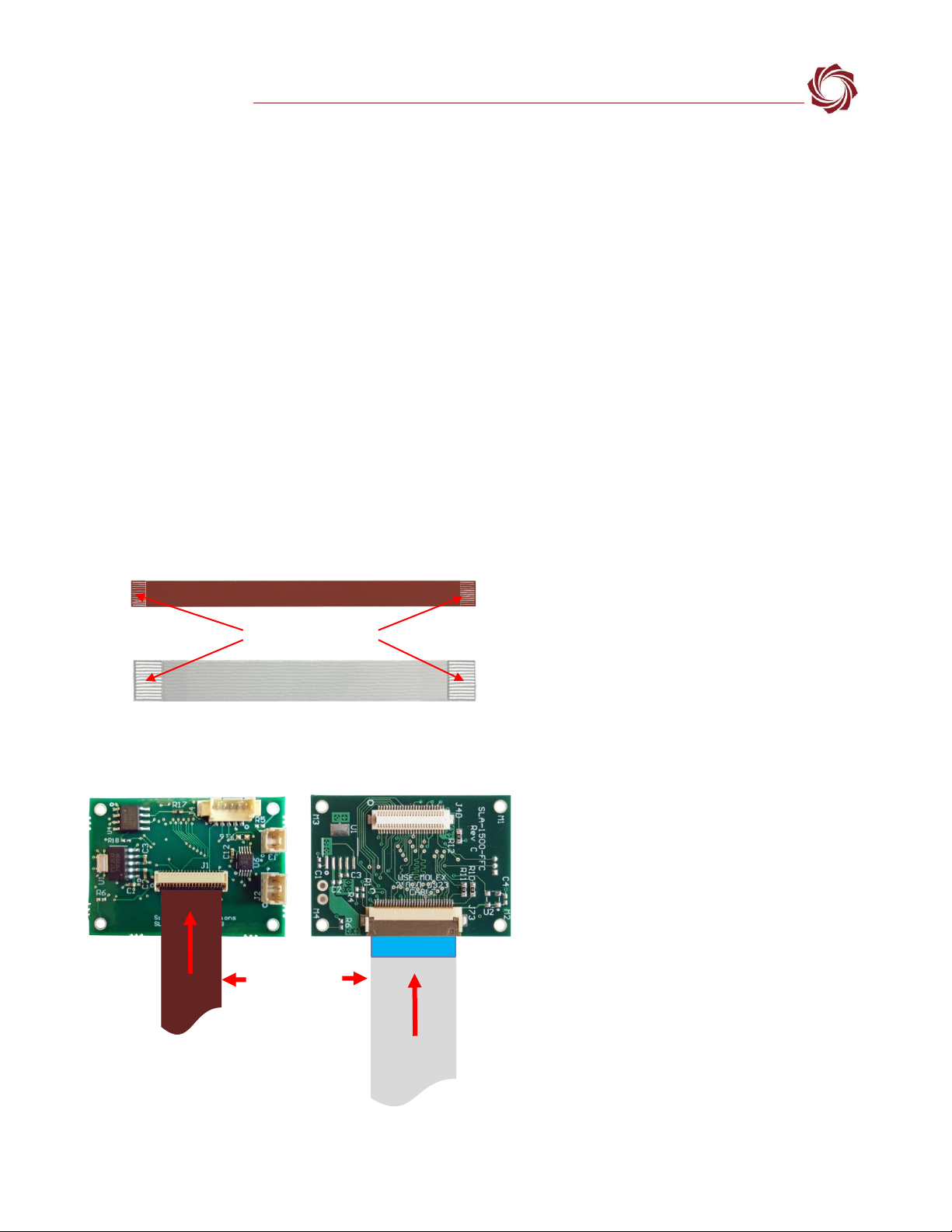
4FFC-FPC Adapter Board Connections
Some adapter boards use the Molex FFC (Flexible Flat Cable) or an FPC (Flexible Printed Circuit) cable
to connect to the camera. FFC and FPC connectors are a bottom contact design. The flip-lock is on top
of the connector and the contact surface is on the bottom. This means that the metal surface of the
cable must connect with the metal surface of the connector to have a proper interface. An incorrectly
seated cable can cause a wide range of issues and unpredictable behavior.
There are two rows of contacts on the FPC cable and connector. Unlike the FFC connector the FPC
connector is a low insertion force (LIF) design. Expect some considerable resistance pushing past the
second row of contacts, especially with a new cable. Care should be taken to prevent the cable from
over flexing.
Figure 1: FPC / FFC Connections
Connection instructions:
1. Open the flip-lock on the connector.
Use thumb or index finger. Do not
use tools or excessive force.
2. Insert the ribbon cable (with the
contact surface side down) straight
into the connector (parallel to the
PCB):
FFC: The FFC connector has a zero-
insertion force (ZIF) design. No force
is required for insertion.
FPC: Some pressure is required for a
proper interface. Expect resistance
at the second row of contacts before
it stops.
3. Ensure that the FFC / FPC cable is
fully inserted and parallel to the
mounting surface. Close the flip-lock
connector.
If the ribbon cable is moved at any
time before the flip-lock is closed
repeat the process starting at step 1.
Contact Surface
Facing Down when
Inserting
FFC Ribbon Cable and
Connector
FPC Ribbon Cable and
Connector
Ribbon Cables
Evenly Inserted
Contact Surface Side
FFC Cable
FPC Cable
ICD-1500-Adapter-Boards
© SightLine Applications, Inc. 3
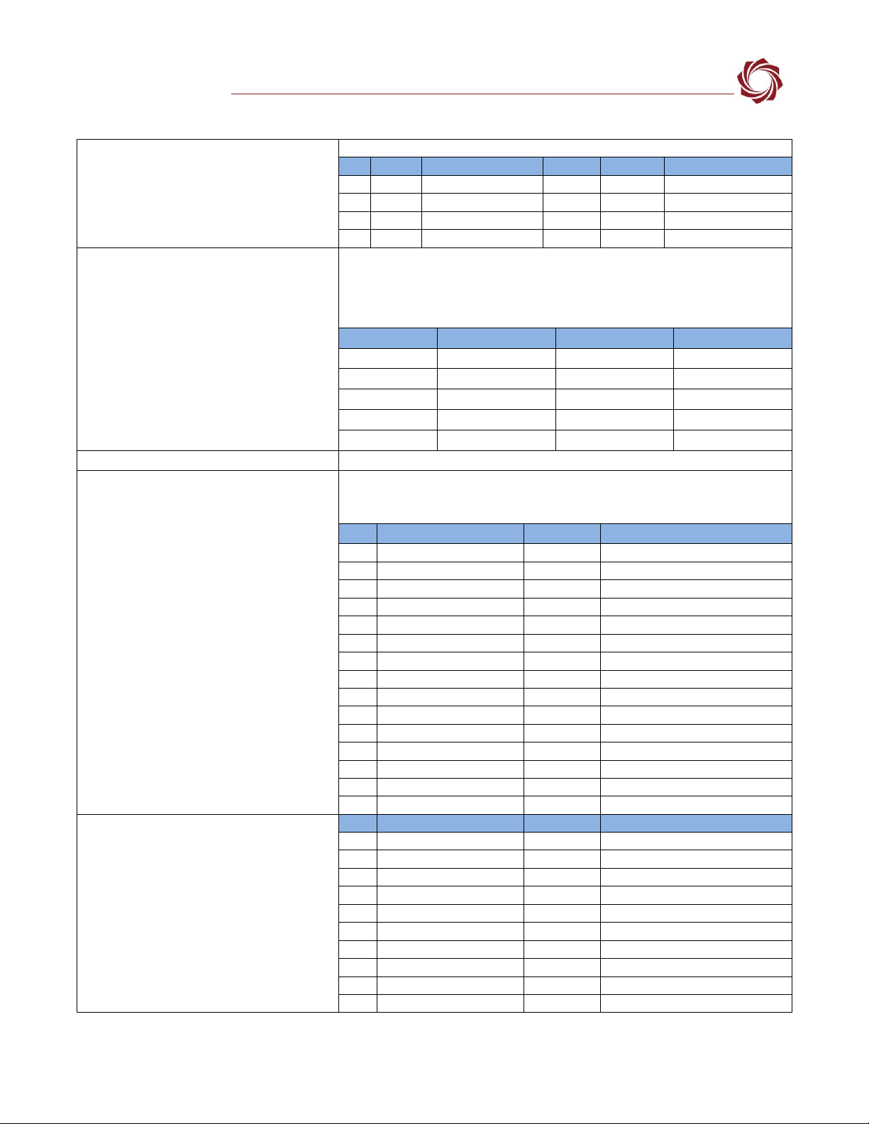
5Serial Port and GPIO Maps
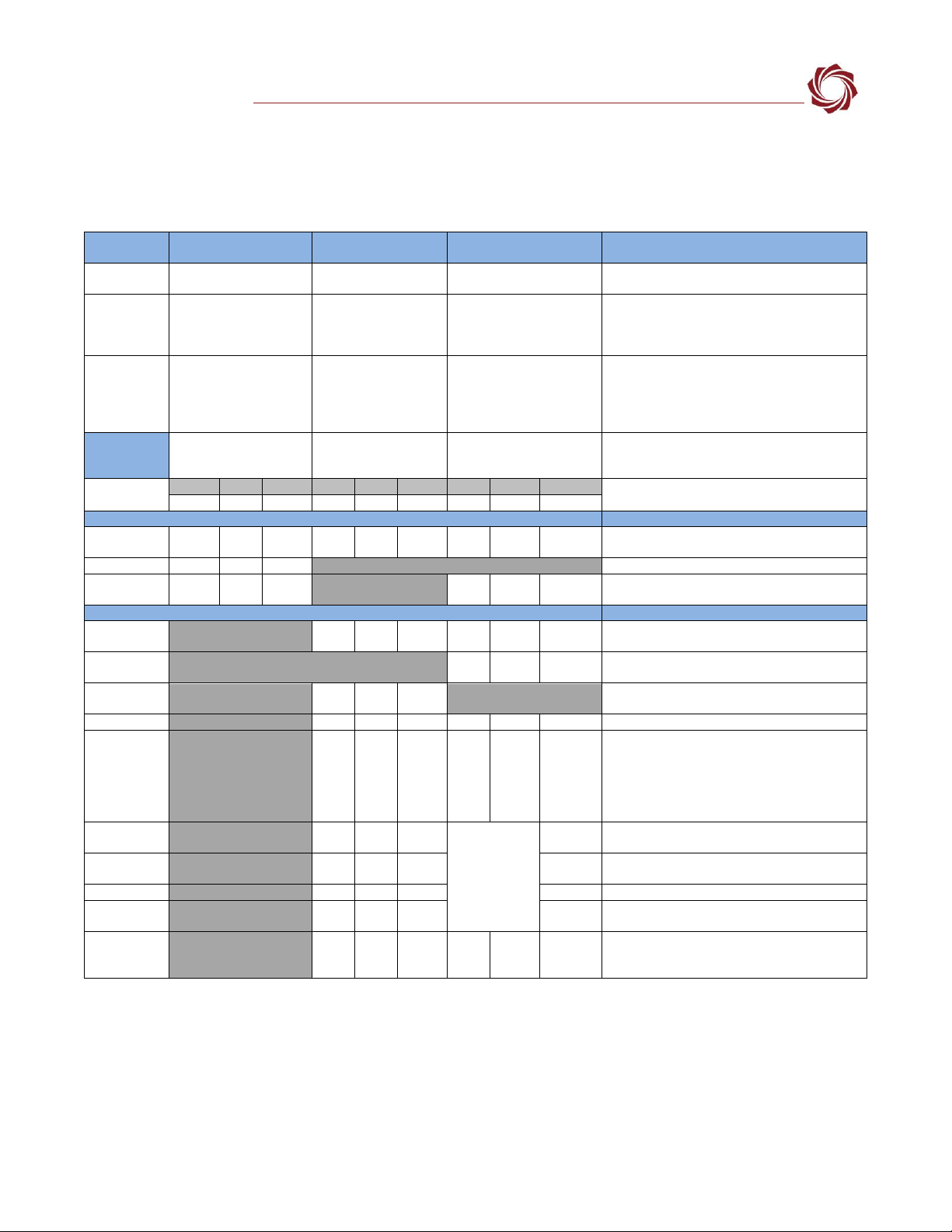
5.1 Serial Port
Table 1: 1500-OEM and Adapter Boards Serial Ports
Hardware
Reference
Serial 0
Serial 1
Serial 2
Notes
Linux
Reference
/dev/ttyO0
/dev/ttyO1
/dev/ttyO2
SOM Port
Number
A
C
B
The Torpedo SOM hardware uses a different
nomenclature in the documentation. The SOM
serial port (A, B, C) maps to the SLA serial port (0,
1, 2).
Used for:
Command and Control
and debug. Recommend
allowing access for
troubleshooting.
Command and Control
and general customer
use/passthrough.
Primarily camera control
passthrough, can be used
for general customer
use/passthrough or
command and control.
Serial Port
Access
Pinouts
Connector, Pin
Connector, Pin
Connector, Pin
1500-OEM
Rx
Tx
level
Rx
Tx
level
Rx
Tx
level
Voltage levels of serial 1 and 2 are set by VIOSEL
input J4,46.
J3,6
J3,5
3.3V
J4,15
J4,16
Note
J4,1
J4,2
Note
System Interface Boards
Notes
SLA-1500-AB
(Rev J)
J2,4
J7,2
J2,3
J7,3
RS232
J13,3
J13,2
RS232
J14,3
J14,2
RS232
SLA-1500-nAB
J2,4
J2,3
RS232
SLA-1500-mAB
J8,4
J8,3
RS232
J7,30
J7,29
3.3 V
Ser 2 (J7) is only 3.3V when connected to the FLIR
Tau camera.
Camera Interface Boards
Notes
SLA-1500-
Sony / Tamron
J6,3
J6,2
3.3V
J3,3
J1,19
J3,2
J1,18
3.3V
5V
J1 is KEL micro-coax to camera.
SLA-1500-CL
J2,19+
J2,6 -
J2,20+
J2,7 -
3.3V
Serial 2 is translated to LVDS serial for camera
comms via J2
SLA-1500-
HDMI
J1,3
J1,2
3.3V
SLA-1500-HIT
J3,3
J3,2
3.3V
J1,35
J1,36
3.3V
J1 is FFC ribbon to camera
SLA-1500-FPC
J2,3
J2,2
Note
J1,16
J1,17
Note
At ribbon cable connector J1.
Voltage levels are set on the camera side board
(see below)
If no camera-side adapter is connected to FPC
ribbon, neither serial port is available without
setting VIOSEL voltage level.
SLA-FPC -
Boson
Pin out at
camera side has
opposite pin-
out (pin 1 on
OEM to pin 39
at camera side)
1.8 V
Sets VIOSEL and serial port levels to 1.8V.
SLA-FPC-DRS
Tamarisk
1.8 V
Sets VIOSEL and serial port levels to 1.8V.
SLA-FPC -Tau
3.3 V
Sets VIOSEL and serial port levels to 3.3 V
SLA-FPC -
Airborne
2.8 V
Sets VIOSEL and serial port levels to 2.8 V
SLA-1500-FFC
to
SLA-FFC-TAU
J2,3
J2,2
3.3 V
J1,30
J1,29
3.3 V
J1 is FFC ribbon to Tau camera.
Voltage levels set by Tau camera so only 3.3 V
when camera is connected.
IMPORTANT: To use serial port 1 and serial port 2, external power must be applied to VIOSEL (OEM
J4 pin 46) to set the IO voltage level. Connecting to camera interface boards and cameras sets this
IO voltage level.
ICD-1500-Adapter-Boards
© SightLine Applications, Inc. 4
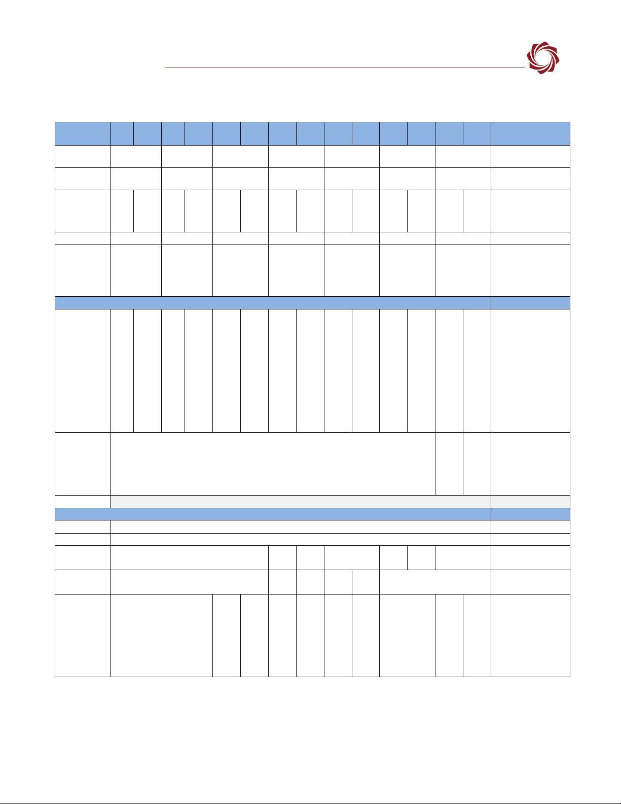
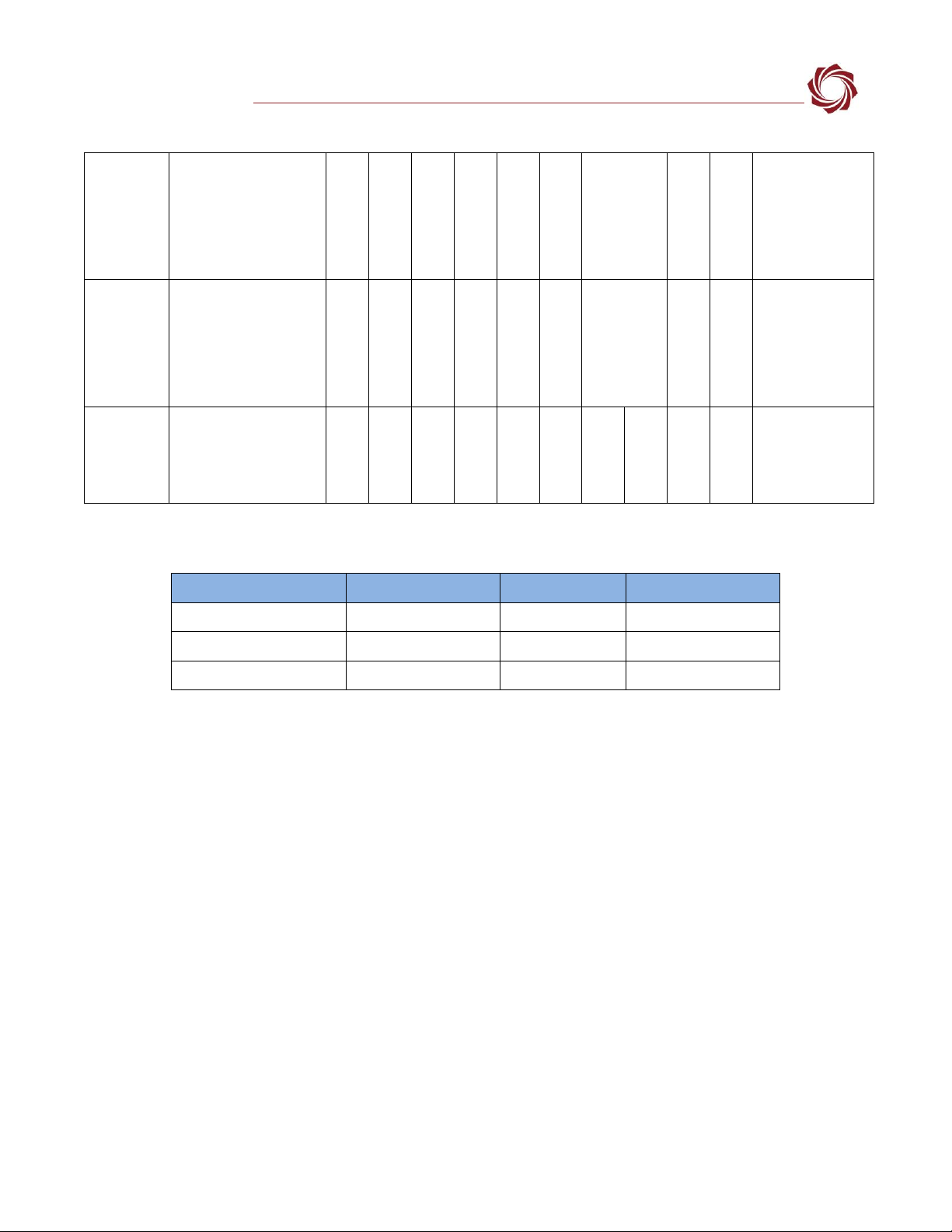
5.2 GPIO Map
Figure 2: 1500-OEM Accessible GPIO Signals
SightLine
Hardware
Pin
Level
Pin
Level
Pin
Level
Pin
Level
Pin
Level
Pin
Level
Pin
Level
(3.3V)
Notes
OEM
Schematic Ref:
GPIO144
GPIO145
GPIO172
GPIO173
GPIO174
GPIO175
GPIO178
SW Signal
Name
(TBD)
(TBD)
(TBD)
(TBD)
(TBD)
(TBD)
(TBD)
1500-OEM
J5,12
1.8V
J5,9
1.8V
J4,40
Note
J4,14
Note
J4,13
Note
J4,9
Note
J4,19
3.3V
Voltage levels of four
of the J4 GPIO signals
are set by VIOSEL
input J4,46
Default State
Input
Input
Output
Input
Input
Input
Input
Default Value
Low
Low
Low
High
High
(may toggle on
Startup)
High
Low
Default value may
change based on SW
release. Contact
SightLine if this is
important
System Interface Boards
Notes
SLA-1500-AB
Test
point
label
G144
(TP5)
3.3V
Test
point
label
G145
(TP4)
3.3 V
J11,13
Note
J11,14
Note
J11,15
Note
J11,16
Note
J11,17
FFC
J10-6
Note
3.3V
J11 is pin header for
test access. Most
GPIO signal levels are
set by VIOSEL input
J11,46
If Tau camera is
connected to FFC J10,
do not tie VIOSEL on
J11 to a voltage level.
Camera will set
VIOSEL to 3.3V
SLA-1500-mAB
FFC
J7,6
3.3V
J7 is FFC ribbon to
Tau camera.
Voltage levels set by
camera so only 3.3 V
when camera is
connected.
SLA-1500-nAB
No GPIO access on this board
Camera Adapter Boards
Notes
SLA-1500-CL
No GPIO access on this board
SLA-1500-HIT
No GPIO access on this board
SLA-1500-
Sony / Tamron
J5-1
3.3V
J7-3
3.3V
SLA-1500-
HDMI
J5-3
3.3V
J3-1
3.3V
SLA-1500-FPC
with
SLA-FPC-Boson
Or
SLA-FPC-DRS
J3-2
1.8 V
J4-3
1.8 V
Voltage levels are set
on the camera side
board.
If no camera is
connected, neither
GPIO is available
without VIOSEL
gymnastics.
ICD-1500-Adapter-Boards
© SightLine Applications, Inc. 5
(1500-OEM Accessible GPIO Signals tables continued)
SLA-1500-FPC
with
Airborne
Camera
J3-2
2.8 V
J4-3
2.8 V
Voltage levels are set
on the camera side
board.
If no camera is
connected, neither
GPIO is available
without VIOSEL
gymnastics.
SLA-1500-FPC
with
SLA-FPC-Tau
J3-2
3.3 V
J4-3
3.3 V
Voltage levels are set
on the camera side
board.
If no camera is
connected, neither
GPIO is available
without VIOSEL
gymnastics.
SLA-1500-FFC
to
SLA-FFC-TAU
J3-1
3.3 V
J3-2
3.3 V
J1 is FFC ribbon to
Tau camera.
Voltage levels set by
Tau camera so only
3.3 V when camera is
connected.
Figure 3: 1500-OEM GPIO Signals Not Accessible
Schematic Signal Name
Software Signal Name
Reference Voltage
Description/Location
GPIO129
(TBD)
1.8V
LAN9221 Pin 43
GPIO171
(TBD)
1.8V
FPGA A9
GPIO179
(TBD)
3.3V
LED D2

ICD-1500-Adapter-Boards
© SightLine Applications, Inc. 6
6SLA-1500-AB
Revision:
J
Figure 4: 1500-AB Board
Dimensions:
4.4 in x 2.9 in (111.76 mm x 73.66 mm)
Weight:
51.3 grams
EAN:
EAN-Startup Guide 1500-OEM
Drawing:
SLA-1500-AB
STEP File:
SLA-1500-AB STEP
Rev History:
E: Improved labeling and hole spacing.
H: Corrections and layout improvements.
J: Manufacturability improvement.
Due to the different revisions of the 1500-AB board, contact Support for help in determining the
right board for your application.
IMPORTANT: The supply voltage level must be compatible with the camera adapter board and
connected cameras.
IMPORTANT: The 1500-AB board provides the capability to externally set the IO voltage. Do not set
VIOSEL using the J11 header and connect to a camera via the provided FFC connector. Powering
VIOSEL through both the internal regulator and an external source can have unpredictable results
and potentially damage the OEM and accessory boards.
Figure 5: 1500-AB Connector Callouts

ICD-1500-Adapter-Boards
© SightLine Applications, Inc. 7
Table 2: 1500-AB Connector Summary
Label
MFG Part Number
Function
Mates with:
J1
RCJ-044 (yellow RCA jack)
Analog video input 0
RCA cable
J2
39502-1004
5VDC power and RS232 serial 0
39500-0004
J3
Molex 53398-1471 (14-pin)
mates with J3 on OEM
Analog video, power, serial, Ethernet
SLA-CAB-1514
J4
RCJ-044
(yellow RCA jack)
Analog video output
RCA cable
J5
Molex 53398-1271
mates with J5 on OEM
JTAG, USB
Molex 51021-1200
J6
5520251-4 Modular Jack
10/100 Base-T Ethernet
Ethernet cable
J7
182-009-113R531 DB-9 Male
RS232 serial 0
DB9 cable
J8
FCI 87583-2010BLF
Type-A USB port
Type-A USB cable
J9
12-Pin 2-row Male Header
JTAG (unpopulated connector)
12-Pin ribbon cable
J10
FH12-30S-0.5SH(55)
Digital video FFC connector
AB-FF06
J11
20-Pin Male Header
Digital connector breakout (Rev C+)
Female header
J12
RCJ-044
(yellow RCA jack)
Analog video input 1
RCA cable
J13
3-Pin Molex 53047-0310
Serial port 1 at RS-232 levels (see Table 3)
Molex 051021-0300 / SLA-CAB-0303
J14
3-Pin Molex 53047-0310
Serial port 2 at RS-232 levels (see Table 3)
Molex 051021-0300 / SLA-CAB-0303
P4
Hirose DF12B-50DS-0.5V(86)
Digital video connector
SLA-1500-OEM J4 DF12B-50DP-0.5V(86)
Table 3: 1500-AB Connector Descriptions
Connector J1: Analog Video Input 0
NTSC and PAL analog video input 0.
Connector J2: Power + RS-232 Serial Port 0
Provides 5V power to 1500-OEM, as well as access to serial port 0 at RS232
levels.
If the 1500-SONY or 1500-HITACHI board is also connected, which provide
power to the OEM via OEM J4, DO NOT turn on switch SW1.
Serial 0 is connected to both J2 and J7. Do not connect to serial port on
both connectors at the same time.
Pin
Signal
Description
1
Power
4.5V - 5.5V
2
GND
Ground
3
TX 0
RS-232C level serial port. Share ground with PIN 2.
4
RX 0
Connector J3: Analog Video, Power, Serial
0, Ethernet to OEM
This port uses the standard pinout defined in Appendix - Standard Connector
#5
Connector J4: Analog Video Output
NTSC analog video output.
Connector J5: FPGA JTAG, USB
(only rarely connected)
Pin
Signal
Pin
Signal
1
USB VBUS
7
FPGA TMS
2
USB-
8
FPGA TDI
3
USB+
9
GPIO145 at 1.8V IO
4
USBID
10
FPGA TRST
5
GND
11
FPGA TDO
6
FPGA TCK
12
GPIO144 at 1.8V IO
ICD-1500-Adapter-Boards
© SightLine Applications, Inc. 8
(1500-AB Connector Descriptions continued)
Connector J6: 10/100 Base-T Ethernet
Provides 10/100Base-T access using a standard Ethernet modular jack.
Pin
Signal
Description
Pin
Signal
Description
1
TX+
ORANGE + WHITE
5
NC
2
TX-
ORANGE
6
RX-
GREEN
3
RX+
GREEN + WHITE
7
NC
4
NC
8
NC
Connector J7: Standard DB-9 access to RS-
232 Serial Port 0
Allows for serial port console to PC at RS232 levels. Converted on board to
3.3V TTL needed by 1500-OEM.
Serial 0 is connected to both J2 and J7. Do not connect to serial port on
both connectors at the same time.
Pin
Signal
Pin
Signal
1
NC
6
NC
2
RX 0 (RS232)
7
NC
3
TX 0 (RS232)
8
NC
4
NC
9
NC
5
Ground
Connector J9: JTAG
Provides FPGA JTAG Access. Unpopulated by default.
Connector J10: FFC Digital Video
Connector
* VIOSEL out must match the camera
voltage level for Digital Data, Pixel Clock,
Line Valid and Frame Valid signals. This is
+3.3V level for most cameras. This is used
by the 1500-OEM for level translation.
This connector is used to connect the board to various cameras using an FFC
cable with a custom FFC-XXX board on the other side, where XXX stands for
the individual camera being used.
Pin
Description
Pin
Description
1
Camera TX
2
Camera RX
3
NC
4
NC
5
Ground
6
Digital Data 13
7
Digital Data 12
8
Digital Data 11
9
Digital Data 10
10
Digital Data 9
11
Digital Data 8
12
Digital Data 7
13
Digital Data 6
14
Digital Data 5
15
Digital Data 4
16
Digital Data 3
17
Digital Data 2
18
Digital Data 1
19
Digital Data 0
20
Ground
21
Pixel Clock Out
22
Frame Valid
23
Line Valid
24
NC
25
NC
26
VIOSEL out (to OEM)*
27
+5V Camera power in
28
+5V Camera power in
29
Ground
30
Ground
Connector J11: Digital Connector Breakout
Pin
Signal
Pin
Signal
1
RX2
2
RX1
3
TX2
4
TX1
5
GROUND
6
GROUND
7
I2C2SCL
8
I2C2SDA
9
VIOSEL
10
3.3VDC
11
GROUND
12
TAUDET (Active Low)
13
GPIO172
14
GPIO173
15
GPIO174
16
GPIO175
17
GPIO178
18
EXTSYNC
19
GROUND
20
5VDC
ICD-1500-Adapter-Boards
© SightLine Applications, Inc. 9
(1500-AB Connector Descriptions continued)
Connector J12: Analog Video Input 1
NTSC and PAL analog video input 1.
Connector J13: Serial Port 1 Connector
This serial port uses the standard pinout defined in Appendix - Standard
Connector #1. The voltage levels are RS232.
Connector J14: Serial Port 2 Connector
This serial port uses the standard pinout defined in Appendix - Standard
Connector #1. The voltage levels are RS232.
Connector P4: Digital Video Connector
This serial port uses the standard pinout defined in Appendix - Standard
Connector #3. The 1500-OEM plugs directly onto this connector.
6.1 Test Points
Table 4: 1500-AB Test Points
GPIO 144 and 145 are also available at
3.3V as test points.
Label
Description
G145
GPIO 145 (test point 4)
G144
GPIO 144 (test point 5)
GND
Ground
3V3_LOC
3.3V Supply for IO and VIOSEL
5V_1500
Switched 5V Supply to 1500-OEM
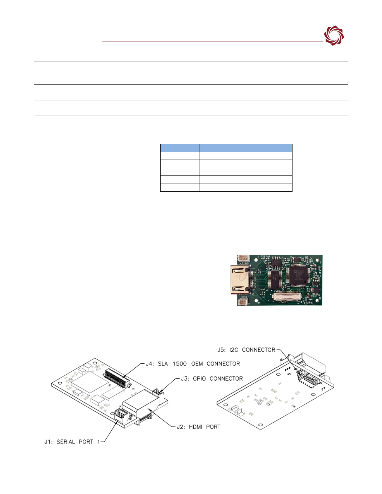
7SLA-1500-HDMI
The 1500-HDMI board provides an interface to digital HDMI cameras.
IMPORTANT: If you are using a 1500-OEM Rev C board see Appendix A - Missing Driver Chip in the
ICD-1500-OEM for more information.
Revision:
D
Figure 6: 1500-HDMI Board
Dimensions:
1.83 in x 1.09 in (46.45 mm x 27.69 mm)
Weight:
7.63 grams
EAN:
EAN-HDMI-Input
Drawing:
SLA-1500-HDMI
STEP File:
SLA-1500-HDMI STEP
Rev History:
C: PEM nuts added to ease assembly.
D: Added I2C and GPIO connectors.
Figure 7: 1500-HDMI Connector Callouts
ICD-1500-Adapter-Boards
© SightLine Applications, Inc. 10
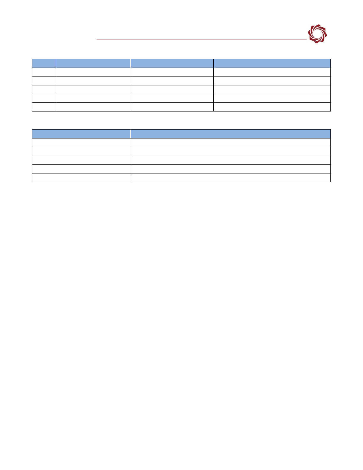
Table 5: 1500-HDMI Connector Summary
Label
MFG Part Number
Function
Mates with:
J1
3-Pin Molex 53047-0310
Serial port 1
Molex 051021-0300 / SLA-CAB-0303
J2
10029449-001RLF
HDMI receptacle (TYPE A)
HDMI plug (TYPE A)
J3
2-Pin Molex 53047-0210
GPIO connector
Molex 051021-0200 / SLA-CAB-0202
J4
DF12B-50DS-0.5V(86)
Digital Video Connector
SLA-1500-OEM J4 DF12B-50DP-0.5V(86)
J5
5-Pin Molex 53261-0571
I2C connector
Molex 051021-0500 / SLA-CAB-0502
Table 6: 1500-HDMI Connector Descriptions
Connector
Description
Connector J1: Serial Port 1 Connector
This port uses the standard pinout defined in Appendix - Standard Connector #1.
Connector J2: HDMI
This port uses the standard pinout defined in Appendix - Standard Connector #6.
Connector J3: GPIO Port
This port uses the standard pinout defined in Appendix - Standard Connector #4.
Connector J4: Digital Video Connector
This port uses the standard pinout defined in Appendix - Standard Connector #3.
Connector J5: I2C Port
This port uses the standard pinout defined in Appendix - Standard Connector #2.
7.1 Hardware Setup
See the EAN-HDMI-Input and EAN-Digital Video Configuration documents for setup and configuration
information.
1500-HDMI converts HDMI camera signals to parallel digital video that can be acquired by the 1500-
OEM board.
The 1500-OEM board must be configured to accept the converted parallel digital video signal. This
configuration will be used to set the HDMI camera format.
Configuration uses the generic digital setup to specify the timing parameters of parallel digital camera
input data. See the associated documents for more details.
Pixel Clock rates are limited to 74.25MHz by the 1500-OEM hardware. This limits the maximum input
formats of 1080P30 and 720P60. Image processing limits frame rate to 30 Hz. 720P60 format video can
be supported by using the Skip Frames feature. 1080P60 video cannot be acquired as the pixel clock
rate is above 74.25MHz.
The HDMI board will send EDID data to the attached camera with the desired format, e.g., 720P30. The
camera can still send whatever format data it chooses.
The GoPro and other cameras generally ignore the frame rate portion of the request (P30) and
generate (P60) video. This is acceptable for 720P modes, but 1080P60 cannot be acquired. For this
reason, an HDMI camera should be used that only supports 1080P30.

ICD-1500-Adapter-Boards
© SightLine Applications, Inc. 11
7.2 Camera Support
The cameras shown in Table 7 have been tested and verified to work with the 1500-HDMI board.
When changing camera settings, cycle power on the camera. Make sure Auto-Chop is turned off.
Selecting a resolution through camera setup may not result in matching HDMI output. GoPro Hero
white setup in 720P30 will still output 720P60 HDMI video. However, it will record 720P30 to the
internal MicroSD Card.
Some cameras may require an installed MicroSD card to enable HDMI output. Test settings with an
HDMI capable computer monitor.
Table 7: Supported HDMI Cameras
GoPro Hero3+ Black (CHDHX-302)
Can only be run in 720P and 480P modes. The 1080P mode defaults to P60 frame rate and cannot be acquired. The
following values will generate 720P30 and 480P30 video.
H
V
D
VFP
HFP
Flags
Skip Frames
Camera Setting
480
720
8
30
60
1
1
WVGA 240 FPS
720
1280
8
20
222
1
1
720 60 FPS
GoPro Hero3 White (CHDHE-302)
Can be run in 1080P, 720P and 480P modes. The 1080P mode defaults to 1080I60 and the HDMI board de-interlaces the
video. The following values will generate 1080P30, 720P30 and 480P30 video.
480
720
8
30
60
1
1
WVGA 60 FPS
720
1280
8
20
222
1
1
720 60 FPS
1080
1920
8
38
148
1
0
1080 30 FPS
Canon HD CMOS PRO Camcorder (XA-25)
Can be run in 720P and 480P modes. The following values will generate 720P30 and 480P30 video.
480
720
8
30
60
1
1
Auto HDMI
720
1280
8
20
222
1
1
Auto HDMI
Sony Handycam Camcorder (HDR-CX220)
Can be run in 720P and 480P modes. The following values will generate 720P30 and 480P30 video.
480
720
8
30
60
1
1
Auto
720
1280
8
20
222
1
1
Auto
7.2.1 DVI
There are several HDMI-to-DVI converters on the market. Most of them consist of cables that transmit
the digital video lines from HDMI connector to the DVI connector (DVI-D).
IMPORTANT: If converting from HDMI to DVI be aware that not all monitors or devices are able to
convert from the YUV 4:2:0 (YCbCr) format provided by the 1500-HDMI to an RGB video format
typically expected by DVI.
ICD-1500-Adapter-Boards
© SightLine Applications, Inc. 12
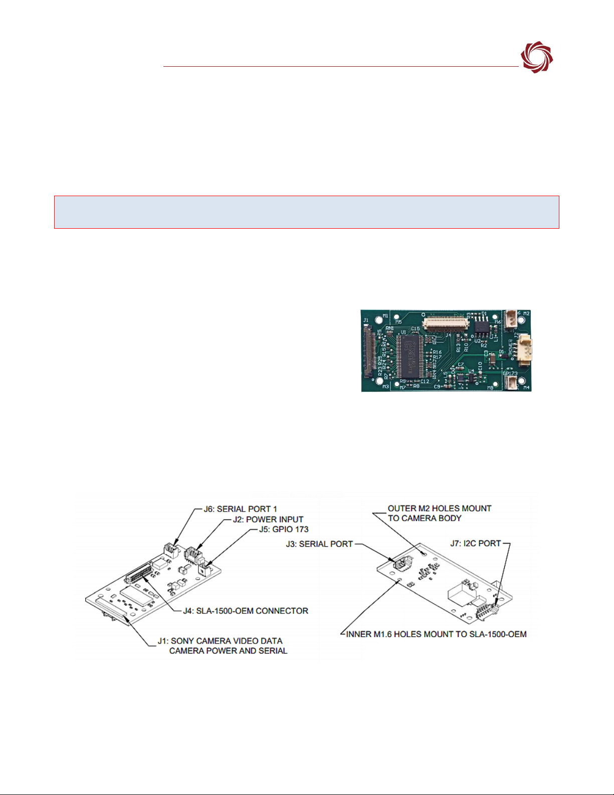
8SLA-1500-Sony /Tamron
The Sony block cameras and the Tamron MP1010M-VC camera share the same camera interface
board.
The 1500-Sony / Tamron board routes digital video from the camera to the 1500-OEM J4. The 1500-
OEM can be configured to passthrough commands using Serial Port 2. Users can also directly control
the camera using the J3 connector on this board.
CAUTION: Power to the 1500-OEM board is provided through the 1500-Sony interface board through the J2 12 VIN
connector. Powering the OEM through the J3 power pins and through the 1500-Sony board can damage the OEM.
For some Sony cameras, such as the 6300, it will also provide the analog output from the camera to
Video Port 1 on the 1500-OEM. This can be useful for debugging.
See the EAN-Sony-Compatible-Block-Cameras document for setup and configuration information for
Sony and Tamron cameras.
Revision:
E
Figure 8: 1500-Sony / Tamron Board
Dimensions:
2.25 in x 1.05 in (57.2 mm x 26.7 mm)
Weight:
8.1 grams
EAN:
EAN-Sony-Compatible-Block-Cameras
Drawing:
SLA-1500-Sony
SLA-1500-Sony Exploded
STEP File:
SLA-1500-Sony STEP
Rev History:
C: Improved hole spacing.
D: Added serial and GPIO ports.
E: Added level translator between 5V Sony serial
lines and OEM 3.3V serial line.
Figure 9: 1500-Sony / Tamron Connector Callouts
ICD-1500-Adapter-Boards
© SightLine Applications, Inc. 13
Table 8: 1500-Sony /Tamron Connector Summary
Label
MFG Part Number
Function
Mates with:
J1
KEL USL00-30L-A
Digital camera data to Sony
USL20-30SS-010.0-C1
J2
4-Pin Molex 53398-0471
Power
Molex 51021-0400 / SLA-CAB-0401
J3
3-Pin Molex 53048-0310
3.3V TTL Serial 2 direct to Sony
Molex 051021-0300 / SLA-CAB-0302
J4
Hirose DF12B-50DS-0.5V(86)
Digital video connector
SLA-1500-OEM J4 DF12B-50DP-0.5V (86)
J5
2-Pin Molex 53047-0210
3.3V GPIO
Molex 051021-0200 / SLA-CAB-0202
J6
3-Pin Molex 53047-0310
3.3V TTL Serial 1 to 1500-OEM
Molex 051021-0300 / SLA-CAB-0303
J7
5-Pin Molex 53261-0571
3.3V TTL I2C connector
Molex 051021-0500 / SLA-CAB-0502
1The KEL ribbon cable length should be as short as possible to ensure video quality and reduce EMI susceptibility. SightLine
provides a 10cm cable with camera interface kits. A KEL cable length greater than 15cm is not recommended. There are
COTS sources for alternate length KEL cables to help with custom integrations.
Table 9: 1500-Sony /Tamron Connector Descriptions
Connector J1: Digital Camera Data to Sony
See Sony or Tamron technical reference manuals for more information
and pinout details. See KEL ribbon cable note in Table 8above.
Connector J2: Power and Ground
Use with SLA-CAB-1504 or similar.
Pin
Signal
Description
1
Power +12V
Provides power to the camera and the
1500-OEM. Powering the OEM through the
J3 power pins and through the 1500-Sony
board can damage the OEM.
2
3
Ground
4
Connector J3: Serial Port 2
This port uses the standard pinout defined This serial port uses the
standard pinout defined in Appendix - Standard Connector #1. This
connector allows serial commands to be sent directly to the camera.
When using this connector to talk directly to the camera, in Panel Plus set
Serial Port 2 to Port Not Used.
Connector J4: Mates to 1500-OEM J4
This port uses the standard pinout defined in Appendix - Standard
Connector #3. The 1500-OEM plugs directly onto this connector.
Connector J5: GPIO Port
This port uses the standard pinout defined in Appendix - Standard
Connector #4. Connects to GPIO173.
Connector J6: Serial Port 1
This port uses the standard pinout defined in Appendix - Standard
Connector #1. The voltage levels are 3.3V TTL.
Connector J7: I2C Port
This port uses the standard pinout defined in Appendix - Standard
Connector #2. The voltage levels are 3.3V TTL. This port can be used for
controlling accessories such as lenses.
ICD-1500-Adapter-Boards
© SightLine Applications, Inc. 14
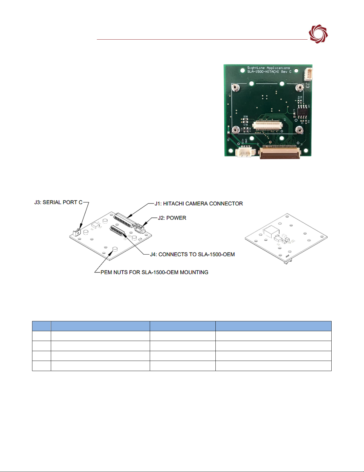
9SLA-1500-HIT
Revision:
C
Figure 10: 1500-HIT
Dimensions:
1.81 in x 1.90 in (46.0 mm x 48.3 mm)
Weight:
10.6 grams
EAN:
EAN-Hitachi-Block-1500-OEM
Drawing:
SLA-1500-Hitachi
STEP File:
SLA-1500-HITACHI STEP
Rev History:
B: Initial production release.
C: Serial port 1 (C) connector added. One mounting
hole added.
Figure 11: SLA-1500-HIT Connector Callouts
Table 10: 3000-HIT Connector Summary
Label
MFG Part Number
Function
Mates with:
J1
36-Pin Hirose FH12-36-0.5SH(55)
Hitachi Camera connector
SLA-CAB-HC36 (MFG: 15266-0387)
J2
4-Pin Molex 53398-0471
Power
Molex 51021-0400 / SLA-CAB-0401
J3
3- Pin Molex 53047-0310
Serial port 1 (C)
Molex 051021-0300 / SLA-CAB-0303
J4
50-Pin Hirose DF12B-50DS-0.5V(86)
Digital video connector
SLA-1500-OEM J4 DF12B-50DP-0.5V(86)

ICD-1500-Adapter-Boards
© SightLine Applications, Inc. 15
Table 11: 1500-HIT Connector Descriptions
Connector J1: Hitachi Video Connector
Pin
Signal
Pin
Signal
Pin
Signal
1
Ground
13
COUT(1)
25
DIG_CLK
2
YOUT(0)
14
COUT(2)
26
Ground
3
YOUT(1)
15
COUT(3)
27
Ground
4
YOUT(2)
16
Ground
28
Ground
5
YOUT(3)
17
COUT(4)
29
Ground
6
Ground
18
COUT(5)
30
Ground
7
YOUT(4)
19
COUT(6)
31
DC_IN
8
YOUT(5)
20
COUT(7)
32
DC_IN
9
YOUT(6)
21
Ground
33
DC_IN
10
YOUT(7)
22
VSYNC
34
Ground
11
Ground
23
HSYNC
35
TX
12
COUT(0)
24
Ground
36
RX
Connector J2: Power Connector
Pin
Signal
1
PWR_IN - 12V Nominal
2
PWR_IN - 12V Nominal
3
Ground
4
Ground
Connector J3: Serial Port 1 (C)
This port uses the standard pinout defined in Appendix - Standard Connector #1.
Connector J4: Digital Video Connector
This port uses the standard pinout defined in Appendix - Standard Connector #3.
ICD-1500-Adapter-Boards
© SightLine Applications, Inc. 16
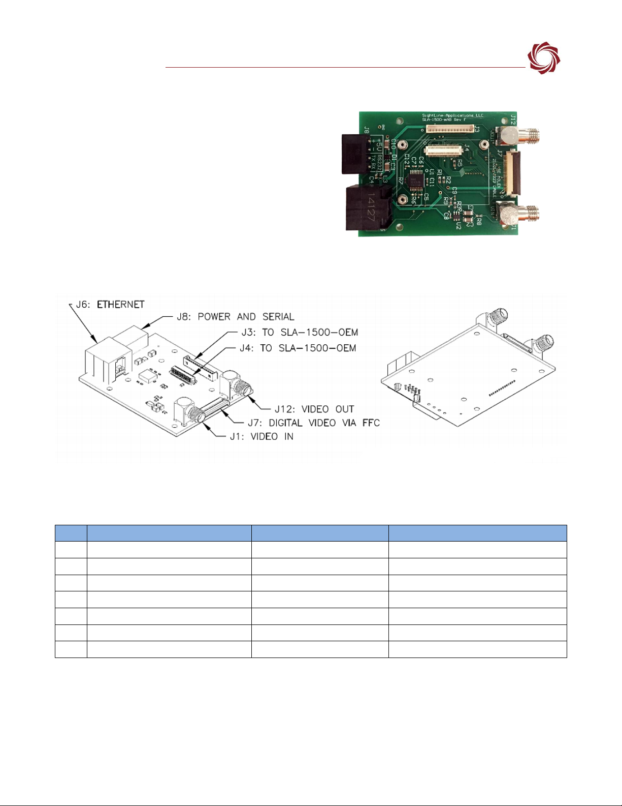
10 SLA-1500-mAB
Revision:
F
Figure 12: 1500-mAB Board
Dimensions:
2.55 in x 2 in (64.8 mm x 50.8 mm)
Weight:
24.6 grams
Drawing:
SLA-1500-mAB
STEP File:
SLA-1500-mAB STEP
Rev History:
F: Corrected routing.
G: Replaced EOL part. Changed SMA
connectors. Added mounting hole.
Figure 13: 1500-mAB Connector Callouts
Table 12: 1500-mAB Connector Summary
Label
MFG Part Number
Function
Mates with:
J1
CONSMA002
Analog video input
Standard SMA
J3
14-Pin Molex 53047-1410
1500-OEM IO connector
SLA-CAB-1514
J4
50-Pin Hirose DF12B-50DS-0.5V(86)
Digital video connector
SLA-1500-OEM J4 DF12B-50DP-0.5V(86)
J6
1-406525-1
Ethernet
Standard CAT-5e cable
J7
30-Pin Hirose FH12-30S-0.5SH(55)
Digital video FFC connector
SLA-CAB-FF06
J8
Molex 39506-1004
Power, RS-232C
Molex 039500-0004
J12
CONSMA002
Analog video output
Standard SMA

ICD-1500-Adapter-Boards
© SightLine Applications, Inc. 17
Table 13: 1500-mAB Connector Descriptions
Connector J1: Analog Video Input
NTSC and PAL analog video input.
Connector J3: Analog Video, Power, Serial 0,
Ethernet
This port uses the standard pinout defined in Appendix - Standard
Connector #5.
Connector J4: Analog Video Output
NTSC analog video output.
Connector J6: 10/100 Base-T Ethernet
Provides 10/100Base-T access using a standard Ethernet modular jack.
Pin
Signal
Description
Pin
Signal
Description
1
TX+
ORANGE + WHITE
5
NC
2
TX-
ORANGE
6
RX-
GREEN
3
RX+
GREEN + WHITE
7
NC
4
NC
8
NC
Connector J7: FFC Digital Video Connector
* VIOSEL out must match the camera voltage
level for Digital Data, Pixel Clock, Line Valid and
Frame Valid signals. This is +3.3V level for most
cameras. This is used by the 1500-OEM for level
translation.
This connector is used to connect the board to various cameras using an
FFC cable with a custom FFC-XXX board on the other side, where XXX
stands for the individual camera being used.
Pin
Description
Pin
Description
1
Camera TX
2
Camera RX
3
NC
4
NC
5
Ground
6
Digital Data 13
7
Digital Data 12
8
Digital Data 11
9
Digital Data 10
10
Digital Data 9
11
Digital Data 8
12
Digital Data 7
13
Digital Data 6
14
Digital Data 5
15
Digital Data 4
16
Digital Data 3
17
Digital Data 2
18
Digital Data 1
19
Digital Data 0
20
Ground
21
Pixel Clock Out
22
Frame Valid
23
Line Valid
24
NC
25
NC
26
VIOSEL out (to OEM)*
27
+5V Camera power in
28
+5V Camera power in
29
Ground
30
Ground
Connector J12: Analog Video Output
NTSC analog video output
Connector J8: Power + RS-232 Serial Port 0
Pin
Signal
Description
1
Power
4.5V - 5.5V
2
GND
Ground
3
TX 0
RS-232C level serial port. Share ground with PIN 2.
4
RX 0
ICD-1500-Adapter-Boards
© SightLine Applications, Inc. 18
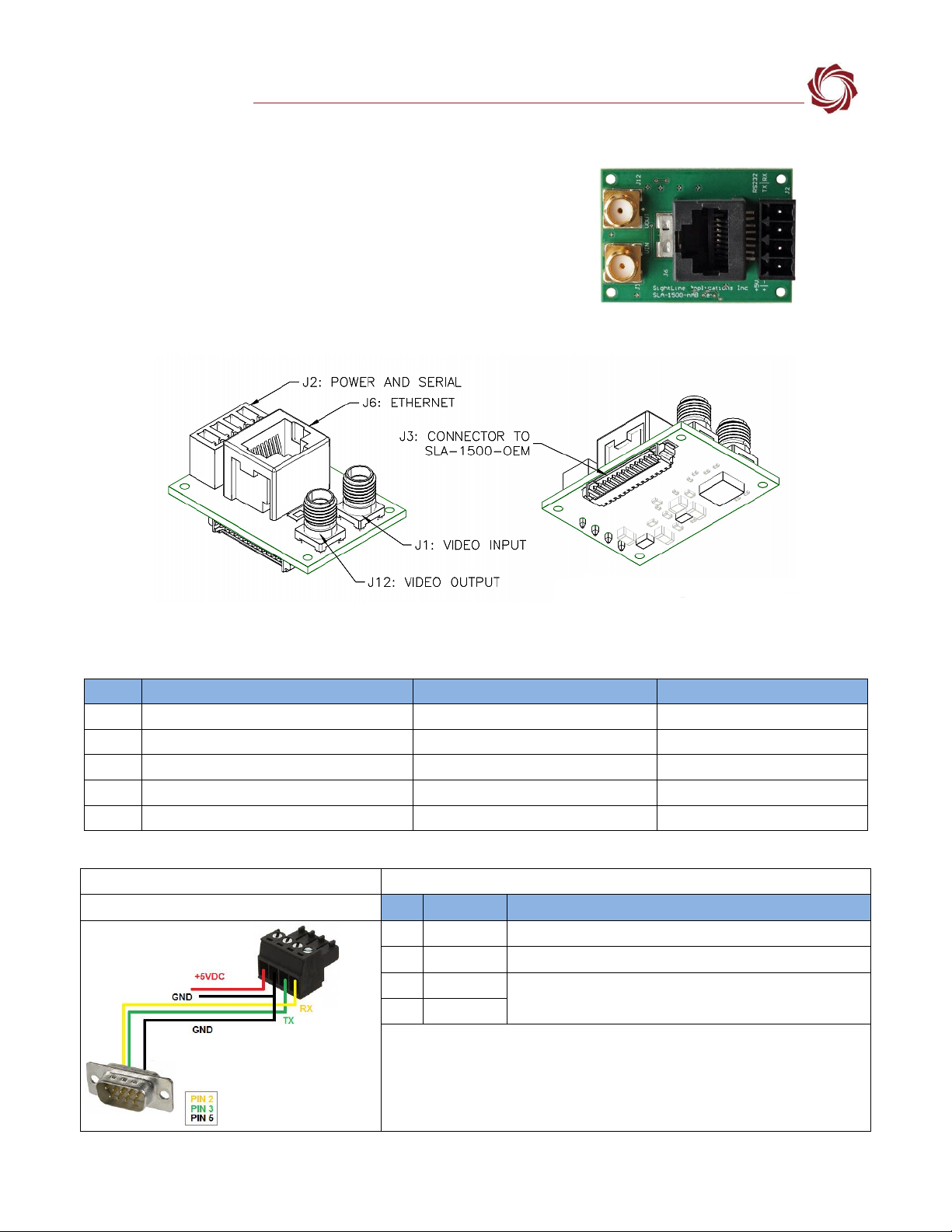
11 SLA-1500-nAB
Revision:
B
Figure 14: 1500-nAB Board
Dimensions:
1.48 in x 1.04 in (37.6 mm x 26.4 mm)
Weight:
10 grams (unverified)
Drawing:
SLA-1500-nAB
STEP File:
SLA-1500-nAB STEP
Rev History:
B: Silkscreen improvements.
Figure 15: 1500-nAB Connector Callouts
Table 14: 1500-nAB Connector Summary
Label
MFG Part Number
Function
Mates with:
J1
CONSMA001
Analog video input
Standard SMA
J2
4-Pin Molex terminal block 39501-1004
Power, RS-232C
Molex 039500-0004
J3
14-Pin Molex 53261-1471
1500-OEM IO connector
SLA-CAB-1514
J6
1-338088-3
Ethernet
Standard CAT-5e cable
J12
CONSMA001
Analog video output
Standard SMA
Table 15: 1500-nAB Connector Descriptions
Connector J1: SMA IN
75 Ohms, SMA vertical jack receptacle coax connector
Connector J2: Power + RS-232 Serial Port 0
Pin
Signal
Description
1
Power
4.5V - 5.5V
2
GND
Ground
3
TX 0
RS-232C level serial port. Share ground with PIN 2.
4
RX 0
Table of contents
Popular Adapter manuals by other brands


SIIG
SIIG 2-Port USB to RS-232 Serial Adapter Quick installation guide

Icy Box
Icy Box IB-AA508 Quick installation guide

Daikin
Daikin EKMBPP1 installation manual

Asus
Asus PCE-AC55BT quick start guide

ZyXEL Communications
ZyXEL Communications PLA4211 user guide

Renkforce
Renkforce PC2TV operating instructions


