Silego GreenPAK User manual


GreenPAK Universal
Development Board
Silego Technology Inc. www.silego.com
10/13/2014
Copyrights
Copyright © 2010 Silego Technology. The information contained herein is subject to
change without notice. Silego Technology assumes no responsibility for the use of any circuitry
other than circuitry embodied in a Silego product. Nor does it convey or imply any license
under patent or other rights. Silego products are not warranted nor intended to be used for
medical, life support, lifesaving, critical control or safety applications, unless pursuant to an
express written agreement with Silego. Furthermore, Silego does not authorize its products for
use as critical components in life-support systems where a malfunction or failure may
reasonably be expected to result in significant injury to the user. The inclusion of Silego
products in life-support systems application implies that the manufacturer assumes all risk of
such use and in doing so indemnifies Silego against all charges.
GreenPAK3 Designer™, GreenPAK3 Programmer™ and GreenPAK3™ are trademarks of
Silego Technology. All other trademarks or registered trademarks referenced herein are
property of the respective corporations.
Any Source Code (software and/or firmware) is owned by Silego Technology (Silego) and is
protected by and subject to worldwide patent protection (United States and foreign), United
States copyright laws and international treaty provisions. Silego hereby grants to licensee a
personal, non-exclusive, non-transferable license to copy, use, modify, create derivative works
of, and compile the Silego Source Code and derivative works for the sole purpose of creating
custom software and or firmware in support of licensee product to be used only in conjunction
with a Silego integrated circuit as specified in the applicable agreement. Any reproduction,
modification, translation, compilation, or representation of this Source Code except as
specified above is prohibited without the express written permission of Silego.
Disclaimer: SILEGO MAKES NO WARRANTY OF ANY KIND, EXPRESS OR IMPLIED, WITH
REGARD TO THIS MATERIAL, INCLUDING, BUT NOT LIMITED TO, THE IMPLIED
WARRANTIES OF MERCHANTABILITY AND FITNESS FOR A PARTICULAR PURPOSE.
Silego reserves the right to make changes without further notice to the materials described
herein. Silego does not assume any liability arising out of the application or use of any product
or circuit described herein. Silego does not authorize its products for use as critical
components in life-support systems where a malfunction or failure may reasonably be
expected to result in significant injury to the user. The inclusion of Silego product in a life-
support systems application implies that the manufacturer assumes all risk of such use and in
doing so indemnifies Silego against all charges. Use may be limited by and subject to the
applicable Silego software license agreement.

GreenPAK Universal
Development Board
Silego Technology Inc. www.silego.com
10/13/2014
Contents
1. Introduction……………………………………………………………………………………………4
1.1. Kit contents……………………………………………………………………………………….…4
1.2. GreenPAK3 Designer………………………………………………………………………………4
1.3. Support………………………………………………………………………………………………5
2. Getting Started……………………………………………………………………..…………………6
2.1. Introduction……………………………………………………………………………….…………6
2.2. Install Hardware……………………………………………………………………………………6
2.3. Install Software……………………………………………………………………………..………6
2.4. Uninstall Software………………………………………………………………………….………6
3. Hardware………………………………………………………………………………………………7
3.1. Overview…………………………………………………………………………………….………7
3.2. Functional Description…………………………………………………………………..…………8
3.2.1. Power Supply…………………………………………………………………………………..…8
3.2.2. USB Communication………………………………………………………………….…………8
3.2.3. GND connections……………………………………………………………………...…………8
3.2.4. Pin test points………………………………………………………………………….…………8
3.2.5. LEDs………………………………………………………………………………………………8
3.2.6. Socket connector…………………………………………………………………...……………9
3.2.7. Expansion connector……………………………………………………...……………………10
3.2.8. Pins connectivity……………………………………………………………...…………………15
4. Example projects……………………………………………………………………………………18
4.1. Project: Counter with clock enable…………………………………………………..…………18
4.2. Project: LED string with direction…………………………………………………….…………31
A. Appendix……………………………………………………………………………….……………39
A.1. Schematic…………………………………………………………………………………………39
A.2. BOM………………………………………………………………………………………………..44

GreenPAK Universal
Development Board
Silego Technology Inc. www.silego.com
10/13/2014
1. Introduction
Thank you for choosing Silego Technology products. GreenPAK Universal
Development Board allows you to develop your custom design using GreenPAK3 mixed signal
IC. You can design your own projects starting from a blank project or by altering the sample
projects provided at Silego website. GreenPAK3 chip is a mixed signal micro FPGA IC that
combines configurable standard logic, timing, analog comparators, ADC and other macro
modules in tiny 12-pin 2x3mm package when still running on very low power.
1.1. Kit contents
The GreenPAK Universal Development Board contains:
GreenPAK Universal Development Board with socket board;
USB A to mini B cable;
GreenPAK3 samples;
Quick start guide.
Inspect the contents of the kit; if you find any part missing, contact Silego for help.
1.2. GreenPAK3 Designer
GreenPAK3 Designer is an easy-to-use full-featured integrated development
environment (IDE) that allows you to specify exactly how you want the device to be configured.
This provides you a direct access to all GreenPAK3 device features and complete control over
the routing and configuration options.
GreenPAK3 Designer has simple and intuitive software interface to GreenPAK3
Universal Board that gives you a quick and easy way to develop your entire GreenPAK3
project with just one tool.
With GreenPAK3 Designer, you can:
Design the configuration which corresponds to your project needs;
Verify the project using software interface to GreenPAK3 Universal Board hardware;
With a simple-to-use and intuitive software and hardware tools you can reduce your
project development time and get to market faster.
To start working with GreenPAK3 Designer please do the following steps:
Download and install GreenPAK3 Designer software;
Configure modules that you will need for your project;
Interconnect and configure modules;
Specify the pinout;
Test your design with the GreenPAK3 Universal Board

GreenPAK Universal
Development Board
Silego Technology Inc. www.silego.com
10/13/2014
1.3. Support
Free support for GreenPAK3 Universal Board is available online at http://www.silego.com.
At : silegousa
silegochinese
silegoeurope
silegojapan
At : Silego-Technology
GreenPAK3 Designer will update itself when a new software version is detected and
available. For manual updates please go to Software & Docs page at Silego Technology
website
You can also find all these resources in the Help menu of GreenPAK3 Designer.

GreenPAK Universal
Development Board
Silego Technology Inc. www.silego.com
10/13/2014
2. Getting Started
2.1. Introduction
This chapter describes how to install and configure the GreenPAK3 Universal Board.
Chapter 3 provides the details of hardware operation.
Chapter 4 provides instructions on how to create a simple project example.
The Appendix section provides the schematics and BOM associated with the GreenPAK3
Universal Board.
2.2. Install Hardware
No hardware installation is required for this kit.
2.3. Install Software
GreenPAK3 Designer software is available free of charge from the Silego website at
Software & Docs page.
2.4. Uninstall Software
The software can be uninstalled in the way typical for your operating system. Please
refer to your operating system support documentation if you need the specific instructions or
visit Support section of this document for additional support from Silego.
GreenPAK Universal
Development Board
Silego Technology Inc. www.silego.com
10/13/2014
3. Hardware
3.1. Overview
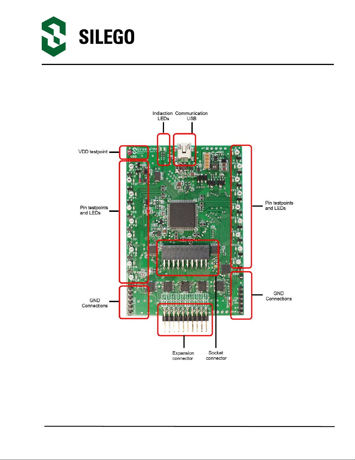
Figure 3-1. GreenPAK3 Universal Board, top view
Notification: All test points were designed only for observation of signals on the pins. Please do
not try to connect external power/signal source to test points, this will affect GreenPAK3
Universal Board functionality and may even damage it.

GreenPAK Universal
Development Board
Silego Technology Inc. www.silego.com
10/13/2014
3.2. Functional Description
3.2.1. Power Supply
Main power source of GreenPAK3 Universal Board is USB power lines. GreenPAK3
chip power supply range is 1.8-5.5 volts. The development board can provide power from 0 to
5.5V. To provide this power range the development board is enabled with a boost converter. A
Signal generator with a buffered output controls GreenPAK3 chip power rail. For more
information about GreenPAK3 electrical specification, please refer to the part datasheet.
3.2.2. USB Communication
The board has a USB communications interface that uses the USB mini-B connector, as
shown in Figure 3-2. This interface provides communication with software control tool and
supplies power to the board, as discussed in Power Supply chapter.
Figure 3-2. USB Interface
3.2.3. GND connections
There are 6 GND pins on the left side, 6 pins and 1 header on the right side. These can
be used for test equipment (oscilloscope, multimeter etc.) ground reference connection or to
connect external test circuitry ground.
3.2.4. Pin test points
Each GreenPAK3 chip pin including VDD has its own observation test point. These test
points were designed only for observation, if you need to connect an external signal source,
use a software-controlled expansion connector.
3.2.5. LEDs
All the pins except Pin2 can be connected to buffered LEDs. This option allows you to
visualize digital levels on chip pins. There are 2 selection modes:
- Buffered LED (with high impedance input);

GreenPAK Universal
Development Board
Silego Technology Inc. www.silego.com
10/13/2014
- Inverted Buffered LED (with high impedance input);
This option can be enabled in GreenPAK3 Designer.
3.2.6. Socket connector
The GreenPAK3 Universal Board is supplied with a detachable socket board (Figure
3-3). Its main purpose is to connect GreenPAK3 chip to the Development Board. It can be used
to have an easy way to use programmed chip in external circuits, or measure current
consumption of your project.
Figure 3-3.GreenPAK3 Socket Board and schematic
Figure 3-4.GreenPAK3 Socket PCB
GreenPAK Universal
Development Board
Silego Technology Inc. www.silego.com
10/13/2014
3.2.7. Expansion connector
This port was designed to connect GreenPAK3 Universal Board to external circuits and
apply external power, signal sources and loads. It can be used to apply GreenPAK3 chip into
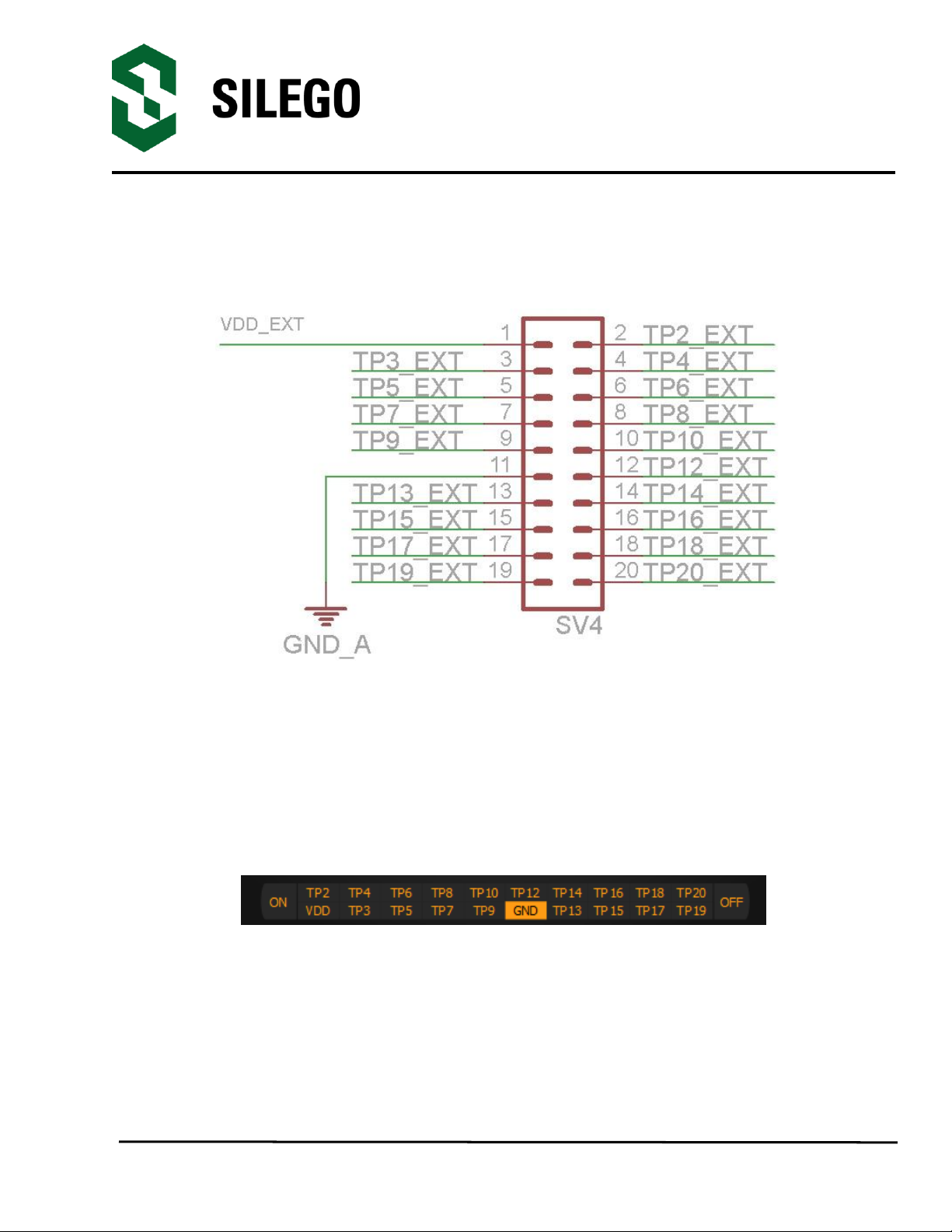
your custom design with minimum additional tools. Schematic is available on Figure 3-5.
Figure 3-5. GreenPAK3 expansion connector schematic
Each pin except PIN11 (GND) is controlled through individual analog switch. Expansion
connector is a standard 0.1” double row connector. GreenPAK3 Designer allows you to easily
open or close external pins, as it is shown on figure below. Main purpose of Expansion
connector is to connect external signal/power source safety for GreenPAK3 Universal Board.
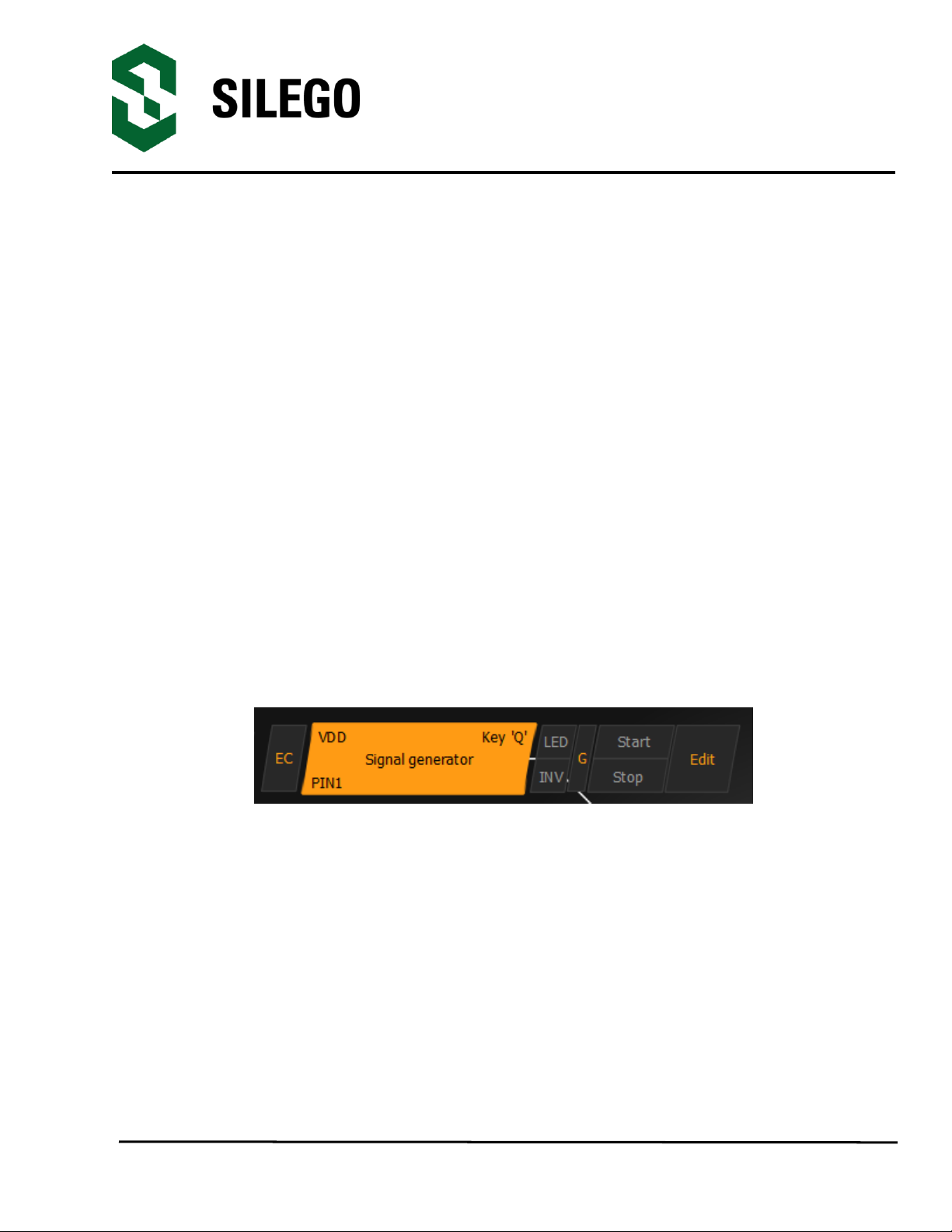
Figure 3-6. Expansion connector control in GreenPAK3 Designer
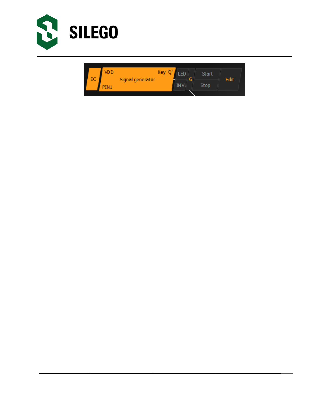
Figure 3-7 demonstrates schematic of the expansion connector control.

GreenPAK Universal
Development Board
Silego Technology Inc. www.silego.com
10/13/2014
Figure 3-7. Socket and expansion connector schematic
Expansion connector is enabled only in Emulation mode or Test mode. To enter any of
this two modes GreenPAK3 chip is required inside the socket. When the Test mode button is
pressed the software will first read the chip to verify that it was inserted and then configure the
GreenPAK3 Universal Board as it was set in Emulation Tool window. When the Test mode
button is grey then the Dev. Board is in Default state and all expansion port switches are open
(disconnected). After Emulation button is pressed, the software will automatically perform
the following steps:
GreenPAK Universal
Development Board
Silego Technology Inc. www.silego.com
10/13/2014
- check chip presence;
- open all expansion port switches (external signals/loads can be leaved connected to
expansion port);
- use internal power and load configuration to the chip
- only for case #3: adjust internal power source to external power
level -> close external power switch -> open internal power switch;
- configure board as it was set in Emulation Tool window;
Also the parasitic effects should be considered while using GreenPAK3 Universal Board in-
circuit with analog signals. The entire board circuitry along with the wiring have significant
amount of mutual capacitance and inductance. The detachable socket can also be used for
the in-circuit development with programmed chips (the board and socket connectors have
same pinout).
The GreenPAK Universal Board provides three possible ways of using expansion connector:
1) The internal power is used to run chip, no external power output is needed, external signal
sources and loads can be connected between pins and GND.
The configuration steps:
- close internal and open external power switch;
- close all used expansion port switches in the software;
- hit Emulation/Test mode button;
This is common way of using Expansion connector.
Figure 3-8. Internal power source
2) The internal power is used to run chip and external circuit (internal power source/sink
current is limited to 50mA).
The configuration steps:
- close internal power switch;
- close external power switch;
- close all used expansion port switches in the software;
- hit Emulation/Test mode button;
GreenPAK Universal
Development Board
Silego Technology Inc. www.silego.com
10/13/2014
Figure 3-9. Internal power source for GreenPAK3 chip and external board
3) The external power is used to run chip and external circuit (internal source output is in Hi-Z
state).
The configuration steps:
- open internal power switch;
- close external power switch;
- close all used expansion port switches in the software;
- hit Emulation/Test mode button (External power should be applied before this step);
Mention that GreenPAK3 chip is OTP part and "Emulation mode" allows to load the
project into GreenPAK3 chip many times, but after power loss all internal data will be lose.
Also when the GreenPAK chip is already programmed - user can use Emulation mode to
load some other project and test it on the emulation tool during the
Emulation mode, in that case emulation data will be cleared. The "Emulation" mode is not
necessary for checking programmed parts: in this case the "Test mode" is enough.
Expansion connector can be divided on 3 types of connections.
1. VDD;
2. GND;
3. Data connections.
VDD connection allows you to connect/disconnect external and internal power source. This
connection meets next requirements:
External power in range 1.8 - 5.5 volt.
High ohm voltage dividers are not recommended.
GND connection is connected directly to Development board, and cannot be controlled with
GreenPAK3 Designer.
Data connections are easiest way to connect external lines to GreenPAK3 chip. They are
software controlled switches. Every line is connected with 100Ohm resistor.

GreenPAK Universal
Development Board
Silego Technology Inc. www.silego.com
10/13/2014
Figure 3-10. Expansion connector. Pin with protection resistor.
GreenPAK Universal
Development Board
Silego Technology Inc. www.silego.com
10/13/2014
3.2.8. Pins connectivity
GreenPAK3 Universal Board allows connecting eight types of loads and signal sources.
Each source has its own special purpose.
List of available connections for each pin is presented in the table below.
Pin
Set to
VDD
Set to
GND
Pull up
Pull
down
Set
configurable
button
LED
Signal generator
Logic generator
#
1
2
3
4
5
6
7
8
VDD
-
-
-
-
-
-
+
-
Pin2
+
+
+
+
+
-
-
+
Pin3
+
+
+
+
+
+
-
+
Pin4
+
+
+
+
+
+
-
+
Pin5
+
+
+
+
+
+
-
+
Pin6
+
+
+
+
+
+
+
+
Pin7
+
+
+
+
+
+
+
+
Pin8
+
+
+
+
+
+
+
+
Pin9
+
+
+
+
+
+
-
+
Pin10
+
+
+
+
+
+
+
+
Pin12
+
+
+
+
+
+
+
+
Pin13
+
+
+
+
+
+
+
+
Pin14
+
+
+
+
+
+
+
+
Pin15
+
+
+
+
+
+
-
+
Pin16
+
+
+
+
+
+
-
+
Pin17
+
+
+
+
+
+
-
+
Pin18
+
+
+
+
+
+
-
+
Pin19
+
+
+
+
+
+
-
+
Pin20
+
+
+
+
+
+
-
+
GreenPAK Universal
Development Board
Silego Technology Inc. www.silego.com
10/13/2014
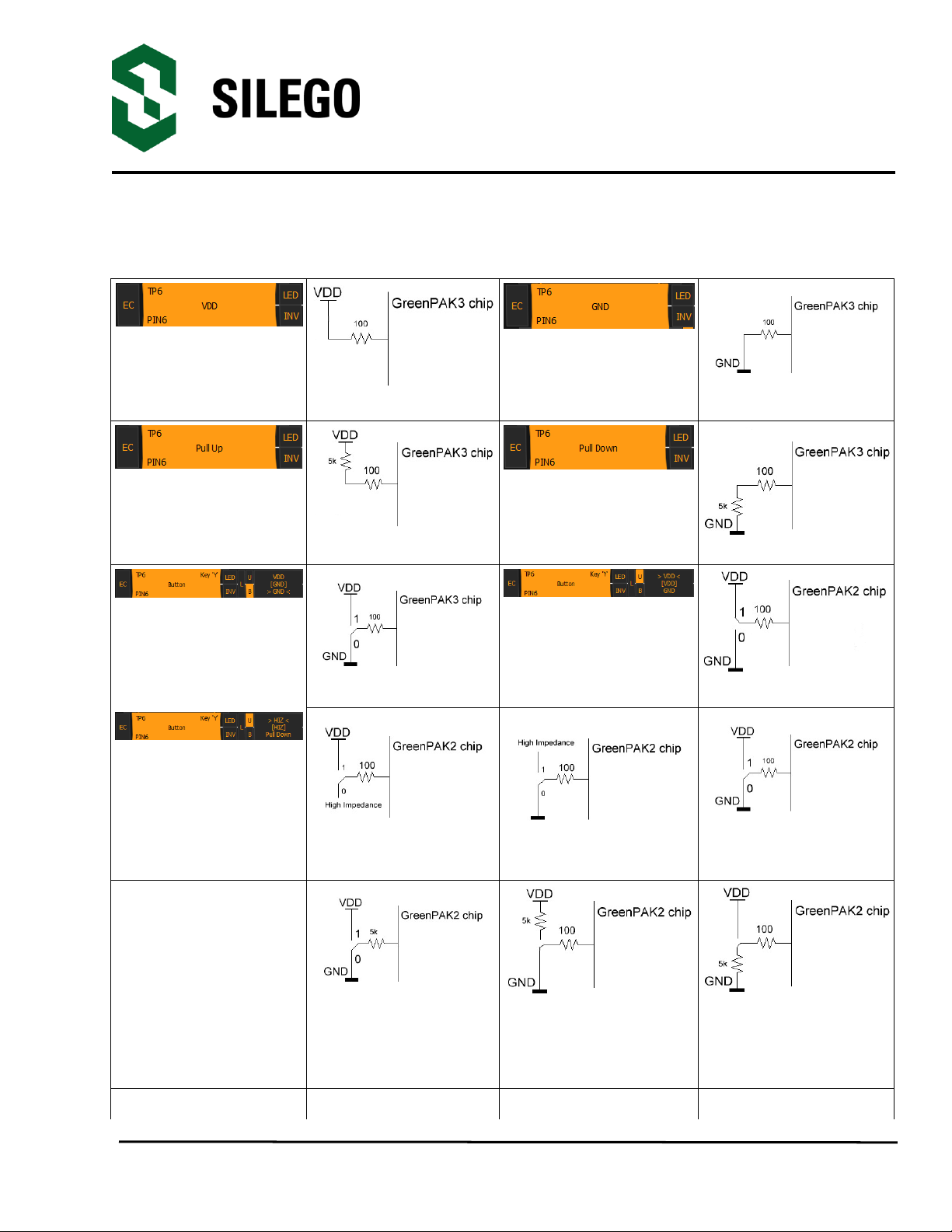
Pin signal sources/loading schematics:
Set to VDD
Set to VDD
Set to GND
Set to GND
Pull up
Pull up
Pull down
Pull down
Button pressed
Button pressed
Button released
Button released
Button with different
configurations
Button
VDD –HI-Z
Button
HI-Z - GND
Button
VDD - GND
Button
Pull up - Pull down
Button
Pull up - GND
Button
VDD –Pull down
GreenPAK Universal
Development Board
Silego Technology Inc. www.silego.com
10/13/2014
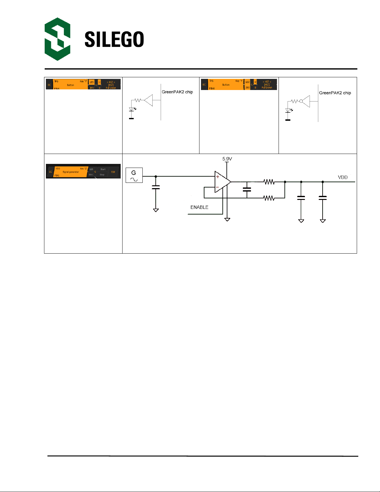
LED
Buffered LED
LED
Inverted buffered LED
VDD Signal
generator*
VDD Signal generator
*- VDD Signal generator works similar to other Signal generators but has wider output voltage
range. It can provide maximum supply level of 5.5 V.

GreenPAK Universal
Development Board
Silego Technology Inc. www.silego.com
10/13/2014
4. Example projects
4.1. Project: Counter with clock enable
The first example project - Counter with clock enable is very simple. For this project we will
need:
- 2 digital inputs;
- 1 digital output;
- 1 Look-Up table with two inputs;
- 1 Counter.
Figure 4-1. GreenPAK3 Designer

GreenPAK Universal
Development Board
Silego Technology Inc. www.silego.com
10/13/2014
Figure 4-2. GreenPAK3 Components list
GreenPAK Universal
Development Board
Silego Technology Inc. www.silego.com
10/13/2014
All these components can be found in components list. If there are no components on a
work area - make sure this component is enabled.
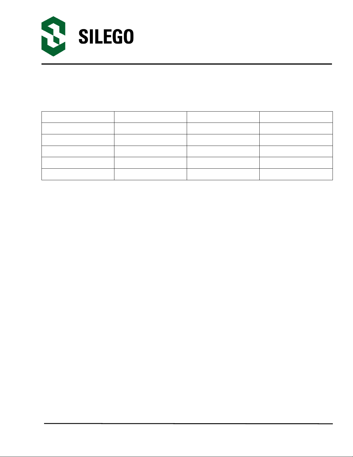
Pin Configuration
Pin #
Pin Name
Type
Pin Description
1
VDD
PWR
Supply Voltage
2
Clock
Digital input
Digital Input
3
Enable
Digital input
Digital Input
11
GND
GND
Ground
20
Counter Output
Push pull output
Digital Output
On Figure 4-1 there are shown all the components used in project; next step is to configure
selected blocks. Double click on PIN20 to open “Properties” panel. Select “1x push pull” from
the drop-down menu in Pin20 properties and hit “Apply” button
Table of contents
Other Silego Motherboard manuals

Popular Motherboard manuals by other brands

Asus
Asus P4PE-X troubleshooting guide

SMART Embedded Computing
SMART Embedded Computing MVME7100 Programmer's reference

MikroTik
MikroTik RouterBOARD 411AR user manual

Intel
Intel SR870BN4 - Server Platform - 0 MB RAM Technical advisory

Texas Instruments
Texas Instruments DRV8873 EVM Series user guide

ASROCK
ASROCK H61M-GS user manual


