SILENT KNIGHT 5128 User manual

1
1. Introduction
The Silent Knight Model 5128/29 is a low-cost slave communicator that meets the requirements for UL 864,
NFPA 72 Central Station Fire Protective Signaling System and Remote Signaling.
NOTE: In this manual, a rectangle represents a key that you press. For example, “Press ENTER ” means
“Press the <ENTER> key.”
1.1 Features
• Compatibility with the Security Industry Association (SIA) reporting format and six other standard
reporting formats.
• Four channel (zone) inputs for system status reporting: fire alarm (channel or zone 1); system
troublechannel 2 (or zone 2); supervisorychannel 3 (or zone 3); and miscellaneouschannel 4
(or zone 4).
• Optional two-number dialing with same or different account codes and reporting formats. Alarms, troubles,
disables, and tests can be programmed to be reported to either or both numbers.
• Programmable as rotary-only or as Touch-Tone/rotary dialing.
• Built-in dual phone line-seizure circuit.
• Dual phone line monitor circuits.
• Transient voltage protection of phone lines.
• Built-in audible trouble buzzer with a loudness of 80 decibels (dB) at 30 cm (ie, 300 mm or, approximately,
12 inches).
• One relay output, programmable for alarm or trouble conditions.
• Light-emitting diodes (LEDs), visible from front of plastic enclosure, indicating: trouble condition
(yellow); presence of DC power (green), phone line 1 trouble (red); and phone line 2 trouble (red).
• Easy, English-language programming using Model 5230 Remote Annunciator.
• Test features: Real-time programmable 24-hour communicator test; manual communicator test; automatic
daily test (programmable from 5230 annunciator).
• Fuseless design, 24 VDC.
• Electrically erasable read-only memory (EEPROM) for nonvolatile storage of all programmable option
data. Eliminates the need to reprogram the communicator if power is lost.
• Built-in watchdog circuit that monitors the operation of the 5128/29 and resets the communicator if a fault
is detected.
(list continued on next page)

2
Features (continued from previous page)
• Active high, contact closure or direct monitoring input for monitoring control panel’s primary power.
• Compatibility with many Underwriters Laboratories (UL) Fire Listed receivers. (See Section 1.3 for list.)
• Housed in plastic enclosure (8-5/8 x 4 x 1-3/8 inches) for mounting inside control panel. (Refer to the
installation manual of the compatible control panel you are using for 5128 mounting instructions.)
• Model 5129 housed in metal enclosure (10 x 10) with AC monitoring transformer.
1.2 Optional Devices
The following accessories are available for use with the 5128/29:
• Model 5230 Remote Annunciator. Can be temporarily connected to the system for programming and
troubleshooting only. Only one model 5230 can be used.
• Cable for 5230, P/N 130294.
• Model 9230 Step Transformer. Required for AC monitoring if the control panel used does not have a
distinctive AC trouble output.
1.3 UL Fire Listed Receivers
The following UL Listed receivers are compatible with the 5128/29:
RECEIVER FORMATS
Silent Knight Model 9000 BFSK14
BFSK23
FSK
SK 3/1
SK 4/2
SIA8
SIA20
Osborn & Hoffman Quickalert SK 3/1
SK 4/2
SIA8
SIA20
BFSK14
BFSK23
Ademco 685 SK 3/1
SK 4/2
FBI CP220 SK 3/1
SK 4/2
Radionics D6500 BFSK 1400
BFSK 2300

3
2. Built-in Features
For easy installation and solid reliability, the Model 5128/29 is designed with several features built directly into
the unit.
2.1 Phone Line Monitors
The 5128/29 dialer has two phone line monitor circuits, which detect phone line faults by monitoring their
voltages. These circuits feature a 40 to 90 second delay before a line fault is reported as a trouble. When a
fault is detected for longer than this amount of time, the audible trouble signal will sound, the message will be
displayed on the annunciator liquid crystal display (LCD) (if used), and the trouble will be reported to the
central station.
NOTE: To comply with industry standards, this product is equipped with line seizure. This means that any
time the system’s dialer needs to communicate with the central station, it will NOT be possible to use
any telephones that are on the same line(s) as the fire system. Normally this condition will last less
than one minute, but could last for as long as 15 minutes under adverse telephone circuit conditions.
2.2 Watchdog Circuit
If the 5128/29 stops running, the watchdog circuit automatically detects the problem and attempts to resume
normal operation by resetting the communicator. Each time the watchdog circuit resets the system, it also
sounds the trouble signal.
2.3 Power Loss Reporting
The 5128/29 monitors AC power of the main fire control panel. It can monitor either a contact closure AC
failure output or the control panel’s main AC power input. If monitoring the control panel’s main AC power,
the step down transformer supplied with the 5128/29 must be used.
The AC report delay time can be programmed as 0 or in the range of 6 to 15 hours.

4
3. Preconnection Requirements
3.1 Telephone Requirements
1. If requested by the telephone company, the following information must be provided before connecting this
device to the phone lines:
A. Manufacturer: Silent Knight Security Systems
B. Model Number: 5128/29
C. FCC Registration Number: AC6USA-75160-AL-E
Ringer equivalence: 0.1B
D. Type of jack (to be installed by the telephone company): RJ31X
2. This device may not be directly connected to coin telephone or party line services.
3. This device cannot be adjusted or repaired in the field. In case of trouble with the device, notify the
installing company or return to:
Silent Knight Security Systems
7550 Meridian Circle
Maple Grove, MN 55369
612-493-6455
800-328-0103
4. If the Model 5128/29 causes harm to the telephone network, the telephone company will notify the user in
advance that temporary discontinuance of service may be required. If advance notice is not practical, the
telephone company will notify the user as soon as possible. The user has the right to file a complaint with
the Federal Communications Commission if he or she believes it is necessary.
5. The telephone company may make changes in its facilities, equipment, operations, or procedures that could
affect the operation of the equipment. If this happens, the telephone company will provide advance notice
so that you can make the necessary modifications to maintain uninterrupted service.

5
3.2 FCC Warning
WARNING:
This equipment generates and uses radio frequency energy. If not installed and used in strict accordance
with this manual, it may cause harmful interference to radio communications. It has been tested and
found to comply with the limits for a Class A computing device pursuant to Subpart J of Part 15 of FCC
Rules, which are designed to provide reasonable protection against such interference when operated in a
commercial environment. Operation of this equipment in a residential area is likely to cause
interference. If this occurs, the user will be required, at his or her own expense, to take whatever
measures may be required to correct the interference.
3.3 UL Listings and Requirements
Model Listed As: NFPA 72 Chapter
(for more information):
5128 Signaling device subassembly for use in Central
Station Fire-Protective Signaling Systems. 4-3
Remote Signaling Service. 4-5
5129 Signaling device for use in Central Station Fire-
Protective Signaling Systems. 4-3
Remote Signaling Service. 4-5
All UL installations must comply with the requirements described below. Refer to the control unit’s
installation manual for complete information.
5128 Requirements:
The 5128 must be mounted within a UL listed compatible fire control panel.
5129 Requirements:
The 5129 and the UL listed compatible fire control must be installed in the same room. All wiring between the
5129 and the UL Listed compatible fire control panel must be enclosed in conduit.
Requirements for both 5128 and 5129:
All electrical connections must comply with the ratings shown in section 4.4.2.
In a remote signaling installation, the control unit, slave dialer, and receiver at the remote site must all be UL
listed for remote signaling.

6
4. Panel Description
CAUTION:
To avoid the risk of electrical shock, make sure the main control power is OFF when wiring. DO NOT
apply power until wiring is completed following the procedures described in this manual.
4.1 Indicator Lights (in Cabinet Window)
Four LEDs appear in the window of the 5128/29 enclosure.
TROUBLE LED (yellow)
ON - A system trouble condition exists.
OFF - No trouble condition exists.
DC POWER LED (green)
ON - The panel is running on DC power.
OFF -The panel has lost all power.
PHONE LINE 1 LED (red)
ON -Phone line 1 has a trouble condition.
OFF - Normal condition.
PHONE LINE 2 LED (red)
ON -Phone line 2 has a trouble condition.
OFF -Normal condition.
4.2 Electrically Erasable Read-Only Memory (EEPROM)
The electrically erasable read-only memory (EEPROM) is used to store specific information such as system
configuration, telephone numbers, reporting format, and account numbers. The EEPROM retains the
programmed information even when all electrical power is removed. It can be programmed more than 1,000
times without losing its ability to store information.
4.3 DC Power
The 5128/29 operates on 18-40 VDC rectified power from the main fire control panel.

7
4.4 5128/29 Board Layout
4.4.1 Pin Connector Descriptions
PIN CONNECTOR FUNCTION
P1 DC power
P2 Channel (zone) inputs
P3 AC monitor
P4 5230 connect (temporary, for
programming and troubleshooting only)
P6 Not used
4.4.2 Wiring and Board Layout Diagram
Figure 4.4.2-A: Model 5128/29 Wiring and Board Layout

8
4.4.3 Electrical Ratings
PRIMARY DC: VDC: 18 - 40
Current draw, standby
143 mA max. with annunciator attached
84 mA max. without annunciator
Current draw, alarm
227 mA max. with annunciator attached
154 mA max. without annunciator
AC RATING: 45 mA max.
CHANNEL (ZONE) INPUTS: 0 - 30 VDC input
10 mA max. current draw
MAX. WATCHDOG RESPONSE: 50 seconds
5. Wiring Precautions
To avoid induced noise (transfer of electrical energy from one wire to another), keep input wiring isolated from
high current output and power wiring. Induced noise can interfere with telephone communication, or even
cause false alarms. Avoid pulling one multiconductor cable for the whole panel. Instead, separate the wiring as
follows:
High current input/output: AC monitoring (if monitored directly)
Low current input/output: 24 DC power and channel (zone) wiring
Audio input/output: Telephone wiring
Wires from different groups should not be pulled through the same conduit. If you must run them together, do
so for as short a distance as possible, or use shielded cable. Connect the shield to circuit ground at the panel.
High and low voltages must be routed separately.
High frequency noise, such as that produced by the inductive reactance of a bell, can also be reduced by
running the wire through ferrite shield beads or by wrapping it around a ferrite toroid.
NOTE: All wiring must be within the range of 12-18 American Wire Gauge (AWG). In UL installations, the
5128/29 must be located in the same room as the fire control panel.
9
6. Mounting the 5129
The 5129 cabinet should be installed in the same room as the control panel (wire in conduit). Mount the 5129
so it is firmly secured to the wall surface. When mounting on concrete, especially when moisture is expected,
attach a piece of ¾” plywood to the concrete surface before attaching the 5129.
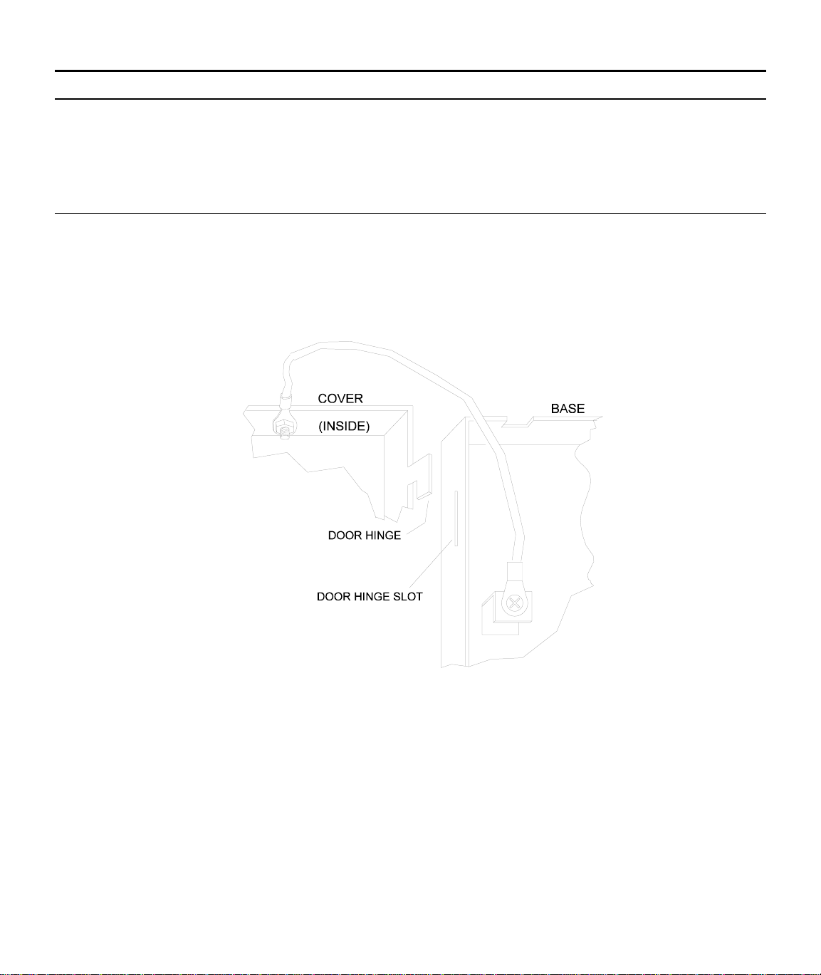
6.1 Grounding the 5129 Cover
Before connecting power to the 5129, connect the earth ground wire to the base and cover. Make sure that the
ring lugs are oriented properly. Figure 6.1-A shows the proper connection and orientation.
After the 5129’s cover and base are attached, make a slight bend to the wire that is attached to the cover. This
keeps the wire from getting caught between the cover and base when the cover is closed.
Figure 6.1-A: Connecting the Ground Wire
10
7. Channel (Zone) Operation and Wiring
The 5128/29 features four fully supervised channel (zone) inputs. They can be programmed to accept three
types of inputs. Contact closure, active high voltage input, or active low voltage input.
CHANNEL 1 (ZONE 1): FIRE ALARM
CHANNEL 2 (ZONE 2): FIRE TROUBLE
CHANNEL 3 (ZONE 3): SPRINKLER SUPERVISORY
CHANNEL 4 (ZONE 4): UNDEFINED ALARM
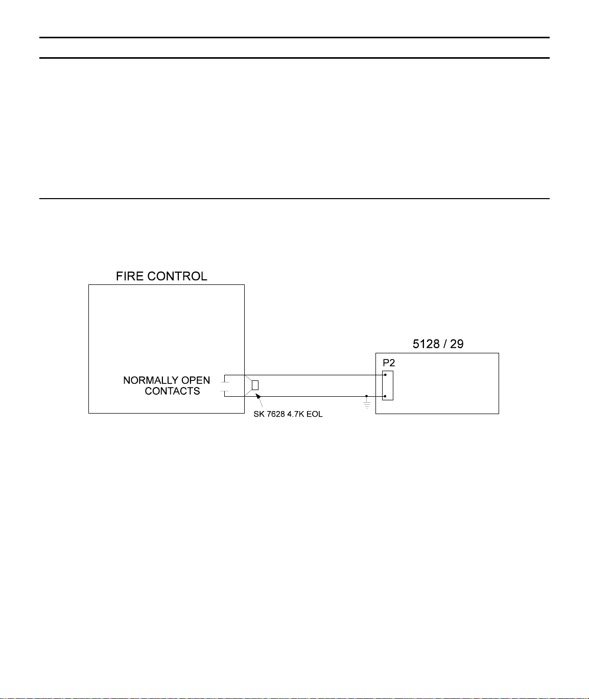
7.1 Dry Contact
A short across the end-of-line resistor (EOL) causes an active channel (zone). An open loop causes a trouble
condition.
Figure 7.1-A: Contact Closure
11
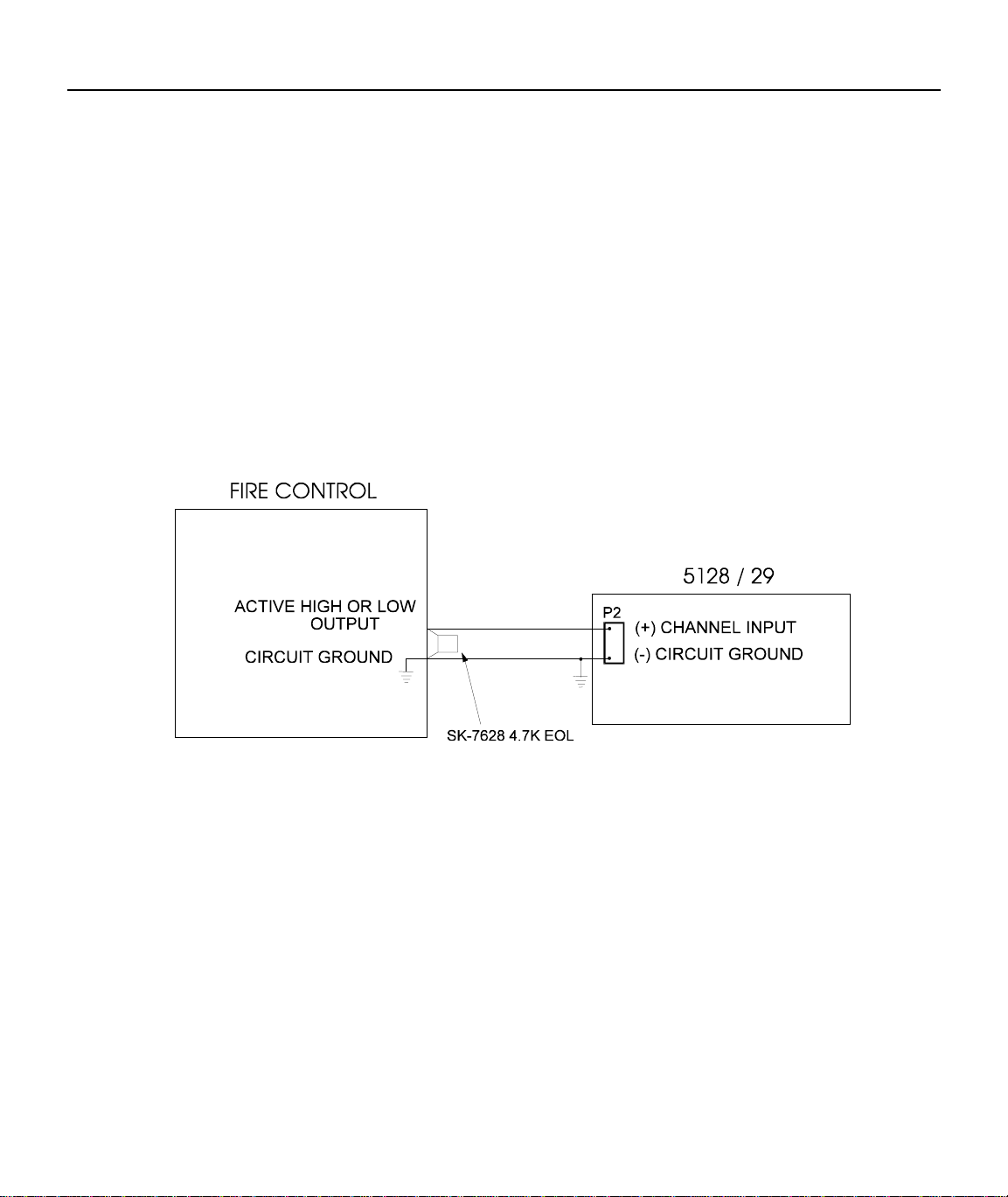
7.2 Voltage Input (Active High or Active Low)
This diagram shows how to wire the 5128/29 for voltage input. The input must be from a compatible UL listed
control panel.
Active High
A short across the EOL or an open loop causes a trouble condition. Pulling the input high (10 to 30 VDC)
causes an active channel (zone). (At the time of this manual’s printing, the Cerberus Pyrotronics System 3 with
CSI-35 is the only UL Listed model available.)
Active Low
A short across the EOL or pulling the input low causes an active channel (zone). An open loop causes a trouble
condition. (This information is provided for the future. At the time this manual was printed, no compatible UL
listed control panel with an active low input is available.)
Figure 7.2-A: Active High or Active Low Voltage Input

12
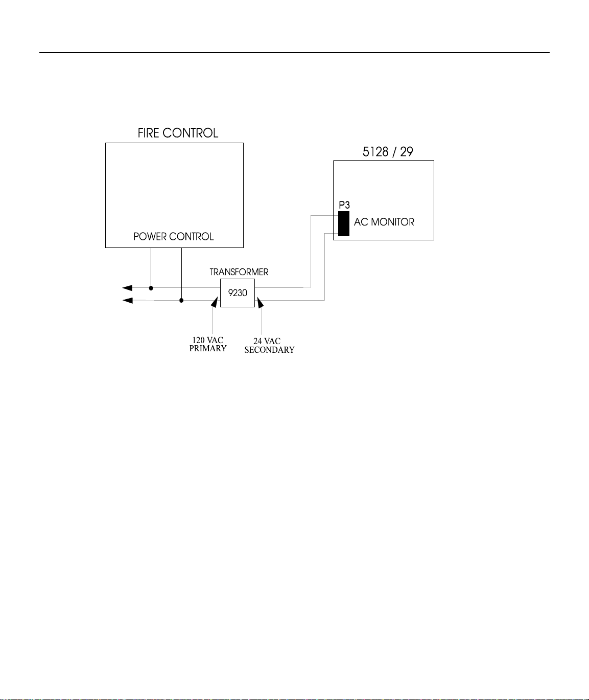
8. AC Monitoring Operation and Wiring
The 5128/29 features an AC monitoring circuit. The communicator will report AC trouble when AC has been
below 85 percent of nominal for a programmed amount of time (0 or 6-15 hours). AC can be monitored directly
using a model 9230 step down transformer (see Section 8.3). AC monitoring can also be performed with a dry
contact (active low) (see Section 8.2) or an active high voltage input (see Section 8.1).
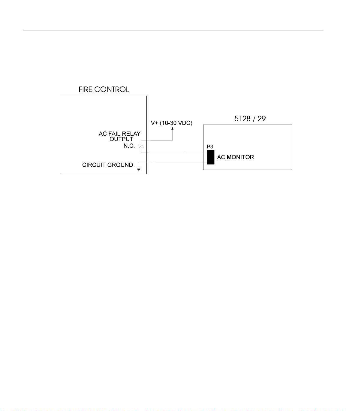
8.1 Voltage Input—Active High
If the fire control panel has an active high AC trouble voltage output (10 to 30 VDC), attach this output directly
to the AC monitor input on the 5128/29. (At the time of this manual’s printing, the Cerberus Pyrotronics
System 3 with CSI-35 is the only UL Listed model available.)
Figure 8.1-A: Active High Input
13
8.2 Dry Contact
If the fire control panel monitors its AC input and has a contact closure AC trouble output, apply 10 to 30 VDC
to the AC monitor input of the 5128/29 through the normally closed contacts. Select “ACTIVE LOW” in
programming for this configuration.
Figure 8.2-A: Dry Contact Input
14
8.3 Monitor AC
If the fire control panel does not have an AC trouble output, the model 9230 AC monitoring step down
transformer must be used to allow the 5128/29 to monitor the fire control panel’s 120 VAC power input. Wire
the secondary side of the transformer directly into the 5128/29 AC monitor input.
Figure 8.3-C: AC Monitoring Input

15
9. Relay Connection
The 5128/29 provides one relay output. You can connect the relay in normally open or normally closed
configurations or both. The relay contacts are rated at 1 A, 24 VDC/24 VAC. See Figure 9-A for relay contact
connections.
The relay can be used for either of the following:
• To activate for any alarm.
• To activate for system trouble conditions, loss of AC power, failure of the 5128/29 to communicate, and
phone line troubles.
Figure 9-A: Relay Connection

16
10. Telephone Line Connection
To meet NFPA 72 Central Station Fire Protective Signaling and Remote Signaling Systems, both telephone
lines must be installed. Connect the 5128/29 to the phone line using an RJ31X type phone jack as shown in
Figure 10-A. The telephone company will install an RJ31X jack upon request.
Figure 10-A: Telephone Wiring
17
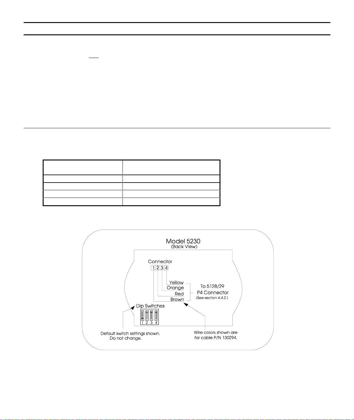
11. Model 5230 Remote Annunciator
The optional Model 5230 Remote Annunciator can be temporarily connected to the 5128/29 to program the
system. Note that only one 5230 can be used. If the 5230 is used, a cable, part number 130294, (ordered
separately), is also needed.
Model 5230 key functions are described in Section 12; programming instructions are in Section 15.
NOTE: At the time this manual was printed, the 5230 is the only available method for programming the
5128/29.
11.1 5230 Installation
The table below shows how to make the connections. Figure 11.1-A below shows the location of the 5230
terminal block.
5230 TERMINALS CABLE WIRE COLORS
(P/N 130294)
1 GROUND BROWN
2 POWER RED
3 INPUT ORANGE
4 OUTPUT YELLOW
Figure 11.1-A: Model 5230 Back View

18
11.2 Display
The 5230 is equipped with an LCD (liquid crystal display) that displays English-language messages. If the
5128/29 is not being programmed, the LCD cycles through all messages that are applicable at the time, showing
a different one every 1.5 seconds. The messages are listed in the troubleshooting section of this manual
(Section 17).
Figure 11.2-A: Model 5230 Remote Annunciator (Front)
11.3 Power LED Indicator
When DC power is being supplied, the POWER LED glows steadily. If DC power is not being supplied, the
POWER LED is off.
11.4 Buzzer
An audio transducer buzzer is built into the 5230 annunciator. It produces short beeps to annunciate keystrokes.
It also emits a long, high-pitched tone to indicate a trouble condition or when an annunciator function has been
entered incorrectly.
19
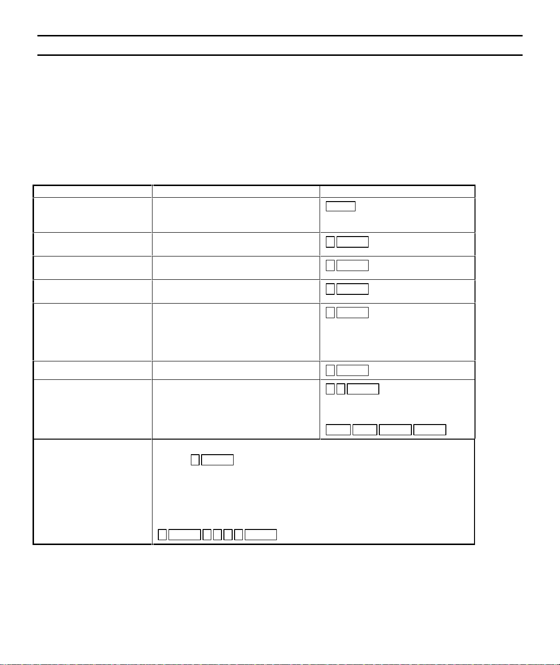
12. Key Functions
The 5230 annunciator function keys are described below. The remaining keys are used only for entering digits.
Code 0 refers to the installer’s code (factory programmed as “5128”). Code 1 refers to the operator’s code
(factory programmed as “1111”). These two codes are described in Section 15, steps 11 and 12. Table 12-I
explains each function and summarizes the keystrokes.
NOTE: The message, “TRY AGAIN”, appears if you do not press any keys for five seconds while accessing a
function, or, if you attempt to access a function before exiting from another function.
TABLE 12-I: Key Functions
FUNCTION NAME EXPLANATION KEYSTROKES
CLEAR Corrects mistakes. If you enter a
function incorrectly, the 5230 will emit
a long, high-pitched tone.
CLEAR
SYSTEM TEST Tests the communicator by sending a
test report to the central station. 0 ENTER Code
CLEAR ALARM
MEMORY Clears all data from the alarm memory. 2 ENTER Code
RESET DIALER Aborts an in-progress call to the central
station. 3 ENTER Code
DISPLAY ALARM
MEMORY Displays events currently saved in the
alarm memory.
(NOTE: It is recommended that you
clear the alarm memory after you
display it.)
5 ENTER Code
DISPLAY TROUBLES Displays trouble conditions. 6 ENTER Code
ENTER PROGRAMMING
MODE Enters the special programming mode
that allows you to change programmable
options.
2 7 ENTER Code
To exit programming mode, press
STEP STEP CLEAR CLEAR
SET TIME To set the time:
1. Press 9 ENTER
2. Enter Code 0. The SET MODE LED will turn on.
3. Enter the time in 24-hour military format (include leading zeros).
EXAMPLE:
To enter SET TIME mode and set the time for 3:30 PM, the keystrokes are:
9 ENTER 1 5 3 0 ENTER .

20
12.1 Operating Modes
OPERATING MODE: ALLOWED DURING
ALARM: CODE REQUIRED:
0 System test NO Installer’s or Operator’s
2 Clear alarm memory NO Installer’s or Operator’s
3 Dialer reset YES Installer’s
5 Display alarm memory NO Installer’s or Operator’s
6 Display troubles NO Installer’s or Operator’s
9 Set time NO Installer’s or Operator’s
25 Troubleshooting NO Installer’s
27 Program NO Installer’s
13. Preprogrammed EEPROMS (electrically erasable read-only memory)
The Model 5128/29 provides a wide variety of features that can be selected for use depending on your needs.
These features are programmed into an EEPROM (Electrically Erasable Programmable Read-Only Memory)
chip. For descriptions of the options, see Section 15.
The 5128/29 is shipped with a factory-programmed EEPROM. The options that have been programmed are
shown in the step programming form in Section 15.
Changing the Options
To customize the features to suit a particular installation, you can reprogram the options stored on the
EEPROM using the Model 5230 Remote Annunciator. The EEPROM is an 8-pin integrated circuit chip that
can be reprogrammed up to 1,000 times. For instructions on reprogramming the options, refer to Sections 14.1
through 15.
14. Step Programming5230 Annunciator
This section describes the STEP PROGRAMMING mode (mode 27), using the 5230 Remote Annunciator. The
basic operation of the 5230 is discussed in Section 14.1. The step programming procedure is explained in
Section 15. (The temporary annunciator is connected at P4.)
IMPORTANT:
Connector P4 is used for temporary annunciator installation only.
Other manuals for 5128
1
This manual suits for next models
1
Table of contents
Other SILENT KNIGHT Cell Phone manuals


