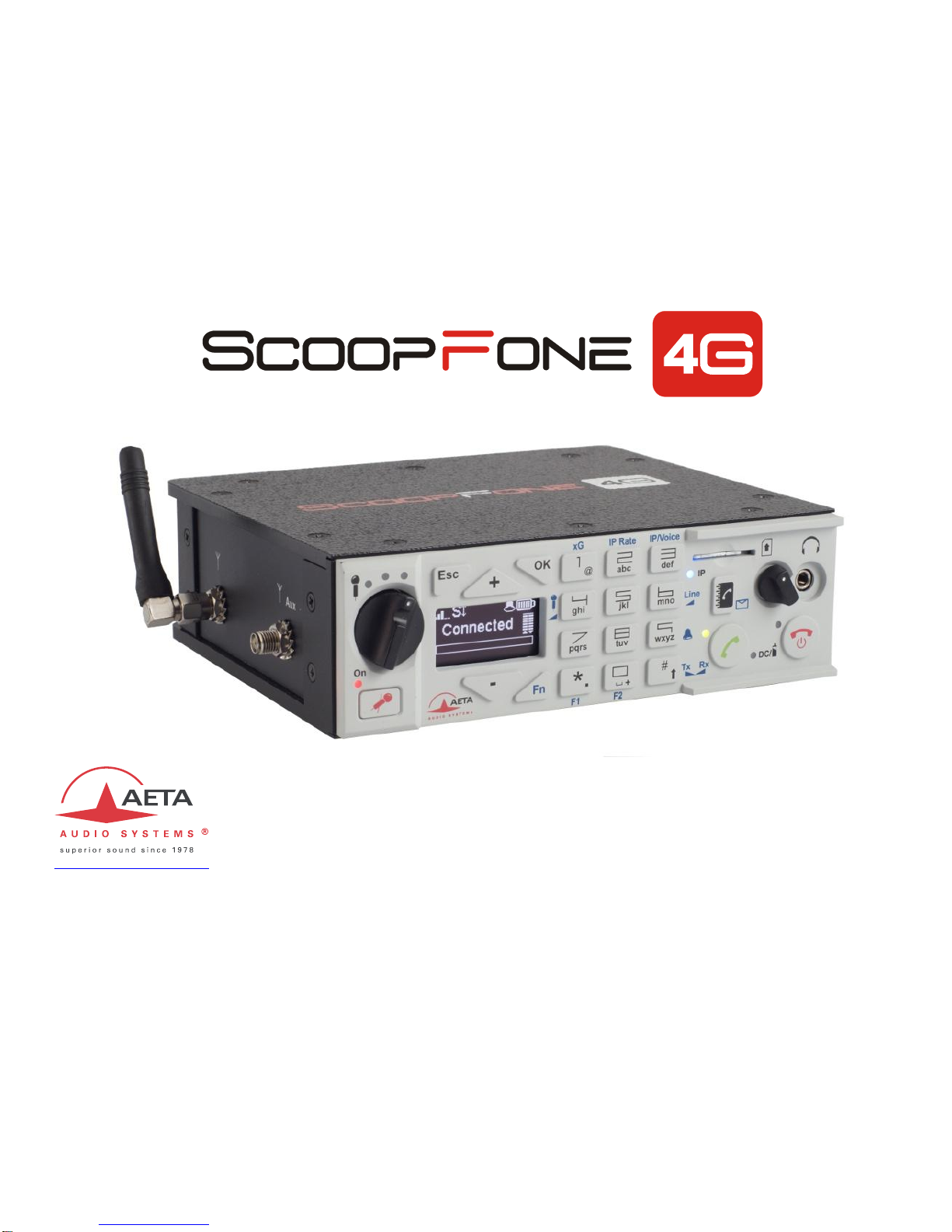
Aeta Audio Systems ScoopFone 4G User manual
Specifications are subject to change without notice
55 000 095-H © 2018
Getting started
www.aeta-audio.com

2
Front panel & controls
1
23
4
5
6
7
810
11 1314
15
16
17 18
19 20 21
24
12
922
23
1. Microphone potentiometer: controls the microphone level.
2. Microphone indicator: This red LED turns on when the
microphone input is enabled.
3. Microphone button: Enables/mutes the microphone input.
4. Microphone level: 3-segment indicator
(-20 dBFS / -12 dBFS / -3 dBFS).
5. OLED display
6. Navigation keys: Use the Esc key to access the configuration
menu. Use the Up/+ and Down/- keys to browse the selections
and use the OK key to validate menu selections or messages.
7. Function key: Used in combination with other keys, it gives
access to functions marked in blue. It is active for 5 seconds. This
key is called Fn hereafter.
8. Change Radio Access Technology: When Fn is enabled, use
this key to access the type of mobile network (Auto, 3G, 4G).
9. Microphone gain: When Fn is enabled, press this key 4and use
+key to increase and - key to decrease the gain of the
microphone.
10. IP Rate: While an AoIP link is active, press Fn, press this key and
use +key to increase and –key to decrease the bit rate.
11. Line input level: When Fn is enabled, press this key and use the
+and –keys to increase/decrease the line input gain; the
maximum (clipping) level of the input (from +4 dBu to +16 dBu) is
displayed during the adjustment.
12. IP / Voice: When Fn is enabled, use this key to switch between
the voice mode and the IP mode.
13. Shift/Balance: Switches the keypad to alphanumeric or numeric
mode. When Fn is enabled, press this key and use + and –to
adjust the send/receive balance for the headphone monitoring.
14. Ringer shortcut: When Fn is enabled, use this key to enable or
disable the ringer.
15. Network mode indicator: This blue LED turns on when the IP
mode is selected for outgoing calls.
16. Communication indicator: This green LED turns on when the
communication is established.
17. Phonebook: Press the Phonebook key to access one of the 9
memories or to save the current phone number into a memory.
Or, while in Fn mode, access the received SMS.
18. SIM Card slot
19. Call key: Use the Green phone key to initiate a call.
20. Power indicator: The LED turns red when the battery is charging
from an external power supply and green when it is fully charged.
21. Alarm indicator: The red LED turns on when an alarm triggers
(PIN request, missing SIM, no network, sync loss…). The nature of
the alarm is shown on the display.
22. Hang up key:Press the Red phone key to release a connection.
Hold it for 2 seconds to start or switch off the ScoopFone 4G.
23. Headphone volume: Handles the level of the headphone
connected on the ScoopFone 4G
24. Headphone jack: 3.5 mm stereo jack.
3
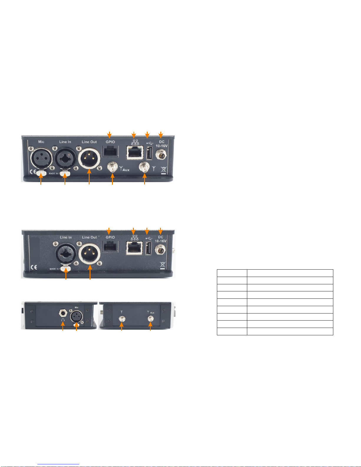
Rackmount version (ScoopFone 4G-R)
124
35
6 7 8 9
Portable version (ScoopFone 4G)
45
6 7 8 9
10 12
3
1. Main antenna: SMA socket
2. Aux antenna: SMA connector for the second antenna
(“diversity” mode)
3. Microphone input: balanced input, gain switchable from 0
to 48 dB by 16 dB steps.
4. Line input: combo socket, balanced input (XLR),
unbalanced input (6.35 mm jack), +16 dBu max.
5. Line output: balanced output, 3 -pin XLR. Level adjustment
via menu from +4 dBu to +22 dBu.
6. GPIO: RJ45 socket with 2 relays, 2 contacts and LPS power.
(cable less than 1 m long).
7. Ethernet: 10/100Mbit/s Ethernet interface
8. USB A: USB 2.0 Interface for memory import.
9. DC Power: 2.1 mm jack for external LPS DC power 10 to
16 V, 1.5 A max. Can also be used for charging the
batteries.
10. Headphone: 6.35 mm jack (only on portable version).
GPIO Interface
Contact
Function
1
+5 V / 500 mA
2
Contact 1
3
Contact 2
4
Contact common 1&2
5
Ground
6
Relay 1
7
Relay 2
8
Relay common 1&2

4
Main screen
1 2 3 456
7
8
9
10 11
1. Network level indicator: 5-bar display.
2. Function key indicator:flashing when functions marked in blue
are enabled by the Fn key.
3. SMS reception indicator: stays on until all the new SMS are read,
using Fn and Phonebook keys.
4. Microphone power indicator: 48V phantom.
5. Buzzer indicator
6. Battery level (portable version): 5-segment display
7. Mobile network operator name, current network
8. Audio send level: From -30 dBFS to 0 dBFS.
9. Data connection active.
10. SIP registration active: on when the unit is registered on a SIP
server
11. Transmission quality: 6-segment indicators, showing respectively
the quality of the transmission and reception on the network
INTRODUCTION
We advise you to read this guide first to help you get familiar
with the ScoopFone 4G in a short time. For more detailed
information, please consult the full user manual on our web
site:
www.aeta-audio.com
For this guide, we assume that the basic principles are known
and that you have already connected a microphone and a
headphone to the unit.
The ScoopFone 4G allows you to set up live mono audio
connections in three possible ways:
Standard telephone or “HD Voice” (7 kHz wide band)
link over mobile 2G or 3G networks.
Audio over IP (AoIP) connections over mobile 3G or 4G
(LTE) networks.
Audio over IP (AoIP) connections over an Ethernet wired
access.
In IP mode, up to 20 kHz bandwidth is available with the
OPUS algorithm (default algorithm). In case the remote unit
does not support this algorithm, the connection will be
established automatically with G722 or G711 coding.
AoIP connections are normally based on the SIP protocol. It is
possible to use a “Direct RTP” mode without the SIP protocol:
for such operation please refer to the detailed user manual.
This guide applies to units with firmware version 1.09 or newer.
5
SET UP
ScoopFone 4G can be operated under an ambient temperature of 0°
to 45° C (32°F to 113°F).
Installation in a 19” rack (ScoopFone 4G-R)
If needed, a rack mount tray is available for integrating one to three
ScoopFone HD-R or ScoopFone 4G-R units into a 1U space of a rack.
Powering
Before switching on the ScoopFone 4G, you need to have 6 AA
batteries inserted in the bottom compartment, or an external DC
power supply connected via the DC jack.
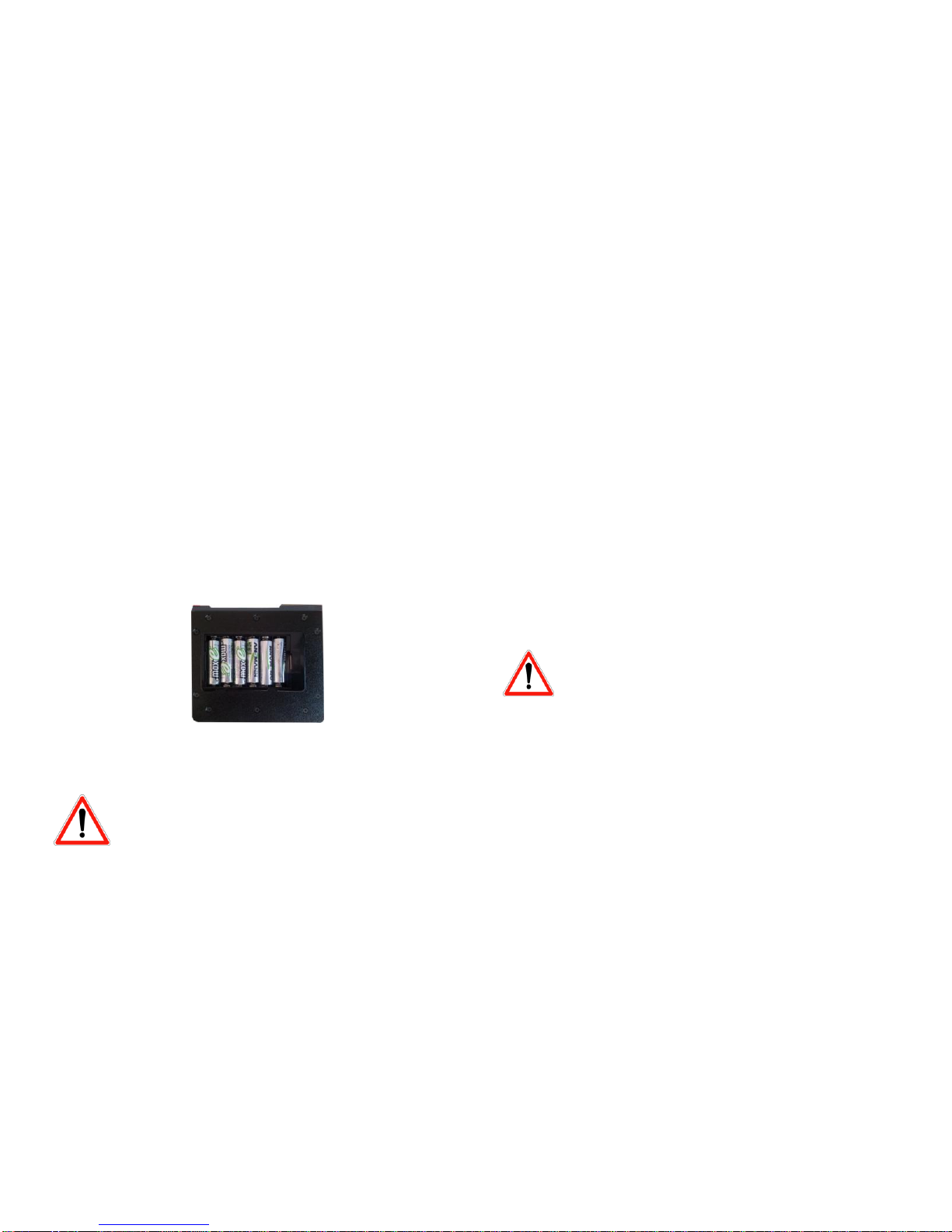
Batteries (Portable version only)
ScoopFone 4G works with NiMH batteries. Six 2500 mA.h NiMH
batteries provide power for more than 5 hours of transmission.
In order to get an accurate charge level indication with rechargeable
batteries, it is necessary, at least once, to leave the ScoopFone 4G on
with the external DC power until it is fully charged.
CAUTION: THERE IS RISK OF EXPLOSION IF THE
BATTERIES ARE OF A WRONG TYPE, OR ARE
INSERTED THE WRONG WAY.
DISPOSE OF USED BATTERIES ACCORDING TO
INSTRUCTIONS.
External power supply (indoor use)
The external DC supply is also used to charge the batteries. Only
NiMH batteries are supported by the internal charger. You can use
the provided LPS power adapter (GS25B12 or GST25B12), or another
adequate LPS DC power source. ScoopFone 4G runs from a nominal
12 V, but it can run with a voltage from 10 to 16 V, with a maximum
consumption of 1.5 A.
Antennas
The ScoopFone 4G uses female SMA sockets. You must connect at
least one antenna on the rear panel. A second antenna is
recommended to optimize the mobile operation. For the best
efficiency, place the antennas as far as possible from each other.
SIM card
To establish mobile links, you should have a SIM card from a mobile
telecom operator. ScoopFone 4G accepts standard size SIM cards;
use a card adaptor if necessary for supporting a micro-SIM or nano-
SIM card (Contact your dealer for more details).
Switch off the unit before inserting the SIM card
To insert the SIM card into the slot, follow the orientation marked
on the front panel (contacts facing down, cut mark forward). As the
SIM card holder is a push-push holder, you should push the SIM card
as well to extract it.
Warning: for a new SIM card requiring activation (e.g. prepaid SIM
card), you can use a mobile phone to perform the activation
procedure.
You can do the same for disabling the call waiting tone
(recommended for avoiding undesired tones during a report)
6
MAKING A CALL
Switching ScoopFone 4G on / off
To switch the ScoopFone 4G on, press for 2 seconds.
To turn it off, press for 2 s; a confirmation message is
displayed. Press OK to confirm or Esc to cancel.
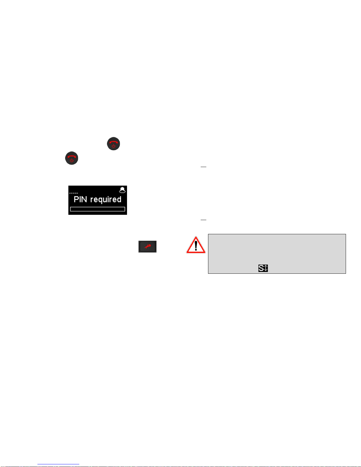
Enter the PIN code
If the PIN code is enabled on your SIM card, you must enter it and
validate with OK.The PIN code can be saved using the menu.
Adjust the microphone level
Turn ON the mute LED indicator, using the mute key if
needed.
Set the Potentiometer ([1] on page 2) to its middle position (white
dot of the button in the topmost position). Adjust the headphone
balance (send/receive): enable the Fn mode and press the #key,
then set the balance to the average position with the +and –keys.
Make a test with your microphone while watching the level
indicators (above the potentiometer). If the level is too high or too
low, enable Fn mode + key 4and press key +to increase or key -to
decrease the gain of the microphone, until you get the appropriate
level.
From then on, you can use the potentiometer for fine adjustment.
Preparation: for Ethernet network (IP mode)
Connect the Ethernet Interface ([7] on page 3) of the ScoopFone 4G
to the network. If the automatic network switch is disabled, you
should select the Ethernet network through the IP / IP interface
menu.
The blue “IP” LED shows the type of outgoing call that can be set up:
LED on for the IP mode. If necessary, activate this mode using the
shortcut Fn + 3 (IP/Voice).
Preparation: for IP mode over a mobile network
If you have “Ethernet”displayed, disconnect the Ethernet cable from
the ScoopFone 4G, or force the selection of the mobile network
using the menu IP / IP interface.
The blue “IP” LED shows the type of outgoing call that can be set up:
LED on for the IP mode. If necessary, activate this mode using the
shortcut Fn + 3 (IP/Voice).
For links over the Internet via an access router with NAT,
we recommend using a STUN server. To enable it, enter
the IP / Use STUN menu.
If you use your ScoopFone 4G in IP mode with a SIP server,
you should have the icon displayed on the screen.
Preparation: for IP mode over a mobile network
Receiving mobile phone calls is always possible regardless of the
current mode; no specific setting is needed for receiving this type of
calls.
However, before setting a call in mobile voice mode, you should first
activate outgoing voice calls, using the shortcut Fn + 3 (IP/Voice).
The blue “IP” LED must be off.
7
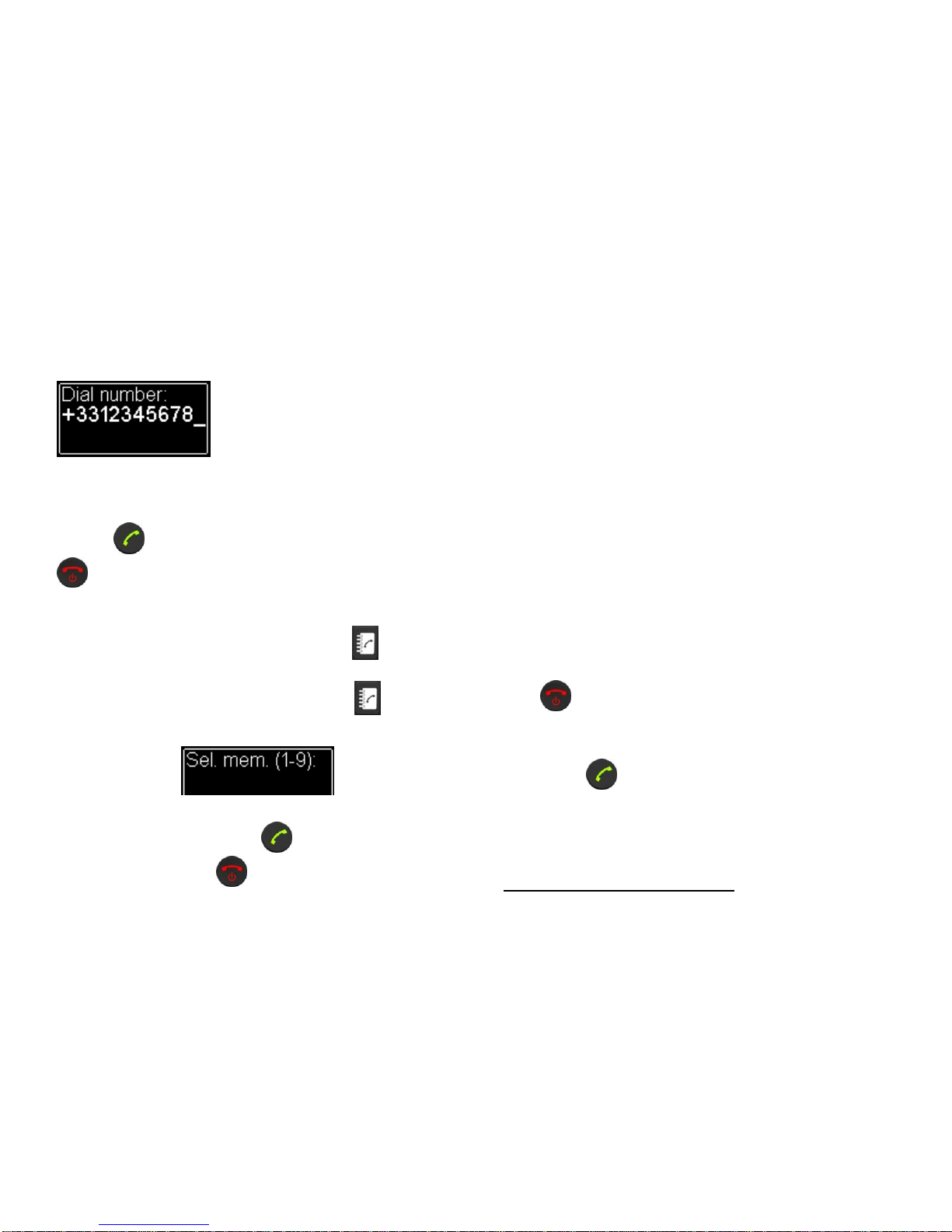
Making a call
Enter directly with the keypad the call destination: phone number, IP
address, or SIP identifier (URI).
Press UP or DOWN to erase the last digit(s)/character(s).
Press the 0key twice to get the international +symbol.
If needed, press the #key to access the alphabetic characters.
Press the key to make the call. Otherwise cancel using Esc or
.
Using the phonebook
Enter a number as described above, and press the key to save
this number into one of the 9 memories of the current mode.
To recall a number from the phonebook, press the key and
enter the number of the desired memory from 1 to 9.
The number is displayed and you can:
Set the call by pressing the key.
Cancel using Esc or .
Edit the number using +or –
During the call
To adjust the headphone balance, enable the Fn mode and press the
#key. Adjust the balance as desired using the +and –keys.
Adjust the transmission bit rate in IP mode
You can adjust the transmission bit rate during an audio
connection1. Enable the Fn mode + 2 (IP Rate) key. Using the Up and
Down keys you can increase or decrease the bit rate.
Notes:
The quality bars on the screen (see [11] on page 4) provide
real time information on the transmission quality for both
directions (but for the transmit direction, this depends on
the remote unit’s capability).
If the connection is set with an AETA product at the other
end, the bit rate also changes in the receiving direction, from
the remote codec.
Hang up
Press twice to hang up.
Redial
Press the key twice to redial the last called number.
1If the link is set with the Opus coding algorithm.

8
How to get an HD Voice connection
To get an HD Voice connection, some conditions must be met:
Both devices involved in the connection must support HD
voice.
HD voice must be supported by the mobile network.
Usually, both units should be connected on the same mobile
network (same carrier).
Most often, 2G networks do not support HD voice. This
depends on the country or area, and the network carrier.
For this last reason, the radio technology indication (2G, 3G, 4G
display on the screen) is a useful indication that HD Voice is possible.
In addition, it is possible to force the operation to 3G mode via the
menu Mobile / Mobile network. You also have a shortcut with Fn +
1 (xG).
How to turn on/off the ringer
Enable Fn mode and press 9 key to change the ringer state.
When the ringer is off, the ringer icon on the display shows muted.
Reading SMS
Enable Fn mode and press the key to show the list of the
received SMS.
If you have got several, press OK to read the selected SMS. Press the
Esc key to keep it, otherwise OK to delete it.
IMPORTING MEMORIES
You can import a phonebook into the ScoopFone 4G using a
USB memory stick.
To do this, place a "book-scoopfone.txt" import file on the
root of the USB drive and plug it into the ScoopFone 4G after
it has started.
The import file must have the following format:
Memory number: type of memory, phone number or SIP URI
Memory number : 1 to 9
Type of memory : 0 for voice , 1 for IP
Example:
1:0,0141361268
2:0,0141361279
1:1,30000
2:1,[email protected]-audio.com
Note: importing a file completely clears the previous
phonebook; all the memories are reconfigured or erased.
.
9
MENU
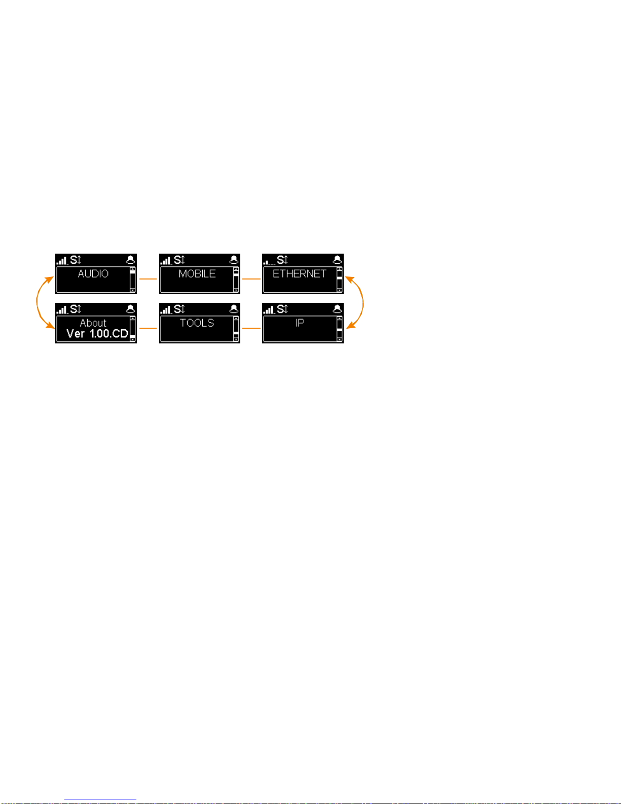
First menu level
Audio: menu for configuring the audio interfaces
Mobile: configuration of the internal mobile access module
Ethernet: configuration of the Ethernet interface
IP: configuration of the IP transmission mode
Tools: user interface configuration, reset settings
About: shows information on the ScoopFone 4G such as:
Firmware version number
SIM card phone number
SIP account and server address
Ethernet interface IP address
Reference of the internal radio module
10
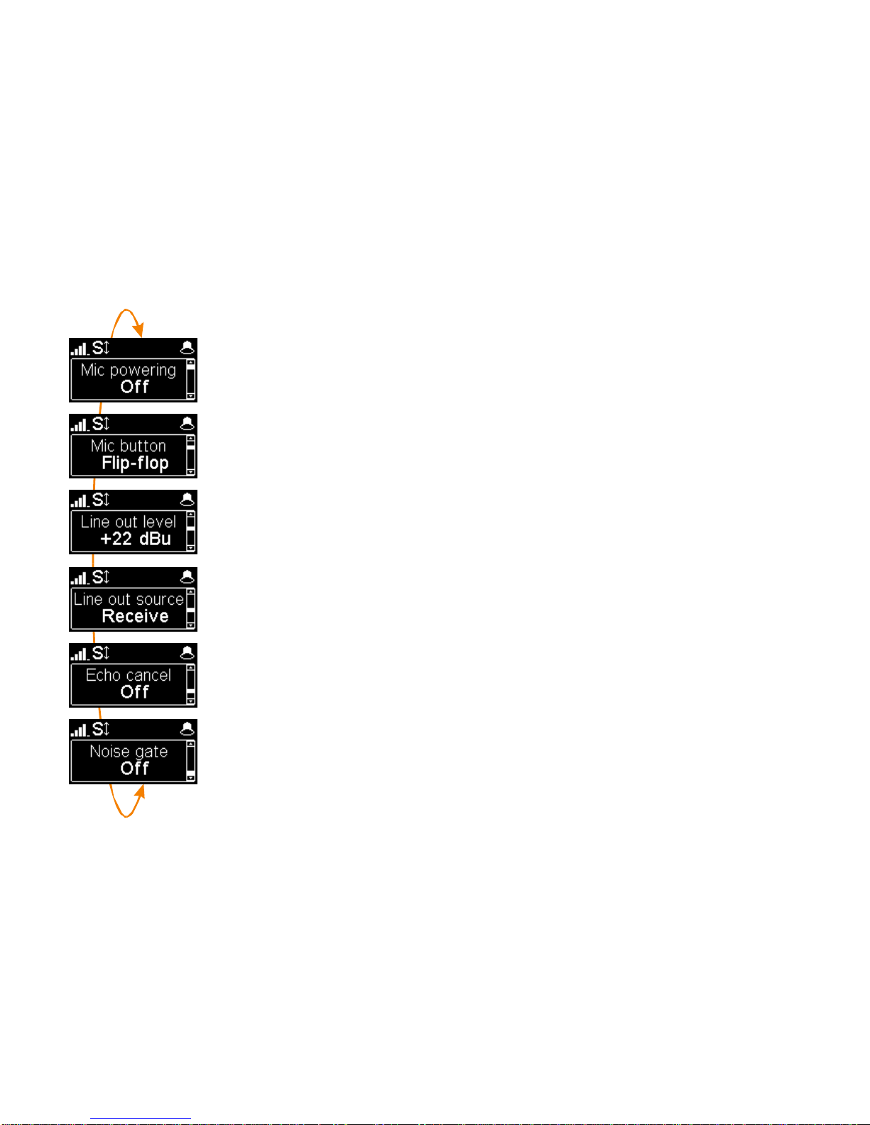
AUDIO MENU
Microphone phantom power
You can enable 48 V phantom power
Selection of microphone button operation
Flip-flop : switch the input between enabled and disabled
Push to talk : keep the key pressed to enable the microphone input
Cough key : keep the key pressed to mute the microphone input
Line output level adjustment
The maximum output level can be set from +4 dBu to +22 dBu.
Line output source selection
You can select between the transmit signal (Send), the received signal (Receive) and the
headphone balance (Balance).
Echo cancellation
You can enable local echo cancellation.
Note : this echo cancellation is active only for the mobile VOICE mode
Noise gate
You can enable background noise suppression on the sent signal.
Note : this function is active only for the mobile VOICE mode

11
MOBILE MENU
Set the mobile Radio Access Technology
You can force the mobile on a specific radio technology: 2G, 3G, 4G, or just let the mobile module
select the best available network by using the Auto mode (recommended).
It is also possible to force the selection of the mobile operator, by using an extended menu. See below how to
activate this menu.
Enable mobile data transmission
You can disable mobile data transmission via the mobile network.
Note : this does not affect the IP data transmission over the Ethernet interface
Set the mobile operator APN
The ScoopFone 4G features a preset APN for each operator. You can enter another one if this
preset is not suitable, or if the operator is not included in the internal list of presets.
Note: to reload the APN from the internal list, you should erase the current one and then restart
the unit.
Line quality setting
This setting adapts the size of the reception jitter buffer depending on the expected transmission quality (the
lower quality, the bigger buffer for compensation).
“Low” is recommended for a mobile data link. The “Very high” setting provides the minimum latency, but is also
more sensitive to possible jitter on the network.
Extended menu:
There is a menu, reserved for advanced users, that also allows selecting manually the mobile network you want to connect to.
To activate this extended menu:
-Switch to IP mode if necessary (Fn key, then IP/Voice)
-Hit the following key sequence: 1 Up # # @ A E T A @ (display : @AETA@)
-Validate with the call key
From then on, the extended menu is accessible until the ScoopFone 4G is switched off.
12
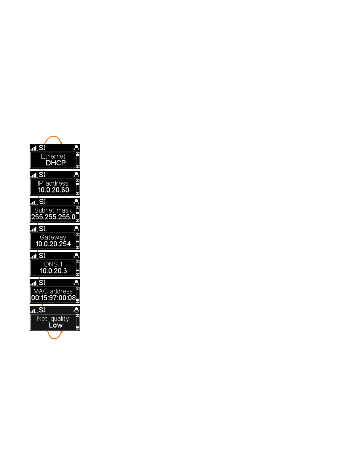
ETHERNET MENU
Note : changes made by using this menu are only effective after exiting the menu ( Esc key to go back to the upper level).
Set Ethernet IP address allocation
Select DHCP on a network equipped with a DHCP server, otherwise select MANUAL to set a static IP
address.
IP Address
For static IP addressing, enter here the IP address.
Set network mask
For static IP addressing, set/change here the network mask
Set Ethernet gateway
For static IP addressing, set/change here the default gateway address.
Set DNS 1
For static IP addressing, set/change here the numeric address of the domain name server.
Display the Ethernet MAC address
Line quality setting
This setting adapts the size of the reception jitter buffer depending on the expected transmission quality (the
lower quality, the bigger buffer for compensation).
The “Very high” setting provides the minimum latency, but is also more sensitive to possible jitter on the network.

13
IP MENU
Note : changes made by using this menu are only effective after exiting the menu ( Esc key to go back to the upper level).
IP interface selection
With this menu, you can force the Ethernet or the mobile data network for outgoing call in IP mode. In Auto mode,
the IP interface switches to Ethernet when an Ethernet cable is connected. Conversely, whenever the Ethernet
cable is disconnected, the ScoopFone 4G switches to the mobile data network.
Set the default IP transmission bit rate (OPUS)
Here you can set the preferred bit rate for the OPUS coding, from 12 kbit/s to 192 kbit/s.
Note: this is the initial bit rate, when the link is established; afterwards the bit rate can be changed during the
transmission if the connection is done with OPUS.
Enable STUN
Using STUN is usually recommended when using a SIP server; however this is not suitable in some cases.
As a general rule, enable STUN. If you meet connectivity issues (such as failure to sync when starting the
connection, or link loss after a few seconds), disable the function.
Type of NAT (Network Address Translation)
When STUN is used, the ScoopFone 4G can detect the type of NAT performed by the router through which it
accesses the Internet. In case the router applies symmetric NAT, it is usually recommended to disable STUN.
Display the public IP address
When STUN is used, the ScoopFone 4G can detect the public IP address, with which it accesses the Internet.
Default AoIP protocol
AoIP connections normally use the SIP protocol. By selecting here “Direct RTP” it is possible to make calls without
the SIP protocol. The various parameters of this “Direct RTP” mode are available only via the embedded html
pages. The operation mode is described in the detailed user manual.

14
Change displayed SIP name
You can enter a name that will be displayed on the remote unit (depending on its type and settings).
Display your SIP account number
The SIP account data are normally entered/edited by using the web interface of the ScoopFone 4G.
Server SIP port
The default SIP port for the server is 5060. In some cases it is useful to use the alternate port 5070.
You can also set any other port value by using the web interface, or the extended IP menu (see below)
RTP port for the audio stream (display only)
This port can be changed through the web pages or the extended IP menu (see below).
Activate packet duplication (double stream)
When this feature is enabled, a double stream is sent, for a more robust transmission.
Extended menu:
Some parameters of the Audio over IP (AoIP) operation are not normally accessible via the IP menu, or they can only be read but not edited.
However, there is a mode, reserved for advanced users, that provides full access to all the AoIP parameters.
To activate this extended menu:
-Switch to IP mode if necessary (Fn key, then IP/Voice)
-Hit the following key sequence: 1 Up # # @ A E T A @ (display : @AETA@)
-Validate with the call key
From then on, the extended menu is accessible until the ScoopFone 4G is switched off.

15
TOOLS MENU
Save PIN in the ScoopFone 4G
If you select “On”, the PIN code is saved into the ScoopFone 4G and you need not enter it again
every time the unit is switched on (as long as the same SIM card stays inside the unit). If the
recorded PIN is invalid (e.g. after inserting another SIM card), the saved PIN is deleted and the
function is cancelled.
Automatic or manual answer
You can specify the number of rings before automatically answering calls, or select manual
answering.
Incoming call filtering
With “White list”, only the telephone calls (mobile voice) from numbers included in the
phonebook are accepted.
Note : this feature is available only on the rack mount version ScoopFone 4G-R
Auto redial
“On” activates the auto redial feature. In such case, when the ScoopFone 4G calls a remote unit, it
automatically redials the number whenever the link is dropped unexpectedly. The parameters of
this function are available via the embedded html pages.
Caution: you must hang up from the ScoopFone 4G for releasing the link once and for all.
Enable DTMF
If enabled, DTMF tones can be sent during a mobile voice connection, by using the keypad
(numeric keys, * and #).

16
TOOLS MENU (continued)
Function: contact 1
Can be used to make a call with memory 1, or transmit an "Info 1" state.
Note : the contact can operate on a transition (Switch) or a pulse (Pulse) for calling/hanging up a
call.
Function: contact 2
Can be used to make a call with memory 2, or control the microphone input mute, or force 3G
mode, or force 4G mode, or force the Voice mode, or force the IP mode, or transmit an "Info 2"
state.
Note : the contact can operate on a transition (Switch) or a pulse (Pulse) in order to call/hang up a
call. Other assignments are sensitive to the contact state.
Function: relay 1
Relay 1 signals the connection state :
connected (closed), on hook/idle (open), call in progress (blinking open/closed),
or signals the received "Info 1" state.
Function: relay 2
Relay 2 provides a selectable status:
None, Ready, SIP ready, Ring, 3G, 4G, Voice mode, IP mode, or received "Info 2" state.
Display brightness adjustment
3 brightness levels are available: Low, Normal, High
Reset settings
Reload the factory SIP account
Reset all settings, including the SIP account data.
17
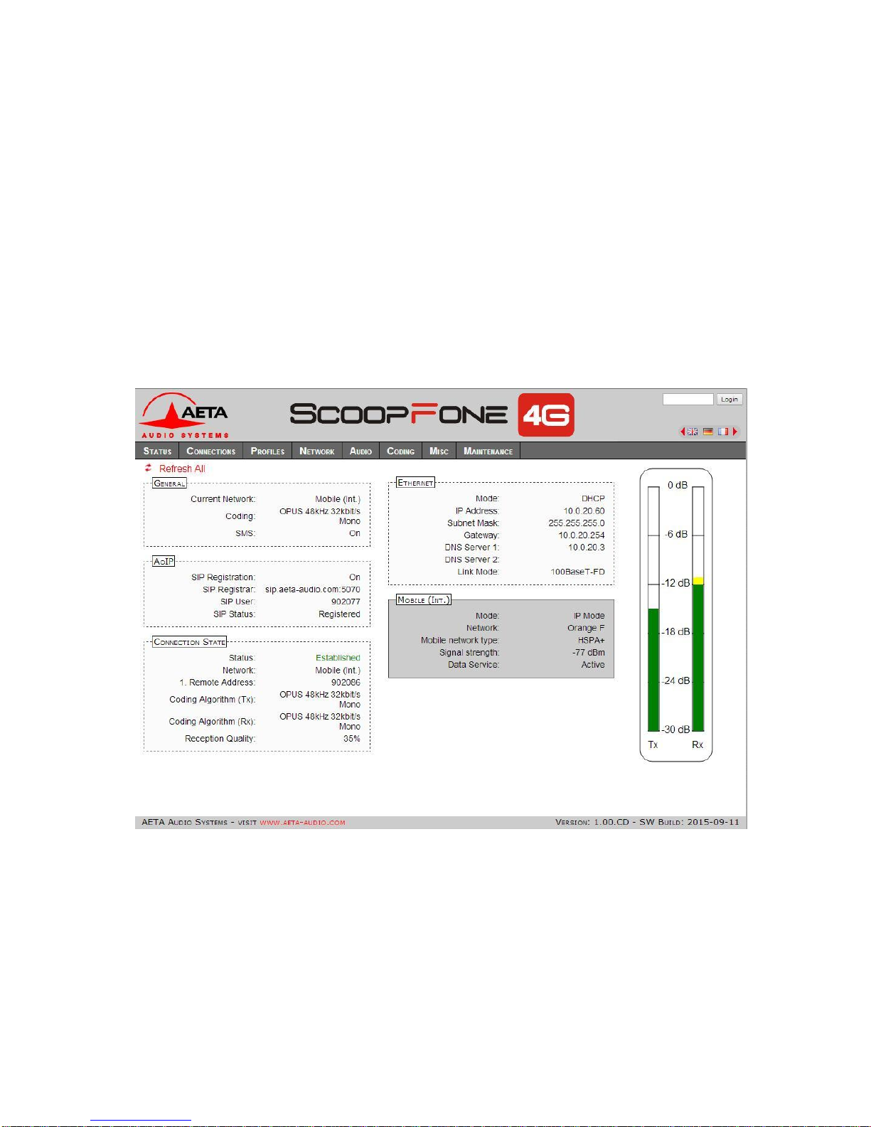
WEB INTERFACE
Once the ScoopFone 4G is connected on an IP network, the first step is to get its IP address, from the menu: About, or the
menu Ethernet / IP Address. On the control computer, launch an html browser and enter the IP address of the ScoopFone 4G
in the “address” or “URL” field. This gives access to the html server integrated in ScoopFone 4G, for extended status and control
features.

18
HOW TO …
Be ready to make mobile voice calls and receive AoIP
calls on the Ethernet IP link (recommended
configuration for the studio side).
Disable mobile data
Menu Mobile / mobile data : OFF
Avoid getting AoIP (Audio over IP) links
blocked/corrupted by mobile networks
Some operators require the subscription of a VoIP
option to allow streaming (RTP stream authorization)
Avoid unwanted voice calls
Select « White list » in the menu Tools / Incoming
calls. Only calls from numbers in the phonebook will
be accepted. This feature is only available on the
rackmount version.
Update the ScoopFone 4G firmware
Either from the html interface
Or with a USB key: menu Maintenance / System
update (beforehand, add the update file in the root
directory of the disk).
For more details, refer to the web page dedicated to
the ScoopFone 4G on our web site
www.aeta-audio.com.
Remote control the ScoopFone 4G (via Internet)
Refer to the application note "Using the AETA Remote
Access service"
TROUBLESHOOTING
The icon is not displayed while in Ethernet mode
Check that the Ethernet cable is connected
The icon is not displayed while in mobile IP mode
Check/correct the APN; if needed try to reload the
default APN (see Mobile menu)
The icon is not displayed
Change the «Server SIP port» (AETA server)
The icon is displayed, but the audio does not go
through, or stops after several seconds.
Enable or disable STUN
Change the RTP port
The audio stream is corrupted in mobile IP mode
Check whether a VoIP option is required by the
mobile operator
If the transmission quality bars are low :
oDecrease the network quality, Menu Mobile / Net
quality (affects the receive direction)
oEnable the packet duplication, Menu IP/Packet repl.
(affects the send direction)
You can’t change the bit rate during the connection
(shortcut Fn+2(IP/Rate))
This feature is only available with OPUS, so the
remote unit must support this codec.

19
AUDIO DIAGRAM
P48v
Off
Mic
power
Micro
HPF
50Hz Limiter
Level on display
Gain
0/16/32/48dB
Line
input
+
Line
Output
6.35mm
3.5mm
Mute
Volume
Volume
Networks
Volume
Volume
+
+

ACCESSORIES
AETA Test numbers *
IP : [email protected]
APN codes (France) *
ORANGE : orange-mib
BOUYGUES : b2bouygtel.com
SFR : sl2sfr
FREE : free
____________________________
____________________________
____________________________
Your numbers
____________________________
____________________________
____________________________
* Information valid at the date of issue of this document, and possibly depending on the
terms of the subscription to mobile data networks
Car battery adapter
Spare AC/DC adapter
Multiband Antenna
Carrying bag
Carrying bag with accessory pouch
www.aeta-audio.com
AETA AUDIO SYSTEMS S.A.S.
IMMEUBLE KEPLER 4 - PARC TECHNOLOGIQUE
18/22 AV. EDOUARD HERRIOT
92350 LE PLESSIS-ROBINSON –FRANCE
TEL. : + 33 141 361 200
FAX : + 33 141 361 269
Table of contents
Other Aeta Audio Systems Cell Phone manuals


