Silicon Laboratories LED PRO WF200 Owner's manual
Product specification
Name:WiFi Multi point Controller
Model:WF200
I. Product Summarize
1. Product constitute
2. Product summarize
LED-WiFi controller is following the traditional with infrared, RF technology controller foundation, it is birth
of market and customer's demand, it is one type controller which integration the newest wifi technical in the
market. It makes the LED control more convenience, more hommization. We can use an Android system or IOS
system mobile phone to install control software, then it can control LED, this is the wishes of every customer.
Use WiFi technology can make our control range more wider, can get rid of narrow space constraint, in
building can control more than 50m, in outdoor can control more than 100m.
II. Technical Parameters
1. Software technical parameters
1.Name: Magic Color 1.0
2.Runtime platform:Android version supportAndroid system(better one can support
Samsung, HTC), IOS version support IOS system, equipment must have WiFi function.
3.Language: English
4.Category: communications
5.Other:Free,,no plug-ins
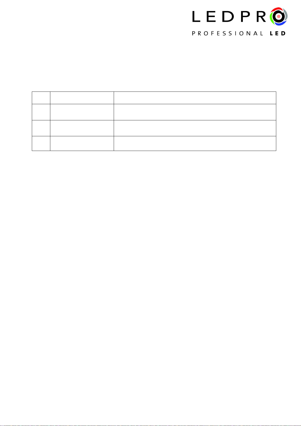
NO. Name Instruction
1 WF200 Controller It is the core of product, responsible for receive control signal and
control LED equipment.
2 disk Include IOS operating system and Android operating system
mobile soft.
3 manual Product use methods detailed instructions
1.Working voltage: DC5--24V
2.Working temperature:-20-60℃
3.Power consumption:<1W(12V)
4.Output::3 channel(common anode),4A/CH
5.Packing dimension:L215*W165*H55(mm)
6.External dimension:L107*W65*H30(mm)
7.Net weight:276g
8.Gross weight:320g
9.Receiving sensitivity: 802.11b DSSS(-5dBm),802.11b CCK (-10dBm),802.11g OFDM(-15dBm)
III. Dream Color 2.0 Instruction
1. Install Dream Color 2.0
First make sure your computer has been installed iTune, if not Please download the latest version of
iTunes,after complete the installation,in applications search "Dream Color 2.0", download and install.
2. Connect wifi controller
Connect wifi controller, open your phone connect wifi ,please make sure the wifi SSID for connection is:”
LN*** ”(LN001-LN016)。

3.2.2
Complete setting if pop-up the following window: indicates the connection succeeds
3.2.3
Otherwise the tip:
3.2.4
3.Connect wifi controller
Click on the SETUP button and enter SETUP interface,SETUP -> WiFi Controller ->WF200 -> RUN Mode
(CD Mode, CT Mode, DIM Mode),Slave Controller(set corresponding address and the position of the slave
controller).
3.2.1
A
B
C
D

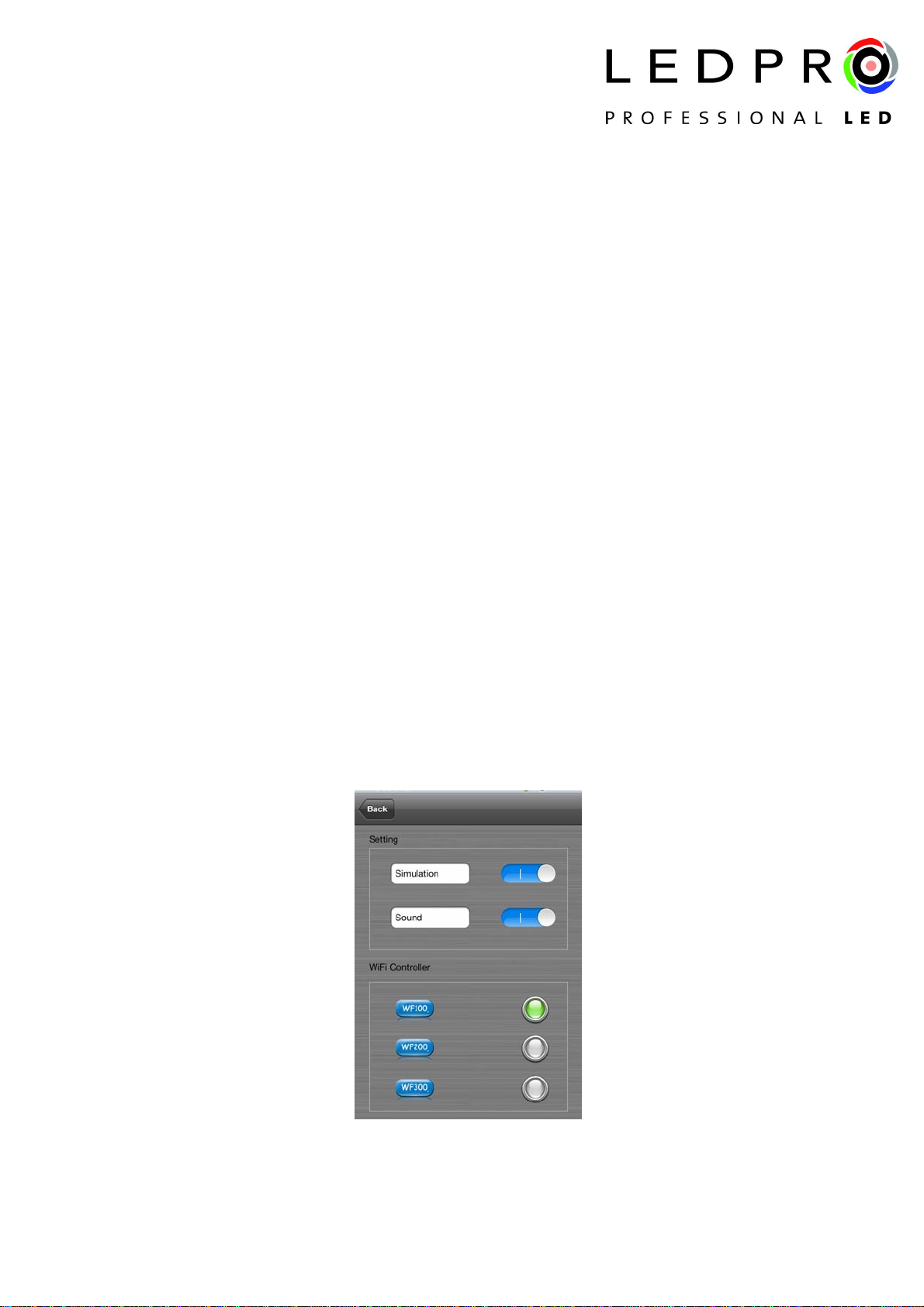
A.The simulation switch
Open software into the simulation interface, there is no need to connect controller, convenient software
demo.Closing into online control state.
B. Voice switch
Open the close touch prompt.
C. Radio button
Choose current need to control equipment.
D. Set parameter
Click into WF200,the slave controller setting page:
RunMode:
Choose current run mode.when slave controller connect RGB strip is choose “CD Mode”,color
temperature strip is choose “CT Mode”,single color strip is choose “DIM Mode” .
Slave Controller:
Slave Controller address and position parameter setting, Maximum support 16 points address.

4.Software operating
3.3.1
3.3.2
A. Site number
ALL: All sites synchronous control.
0-F: Slave controller site number,for the selected site control alone, other sites without control.
B. Site position
The current control sites' position (in the setup set site position).
C. ON/OFF key
ON/OFF, before control LED, open on/off key. After click OFF then close LED equipment
D. Color disk
Color dish function completely different in three modes: under CD mode is adjust color,under CT mode is
adjust color temperature, under DIM mode is adjust brightness .
E. Mode key
Controller built-in mode switch.
F. Speed/brightness
Static mode adjust brightness, dynamic mode adjust the speed.
G. Color dish color value
Show the current color value.
IV. LED-WiFi Controller Function Instruction
1. Working state instruction
Indicator light Function table
Power Power indicator light, long-time bright shows power supply
normally
Wifi Free time long-time bright, have wifi data enter flicker,
configuration wifi Ssid off
Link Receive the date, become flicker
Signal Flashing When a master and slave communication
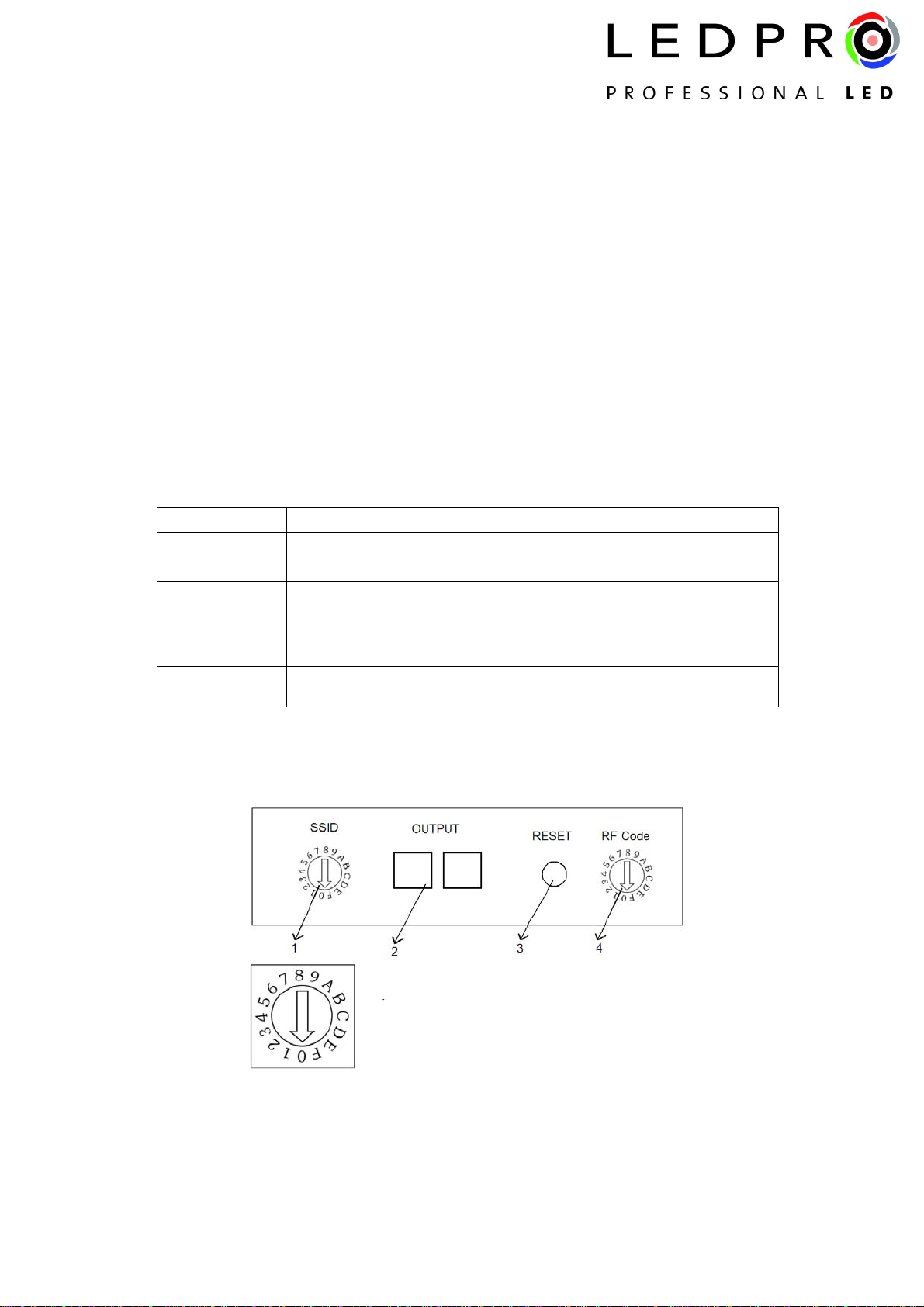
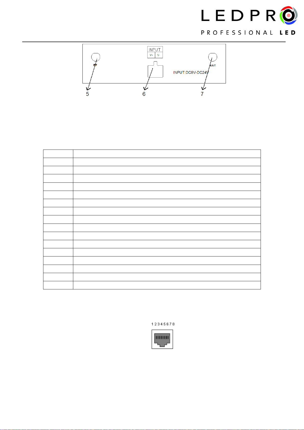
2. Connector instruction
1. Master controller SSID setting
Through dial code(SSID)to set LED-WiFi controller SSID number,corresponding table as above. Form 0
to 15, have 16 code in total, the corresponding SSID are below.That means use our product in same small area
can set 16 mutual isolation LAN, once the dial code changed after switch was dialed, Ssid number immediately
be modified, so you need to note that it need to search and connect again.
2. Master signal output end
Master controller signal output. If user don't use wireless control or distance is farther, the interface is
synchronizing signal output.
code SSID
0 LN001
1 LN002
2 LN003
3 LN004
4 LN005
5 LN006
6 LN007
7 LN008
8 LN009
9 LN010
A LN011
B LN012
C LN013
D LN014
E LN015
F LN016

Definition: Number Function
1 A(Data+)
2 B(Data-)
3 -
4 -
5 -
6 -
7 GND
8 GND
3. Master controller reset key
Recovery factory set. Restore the factory set password when press this button more than 10 seconds.
4. Setting master controller transt frequency
Through the Code switch (RF Code) to set LED-WiFi controller wireless transmitting frequency. When the
near distance exists within several master controller, in order to make each subsystem not mutual interference,
can fine-tune master transmite frequency, realize the subsystem isolation. The same system transmite
frequency and receive frequency must be equal also is to dial the code of the same position, otherwise can't
achieve synchronous control.
5.RF transmit antenna(433M).
6. Power input
Controller voltage range is DC5-24 V, more than working voltage may burn out controller.
7. ANT, WIFI signal reception.
V. Built-in mode form of controller
1.The mode form of RGB Control:
Mode number function remark
1 Static red
2 Static green
3 Static blue
4 Static yellow
5 Static purple
6 Static cyan
7 Static white
Brightness is
adjustable,Speed is
unadjustable

8 Three-color jumpy changing Speed and brightness are
adjustable
9 Seven-color jumpy changing Speed and brightness are
adjustable
10 Three-color gradual changing Speed and brightness are
adjustable
11 Seven-color gradual changing Speed and brightness are
adjustable
2. The mode form of color temperature control:
Mode number function remark
1 CW
2 80%CW
3 60%CW
4 40%CW
5 20%CW
6 PW(pure white)
7 20%WW
8 40%WW
9 60%WW
10 80%WW
11 WW
Brightness adjustable

3. The mode form of dimming Control:
VI. Explain installed hardware
1. Install ANT
ANT's installation drawing:
clockwise install WIFI antenna and anticlockwise take down the antenna.
Mode number function remark
1 1%
2 10%
3 20%
4 30%
5 40%
6 50%
7 60%
8 70%
9 80%
10 90%
11 100%
Brightness proportion

2. Install power supply
Controller adopt a wide voltage input DC5-24 V, easy to use.
VII System application figure
Notice: when use the wireless control, in order to achieve the best effect, the master should be placed in each
slave control center position.
Table of contents
Popular Lighting Equipment manuals by other brands


ADJ
ADJ ULTRA GO PAR7X User instructions

Daintree
Daintree GE current Tetra PowerStrip Snap DS installation guide

S.R.Smith
S.R.Smith rogue2 owner's manual

Chauvet
Chauvet Intimidator COLOR LED Quick reference guide

PARMIDA
PARMIDA PLED-CSTR27K-24V-20FT installation guide

Hay
Hay FIFTY-FIFTY WALL instruction manual


