SilverStar BACKPACKER MV User manual

SilverStar
BACKPACKER MV
www.silverstarmobility.com www.pridemobility.com
™

The symbols below are used throughout this owner's manual and on the product to identify warnings and important
information. It is very important for you to read them and understand them completely.
WARNING! Indicates a potentially hazardous condition/situation. Failure to follow
designated procedures can cause either personal injury, component damage, or
malfunction. On the product, this icon is represented as a black symbol on a yellow triangle
with a black border.
MANDATORY! These actions should be performed as specified. Failure to perform
mandatory actions can cause personal injury and/or equipment damage. On the product,
this icon is represented as a white symbol on a blue dot with a white border.
PROHIBITED! These actions are prohibited. These actions should not be performed at any
time or in any circumstances. Performing a prohibited action can cause personal injury
and/or equipment damage. On the product, this icon is represented as a black symbol with
a red circle and red slash.
SAFETY GUIDELINES
Copyright © 2008
Pride Mobility Products Corp.
INFMANU3698/Rev B/June 2008
Pride Provider:___________________________________________________________________
Address:________________________________________________________________________
Phone Number: ___________________
Purchase Date:____________________ Serial Number:______________________________
NOTE: This owner’s manual is compiled from the latest specifications and product information avail-
able at the time of publication. We reserve the right to make changes as they become necessary. Any
changes to our products may cause slight variations between the illustrations and explanations in this
manual and the product you have purchased. The latest/current version of this manual is available on
our website.
WARNING! An authorized Pride Provider or qualified technician must perform the initial
setup of this lift and must perform all of the instructions in this manual.
Please fill out the following information for quick reference:
088 609 661

Backpacker MV www.silverstarmobility.com 3
CONTENTS
I. INTRODUCTION ......................................................................................................................... 4
II. SAFETY ......................................................................................................................................... 5
III. INSTALLATION .......................................................................................................................... 8
IV. OPERATION ............................................................................................................................... 13
V. CARE AND MAINTENANCE ................................................................................................ 17
VI. TROUBLESHOOTING ............................................................................................................ 18
VII. WARRANTY................................................................................................................................19
APPENDIX I - SPECIFICATIONS ............................................................................................... 20

4 www.silverstarmobility.com Backpacker MV
Welcome to Pride Mobility Products Corporation (Pride). Congratulations on the purchase of your new
Backpacker MV Lift System. The Backpacker MV Lift System design combines the most advanced state-
of-the-art components with modern, attractive styling. We are certain that the design features and trouble-free
operation will add convenience to your daily living and ensure complete satisfaction.
At Pride, your safety is important to us. Please read and follow all instructions in this manual before
operating your lift system for the first time. These instructions were produced for your benefit. Your
understanding of these instructions is essential for the safe operation of your new lift system.
Pride is not liable for damage to property or personal injury arising out of the unsafe use of a Backpacker MV Lift
System. Pride is also not liable for any property damage or personal injury arising out of the failure of any person
and/or user to follow the instructions and recommendations set forth in this manual or any other instructions or
recommendations contained in other Backpacker MV Lift System related literature issued by Pride or contained
on the Backpacker MV Lift System itself.
INTERNET AND PRIVATE PURCHASES
If you purchased your product over the Internet or from a previous owner and you have any questions about the
safe use and/or maintenance of the product, please visit Silver Star’s web site www.silverstarmobility.com or
contact your authorized Pride Provider.
PURCHASER’S AGREEMENT
By accepting delivery of this product, you promise that you will not change, alter, or modify this product or
remove or render inoperable or unsafe any guards, shields, or other safety features of this product; fail,
refuse, or neglect to install any retrofit kits from time to time provided by Pride to enhance or preserve the safe use
of this product.
SHIPPING AND DELIVERY INFORMATION EXCHANGE
We want to hear your questions, comments, and suggestions about this manual. We would also like to hear about
the safety and reliability of your new lift system, and about the service you received from your authorized Pride
Provider.
Please notify us of any change of address, so we can keep you apprised of important information about
safety, new products, and new options that can increase your ability to use and enjoy your new lift system.
Please feel free to contact us at the address below:
Pride Mobility Products Corporation
Attn.: Customer Care Department
182 Susquehanna Ave.
Exeter, PA 18643-2694
customercare@pridemobility.com
1.800.424.8205
NOTE: If you ever lose or misplace your product registration card or your copy of this manual, contact
us and we will be glad to send you a new one immediately.
I. INTRODUCTION

Backpacker MV www.silverstarmobility.com 5
II. SAFETY
PRODUCT SAFETY SYMBOLS
The symbols below are used on the lift system to identify warnings, mandatory actions, and prohibited
actions. It is very important for you to read and understand them completely.
Crush Hazard—Moving parts can crush and cut. Keep hands clear.
Read and follow the information in the owner’s manual.
Maximum lifting capacity.
Do not use as a step.
Do not sit on mobility device while activating lift or during transport.
Do not sit on Power Chair or
Scooter while activating lift
or during transport.
Crush Hazard—Moving lift can crush. Keep feet clear during operation.
Avoid exposure to rain, snow, ice, salt, or standing water whenever possible.
Maintain and store in a clean and dry condition.
Do not remove cover! Only authorized personnel may service this equipment.
Refer to manual for important safety information.
Keep area clean and dry and free of obstructions.

6 www.silverstarmobility.com Backpacker MV
II. SAFETY
Explosive conditions exist!
Corrosive chemicals contained in battery.
Wear safety goggles.
Contains Lead.
Use only AGM or Gel-Cell batteries to reduce the risk of leakage or explosive
conditions.
Disposal and recycling-Contact your authorized Pride Provider for information on
proper disposal of your Pride product and its packaging.
Do not allow unsupervised children to play near the lift while the batteries are
charging.
Keep tools and other metal objects away from battery terminals. Contact with
tools can cause electrical shock.
Pinch/Crush points created during assembly.

Backpacker MV www.silverstarmobility.com 7
LIFTING CAPABILITIES
The Backpacker MV Lift System is designed for a maximum lifting capacity of 350 lbs. (158 kg). Under no
circumstances should the Backpacker MV Lift System be made to exceed this weight limit. Subjecting the lift
system to the strain of lifting more than it is designed to may cause it to fail, resulting in damage to the mobility
device and/or the lift operator. Refer to the mobility device owner’s manual for information on the overall weight of
the mobility device before lifting.
MANDATORY! Adding accessories, oversize batteries, or a different seat will increase the
weight of your mobility device. Verify with your authorized Pride Provider that the total
weight of your mobility device, including additions, DOES NOT exceed 350 lbs. (158 kg).
INSTALLATION
Your Backpacker MV Lift System is an inside SUV lift designed for installation into various brands of SUVs, full-
sized and mini vans. Read and fully understand the installation instructions provided in this manual and related
literature for your brand of vehicle before installing the lift system.
LIFTING NON-PRIDE PRODUCTS
The Backpacker MV Lift System is an extremely versatile device which users may employ to lift items other than
Pride products. Pride has no control over such use, nor can Pride anticipate every possible use to which a Back-
packer MV Lift System may be put. Lifting non-Pride products with the Backpacker MV Lift System is done at
the operator’s own risk, and Pride accepts no liability for damage or injury resulting from such use.
PRELIFT INSPECTION
Before operating the Backpacker MV Lift System, conduct a careful survey of your surroundings to ensure that
the lift system has a clear path of operation. Remove any possible obstructions before operating the lift and do not
allow children to operate or play near the lift. Ensure that all parts of the lift system are completely fastened before
loading the mobility device onto the lift platform, and make sure the mobility device is properly secured before
operating the lift system.
OPERATOR POSITIONING
The operator of the lift should stand a safe distance from the unit being lifted/lowered to ensure that his/her
feet are never positioned under the raised lift platform. The operator should also keep his/her hands clear of the lift
system during operation.
TRANSPORT VEHICLE POSITIONING
Be sure your vehicle is parked on flat, level ground before attempting to load, lift, or remove a mobility
device with the Backpacker MV Lift System. Make sure the vehicle emergency park brake is engaged before
loading or unloading a mobility device.
II. SAFETY

8 www.silverstarmobility.com Backpacker MV
III. INSTALLATION
BACKPACKER MV LIFT SYSTEM INSTALLATION
WARNING! The Backpacker MV Lift should be installed by an authorized service
technician only.
WARNING! At least two people should lift the Backpacker MV into the rear of the vehicle.
Use proper lifting techniques and avoid lifting beyond your physical capability.
WARNING! Avoid pinch points! Do not hold the lift frame by the pivot points when installing
the Backpacker MV.
NOTE: Use only the supplied hardware to install the Backpacker MV Lift System.
Follow these steps to install the Backpacker MV:
1. Install the Backpacker MV securement kit to the vehicle. Refer to the installation instructions supplied with the
securement system.
NOTE: Securement systems vary depending on vehicle manufacturer. Refer to the installation
instructions supplied with your securement system or contact your authorized Pride Provider for
more information.
2. Connect the Backpacker MV to a power source. See “Wiring Harness Installation.”
NOTE: If your lift is equipped with an optional onboard battery, refer to “Onboard Battery Installation.”
3. Ensure that all mounting hardware is fully tightened once the lift has been centered and all required clearances
have been achieved.
NOTE: If there is not adequate clearance between the bumper and the platform frame, you may need to
install an end support bracket. Remove the Backpacker MV from the van and install the end support
bracket close to the rear door opening. Reinstall the lift into the van, making sure that the bolts pro-
truding from the bottom plate of the Backpacker MV closest to the vehicle door snap into the tapped
holes on the top of the end support bracket.
NOTE: It may be required to trim the rear inside sill to achieve the adequate platform clearance with
the platform under load.
4. Run the Backpacker MV through an entire lift cycle. Lower the platform to the ground and then raise the
platform to the fully stowed position in the van. See IV. “Operation.”
NOTE: Ensure the transit screw and washer have been removed from the front of the lift and the rubber
bushing has been installed before operation. See figures 1 and 2.
NOTE: Pay attention to the path of the lift platform during operation. Make sure the lift does not rub
against or interfere with the vehicle in any way. If you notice any contact between the lift platform and
the vehicle, stop lift operation immediately and contact your authorized Pride Provider for assistance.

Backpacker MV www.silverstarmobility.com 9
III. INSTALLATION
Figure 1. Transit Screw Removal
WARNING! Release the “DOWN”
button when the lift platform
touches the ground. Do not allow
the motor to run after the lift
platform has touched the ground.
Allowing the motor to run will
increase the pressure on the lift
platform and may result in product
or vehicle damage.
Wiring Harness Installation
The wiring harness is approximately 25 ft. (7.62
meters) long and will accommodate most vehicles.
NOTE: You may wish to perform a practice run
before installing the wiring harness. Route a
piece of light rope (equivalent to the gage of the
wiring harness) along the anticipated path ob-
serving contact points, potential rubbing/chaf-
ing points, and any sharp edges. Remove sharp
edges with a fine grade file, then treat the steel
with a rust inhibitor or metal sealant.
WARNING! Route the wiring
harness through the vehicle rather
than under the vehicle to avoid
coming in contact with sharp
edges, extreme temperatures,
moving parts, and roadway debris.
Power shorts may occur if wires
come in contact with hot exhaust
parts or sharp edges.
WARNING! Never attach the wiring
harness to a secondary power
source. Do not attempt to use
trailer wiring to power the lift
system. The wiring harness must
be connected directly to the
vehicle battery.
RUBBER BUSHING
RUBBER BUSHING
TRANSIT SCREW
WASHER
Figure 2. Rubber Bushing Location/Installation
10 www.silverstarmobility.com Backpacker MV
III. INSTALLATION
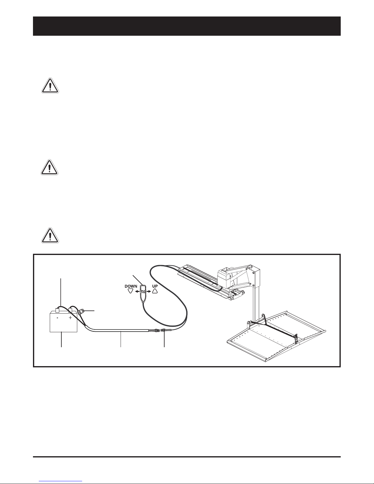
Figure 3.Wiring Harness Installation
GROUNDINGWIRE HAND CONTROL
FUSE
VEHICLE BATTERY WIRINGHARNESS LIFT WIRING CONNECTION
Follow these steps to route the Backpacker MV wiring harness:
1. Route the lift system wiring harness (starting at the lift) through the interior of the vehicle until you reach the
vehicle battery. See figure 3.
WARNING! Avoid routing the wire harness where it will interfere with or become pinched
by the securement system.
2. Conceal the harness behind or under the interior panels (there should be existing holes). Be certain that the
harness is protected with a rubber grommet when passing it through the metal panels and into the engine
compartment.
3. Inside the engine compartment, secure the harness to the firewall and the inner fender with plastic wire ties. Use
care not to cause abrasions to the wiring harness. It is important to secure the wiring harness at various points
along its run of the vehicle.
WARNING! Do not cut or shorten the wiring harness. If the harness is too long, coil the
excess wire and secure it with plastic wire ties.
4. Remove the 15-amp fuse from the wiring harness. See figure 3.
5. Connect the red wire to the positive (+) terminal and the black (grounding) wire to the negative (-) terminal
of the vehicle battery.
6. Reinstall the 15-amp fuse to the wiring harness.
WARNING! Before operating the lift, inspect the wiring harness for proper routing and grounding.
Improper routing can cause damage to the harness, and improper grounding can cause damage
to the electrical system.

Backpacker MV www.silverstarmobility.com 11
III. INSTALLATION
Optional Onboard Battery Pack Installation
The optional onboard battery is designed for easy in-
stallation as it does not require wires to be routed
through or under the vehicle. If using the optional Type
II onboard battery pack, please refer to the manual
supplied with the pack for proper operating instruc-
tions and harness connections.
Follow these steps to install the onboard battery
(Type I):
1. Remove the rubber caps and nuts from the protrud-
ing bolts on the side of the lift motor housing. See
figure 4.
2. Slide the spacer bar onto the protruding bolts, if not
already installed.
3. Mount the battery case onto the protruding bolts and
secure into position with the nuts and rubber caps
removed earlier. See figure 4.
4. Insert the onboard battery into the battery case, making
sure that the connector on the bottom of the battery
aligns and fully connects with the mating connector
inside the battery case.
5. Connect the male connector on the battery cable
to the female connector at the base of the Back-
packer MV.
6. Secure the battery cable to the other cables with
wire ties.
Follow these steps to install the onboard battery
(Type II):
1. Remove the rubber caps, nuts, and spacer bar from
the protruding bolts on the side of the lift motor hous-
ing. See figure 5.
2. Mount the battery pack base onto the protruding bolts
and secure into position with the nuts removed ear-
lier. See figure 5.
3. Insert the onboard battery into the battery pack base,
making sure that the connector on the bottom of the
battery aligns and fully connects with the mating con-
nector inside the battery pack base.
4. Connect the male connector on the battery cable to the
female connector at the base of the Backpacker MV.
5. Secure the battery cable to the other cables with
wire ties.
Figure 5. Onboard Battery Installation (Type II)
BATTERY
PACK
BATTERY
PACKBASE
LIFT MOTOR
HOUSING
Figure 4. Onboard Battery Installation (Type I)
SPACERBAR
NUTS
12 www.silverstarmobility.com Backpacker MV
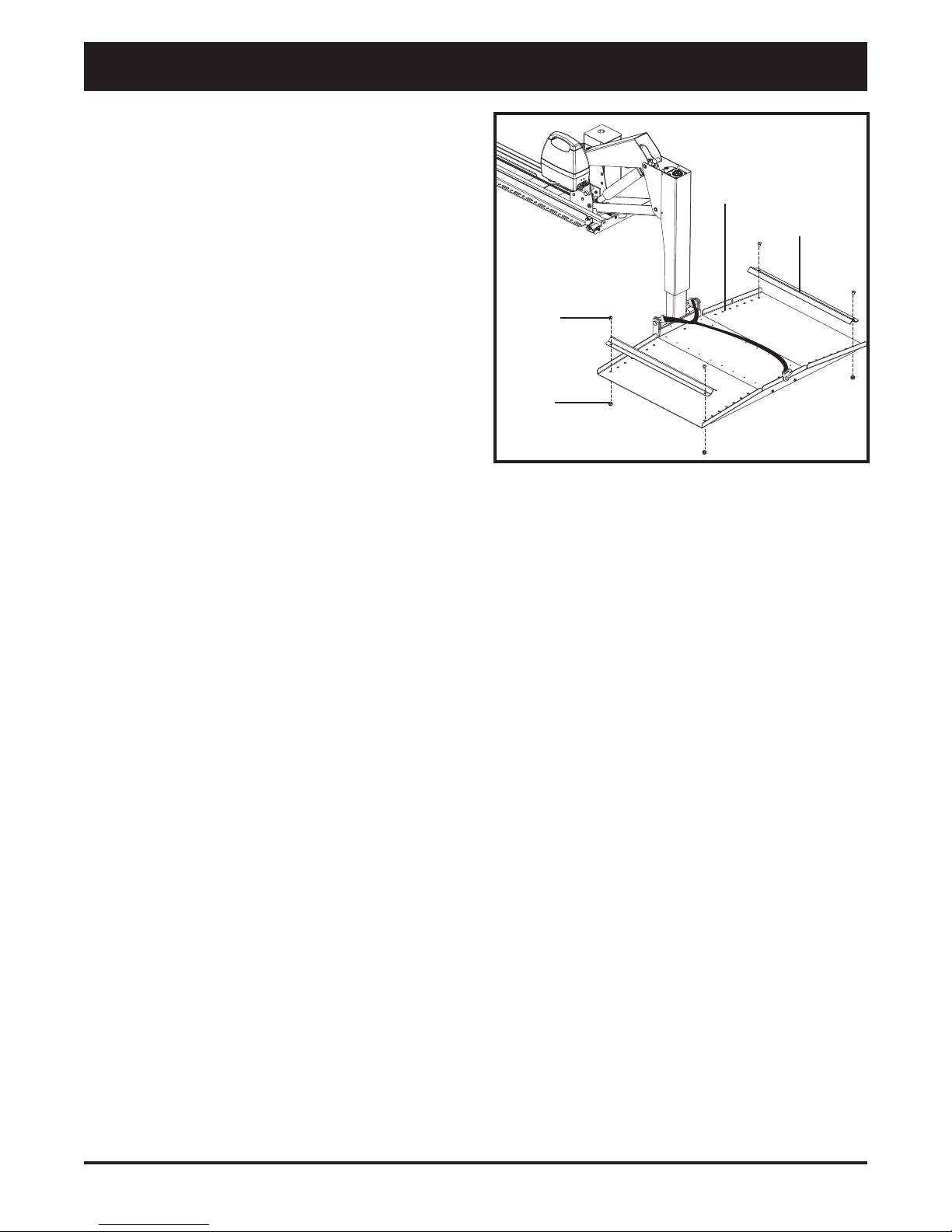
NUT
BOLT
Figure 6.Wheel Chock Installation
WHEELCHOCK
ADJUSTMENT HOLES
Wheel Chock Installation
Your lift is supplied with two adjustable wheel chocks that
aid in centering your mobility device during loading. See
figure 6.
Follow these steps to install the wheel chocks:
1. Drive your mobility device onto the lift platform,
positioning it as near to the center as possible.
2. Position the wheel chocks on the platform.
Scooters: Place a wheel chock in front of the front
wheel(s) and behind the rear wheels.
Power chairs: Place a wheel chock in front of the
drive wheels and behind the rear casters.
3. Take note of the adjustment holes the wheel chocks
align with on the platform and remove the chocks.
NOTE: For larger scooters, the wheel chocks may
be positioned to the inside of each wheel.
4. Remove the mobility device from the lift platform.
5. Raise the platform high enough to be able to install
hardware from beneath it.
6. Place the wheel chocks onto the lift platform and
secure them with the supplied bolts and nuts.
NOTE: Make sure the mobility device is properly
secured with the Y-strap before operating the lift or
transporting the mobility device.
III. INSTALLATION
Backpacker MV www.silverstarmobility.com 13
IV. OPERATION
BACKPACKER MV LIFT SYSTEM OPERATION
The Backpacker MV Lift System is designed to lift an unoccupied mobility device from the ground and into the
cargo area of an SUV, full-sized or mini van for the purpose of easy transport.
WARNING! The Backpacker MV Lift System is intended for the transport of unoccupied
mobility devices only. Do not sit on mobility device while activating lift or during transport.
WARNING! Make sure the lift system
is clean, dry, and free of obstructions
before operating.
Follow these steps to load a mobility device with the
Backpacker MV Lift System:
1. Press and hold the “DOWN” button. See figure
7. The lift will move out of the van to its farthest
forward stop, then lower to the ground. Once the
platform has reached the ground, release the
“DOWN” button.
WARNING! Release the “DOWN”
button when the lift platform touches
the ground. Do not allow the motor to
run after the lift platform has touched
the ground. Allowing the motor to run
will increase the pressure on the lift
platform and may result in product or
vehicle damage.
NOTE: The lift motor is equipped with a slip clutch,
which emits a ratcheting noise at the end of each
horizontal (in and out) movement. This sound is
normal and does not indicate a problem with your
lift system.
WARNING! Maintain a safe distance
from the lift platform. Ensure your feet
are not positioned under the lift
platform and keep your hands clear
of the lift system during operation.
2. Set the speed control to the slowest setting and care-
fully drive the mobility device onto the lift platform,
being sure to center the mobility device between the
previously installed wheel chocks.
NOTE: You may wish to load the mobility device
while standing next to it using the manual freewheel
feature. Refer to the mobility device owner’s manual
for more information on manual freewheel mode.
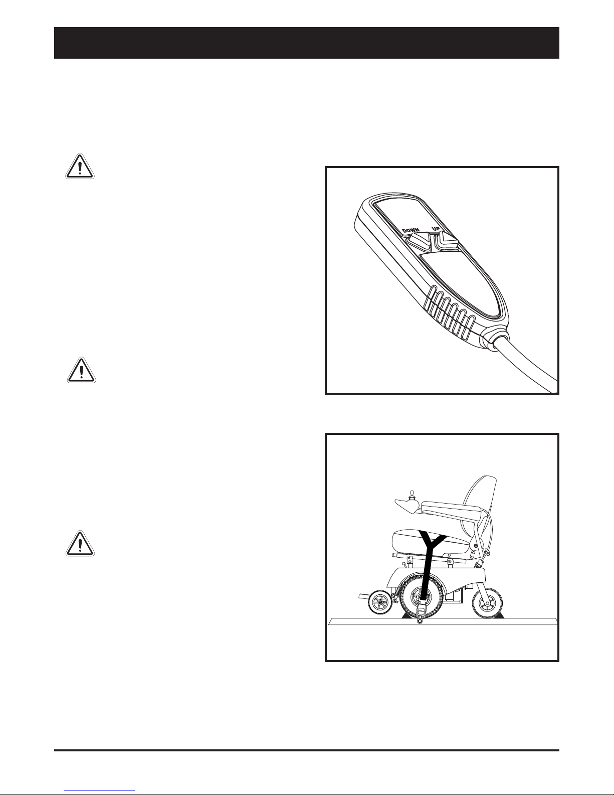
Figure 7. Hand Control
Figure 8.Y-Strap Positioning

14 www.silverstarmobility.com Backpacker MV
IV. OPERATION
3. Shut down the power to the mobility device, remove the key if applicable, and make sure the unit is in drive mode
(drive motors engaged). Refer to the mobility device owner’s manual for more information on drive mode.
WARNING! Never leave a mobility device in freewheel mode during lift system transport,
as the mobility device could roll or shift on its own.
4. Secure the mobility device to the platform by draping the Y-strap over the seat and buckling the strap se-
curely. See figure 8.
WARNING! Ensure the area behind the lift is clear of obstructions.
WARNING! Never attempt to secure the Y-strap over the seatback or armrests of
the mobility device.
MANDATORY! Always secure the mobility device to the lift with the Y-strap before
lift system operation or vehicle transport.
5. Pull the end of the strap tightly to remove any excess slack over the seat.
NOTE: Inspect the Y-strap before each use to ensure there are no signs of fraying or wear. Ensure that
the mobility device is secured properly before transport. Pride is not liable for damage or loss resulting
from improper securing of a mobility device.
6. Press and hold the “UP” button. See figure 7. The lift will move up to its highest lift point, then slide into the
SUV or van. Once the mobility device is stowed completely within the vehicle, release the button.
NOTE: Ensure that the SUV or van has enough headroom to accommodate the height of the mobility
device before loading it into the vehicle. Lower the tiller, adjust the seatback angle, or remove the seat if
necessary. Refer to the mobility device owner’s manual for more information on these adjustments.
WARNING! Do not exceed the load limits of your vehicle as specified by the vehicle
manufacturer.
WARNING! Do not sit on your mobility device while it is in a moving vehicle.
When you are ready to remove the mobility device from the vehicle, lower the platform to the ground, unfasten
the Y-strap, and drive the mobility device off of the platform. Once unloading is complete, return the lift platform
into the vehicle.

Backpacker MV www.silverstarmobility.com 15
The lift platform can be raised/lowered from two differ-
ent adjustment openings located at the top of the lift. The
larger (front) adjustment opening (see figure 9) requires
more energy but less revolutions to raise/lower the plat-
form, while the smaller (rear) adjustment opening (see
figure 9A) needs less energy but more revolutions.
PROHIBITED! DO NOT use the flex-
shaft when manually raising or
lowering the lift platform while using
the method illustrated in figure 9.
Attach the needed hardware directly
to the drill.
PROHIBITED! Never manually move
the lift backward with the lift
platform in the lowered position.
Ensure the lift platform is fully raised
and the tower arm is completely
retracted. See figure 11.
To operate the manual override:
1. Secure the appropriate end of the flex-shaft to a drill,
and depending on which part of the lift you want to
move, attach the appropriate hardware to the other
end of the flex-shaft. See figures 9A, 10, and 11.
2. Insert the flex-shaft into the appropriate adjustment
opening of the Backpacker MV.
3. Operate the drill to ensure the lift is moving in the
desired direction. Change the spin direction of the
drill if needed.
4. Operate the drill until the lift reaches the de-
sired position.
NOTE: When a power drill is not available, the
manual adjustment wrench can be used. See figure
11. Attach the smaller opening of the manual ad-
justment wrench to the flex-shaft or hex hardware
and rotate manually in the direction in which you
want the lift to move.
IV. OPERATION
MANUAL OVERRIDE OPERATION
The Backpacker MV is equipped with a manual override feature that, in the event of a power failure, allows the
lift to be manually positioned. Using the supplied tools, it is possible to elevate or lower the platform, raise or
lower the tower arm, and move the lift forward or backward.
NOTE: The hardware needed for manual operation is included with the Backpacker MV. (Drill
not included.)
Figure 9A. Raise Or Lower The Platform (Remove
Screw To Expose The Adjustment Opening)
Figure 9. Raise Or Lower The Platform
(DO NOT Use The Flex-Shaft For This Operation)
LIFT PLATFORM
HARDWARE
HARDWARE
FLEX-SHAFT

16 www.silverstarmobility.com Backpacker MV
IV. OPERATION
Figure 11. Front-To-Back Movement
HARDWARE
Figure 12. Manual Adjustment Wrench
Figure 10. Raise Or Lower The Tower Arm
TOWERARM
HARDWARE

Backpacker MV www.silverstarmobility.com 17
V. CARE AND MAINTENANCE
CARE AND MAINTENANCE
Your lift system requires a minimal amount of care and maintenance. If you do not feel confident in your ability to
perform the maintenance listed below, you may schedule inspection and maintenance at your authorized Pride
Provider. The following areas require periodic inspection and/or care and maintenance. Failure to perform the
required maintenance procedures at the required intervals may void your warranty.
Wiring Harness and Hand Control
The wiring harness should be checked periodically for corrosion and/or decay. Contact your authorized Pride
Provider if the wiring harness needs to be replaced.
Avoid leaving the hand control in areas where it will be exposed to inclement weather or temperature extremes.
Exposure to the elements may cause damage to the hand control.
WARNING! Avoid exposure to rain, snow, ice, salt, or standing water whenever possible.
Maintain and store in a clean and dry condition.
Lift Platform/Metal Components
Check the lift platform for wear or damage. Contact your authorized Pride Provider for repair or replacement.
The lift platform surface may become slippery if exposed to moisture (ice, snow, rain, mist/spray conditions,
etc.). Use caution when loading/unloading a mobility device in these conditions and wipe off any excess
moisture from the lift platform.
Regularly inspect the metal lift components for scratches. Treat any problem areas with a rust inhibitor or metal
sealant.
MAINTENANCE SCHEDULE:
Perform prior to daily use:
Inspect all external electrical connectors for damage and replace if necessary.
Check for damaged or loose hardware. Tighten or replace if necessary.
Perform every 6 months:
Inspect all mounting hardware for defects and a secure fit. Any loose hardware should be tightened or replaced if
necessary.
Perform every 6 – 12 months:
Lubricate chains with “general purpose petroleum-based grease.”
Lubricate the truck drive shaft with “petroleum-based anti-seize lubricant” only.
Inspect the base rollers and replace as necessary.
If base rollers were replaced, readjust the elevator bolt for proper alignment of parallel arms.
Inspect chain for proper tension and adjust as necessary.
NOTE: The chain should have 1 in. (2.5 cm) of deflection when the truck is fully extended contacting
the front microswitch.
Perform every 30 months:
Remove and inspect the pivot bolts on the parallel arms and lubricate or replace as necessary.
NOTE: Use only “petroleum-based anti-seize lubricant.”

18 www.silverstarmobility.com Backpacker MV
VI. TROUBLESHOOTING
TROUBLESHOOTING
Any electromechanical device occasionally requires some troubleshooting. However, most of the problems that
may arise can usually be solved with a bit of thought and common sense. Many of these problems occur because
the batteries are not fully charged or because the batteries are worn down and can no longer hold a charge.
What if the motor on my lift system will not operate?
Make sure the onboard battery or vehicle battery is fully charged.
Make sure all connections to the motor and battery are secure.
Check the wiring harness for signs of wear or decay. Replace the harness if necessary.
What if the lift system operates slowly up or down?
Make sure the onboard battery or vehicle battery is fully charged.
Make sure all connections to the motor and battery are secure.
Check the wiring harness for signs of wear or decay. Replace the harness if necessary.
What if the lift platform does not lower completely to the ground?
Check to make sure that the area under the lift platform is free from obstructions.

Backpacker MV www.silverstarmobility.com 19
VII. WARRANTY
THREE-YEAR TRANSFERABLE LIMITED WARRANTY
For three (3) years from the date of purchase, Pride Mobility Products will repair or replace at our option, free of
charge, any mechanical or electrical component found upon examination by an authorized representative of Pride
to be defective in material and/or workmanship.
This warranty does not extend to those items, which may require replacement due to normal wear and tear.
Labor, service calls, shipping, and other charges incurred for repair of the product, unless specifically autho-
rized by Pride Mobility Products Corporation INADVANCE, are excluded.
Exclusions also include components with damage caused by:
Contamination
Abuse, misuse, accident, or negligence
Battery fluid spillage or leakage
Commercial use, or use other than normal
Improper operation, maintenance, or storage
Repairs and/or modifications made to any part without specific consent from Pride Mobility Products Corpo-
ration.
Circumstances beyond the control of Pride
ONE-YEAR WARRANTY
The battery is covered by a separate one (1) year warranty provided by the battery manufacturer. The batteries are
not warranted by Pride Mobility Products Corporation.
SERVICE CHECKS AND WARRANTY SERVICE
An authorized Pride Mobility Products Provider must perform warranty service. Do not return faulty parts to Pride
Mobility Products without prior written authorization.All transportation costs and shipping damage incurred while
submitting parts for repair or replacement is the responsibility of the purchaser.
Failure to follow the instructions, warnings, and notes in the owner’s manual and those located on your Pride lift
product can result in personal injury or product damage and will void Pride’s product warranty.
There is no other express warranty.
IMPLIED WARRANTIES
Implied warranties, including those of merchantability and fitness for a particular purpose, are limited to one (1)
year from the date of purchase and to the extent permitted by law. Any and all implied warranties are excluded.
This is the exclusive remedy. Liabilities for consequential damages under any and all warranties are excluded.
Some states do not allow limitations on how long an implied warranty lasts or do not allow the exclusion of
limitation incidental or consequential damages. The above limitation or exclusion may not apply to you.
This warranty gives you specific rights, and you may also have other rights, which vary from state to state.
Please fill out and return the product registration card to Pride Mobility Products. This will aid Pride in providing
the best possible technical and customer service.

20 www.silverstarmobility.com Backpacker MV
SPECIFICATIONS
Lift System Dimensions Overall Base Rail Length: 43.5 in. (110.49 cm)
Overall Base Rail Width (excluding platform): 11.5 in. (29.21 cm)
Overall Height: 30.75 in. (78.10 cm)
Platform Width: 44 in. (111.76 cm)
41in. (104 cm) usable surface
Platform Depth: 28.25 in. (71.75 cm)
Total Lift System Weight 193 lbs. (87.54 kg) including standard platform
Maximum Lift Capacity 350 lbs. (158 kg)
Mobility Device Dimensions Length (from center of front wheel to center of rear wheel): 41 in. (104 cm)3
Height: 34 in. (86.36 cm)1
Width: 27 in. (68.58 cm)
Maximum Lift Travel Distance 37 in. (94 cm) vehicle floor to ground
Motor Fully sealed, 12-volt DC
Onboard Battery (Type I) Battery: 12-volt, 18Ah
Weight: 12 lbs. (5.44 kg)
Charger: 110-volt, off-board2
Onboard Battery (Type II) Battery: 12-volt, 8Ah
With Integrated Battery Charger Weight: 10.5 lbs. (4.8 kg)
1Depending on vehicle dimensions.
2Use the supplied charger only.
3 Overall length of your mobility device will vary. Verify that the unit’s wheelbase is equal to or less than 41 in.
(104 cm) prior to operation. In addition, verify that the overall length of your mobility device will fit into the rear
of your vehicle before stowing.
APPENDIX I - SPECIFICATIONS
BATASMB1030
BATASMB1049
SPECIFICATIONS
Table of contents
Other SilverStar Lifting System manuals

Popular Lifting System manuals by other brands


HAWEKA
HAWEKA AirgoLift operating instructions

BHM Medical
BHM Medical OXFORD VOYAGER PORTABLE user manual

Harrington
Harrington CX Series owner's manual

pewag
pewag levo hook LH5 Original operating manual

Genie
Genie GTH-4013 SX Service manual

John Bean
John Bean EELR537A Installation, operation & maintenance manual

Aquatec
Aquatec orca Operating instruction

morse
morse 515M-T-124 Operator's manual

Globaljig
Globaljig Super Rotax user manual

Weaver
Weaver W-1500 Installation & operation manual

Lift-Rite
Lift-Rite Altra Owner's Manual, Operating Instructions Manual, and Replacement Parts Manual

Zenit
Zenit blueBOX Use and maintenance instructions