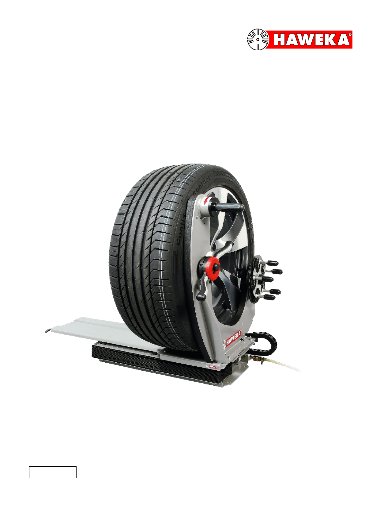
Wheel Lifting Device AirgoLift
HAWEKA - AirgoLift
Table of Contents
1. General Safety Instructions ..........................................................................................3
1.1 Explanation of symbols..............................................................................................3
2. Product Description ......................................................................................................4
2.1 Authorised intended use............................................................................................4
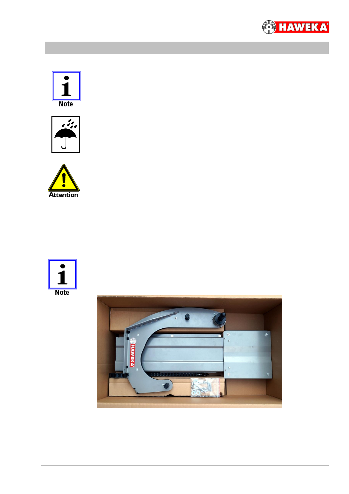
2.2 Transport weight and dimensions..............................................................................4
2.3 Technical Data...........................................................................................................5
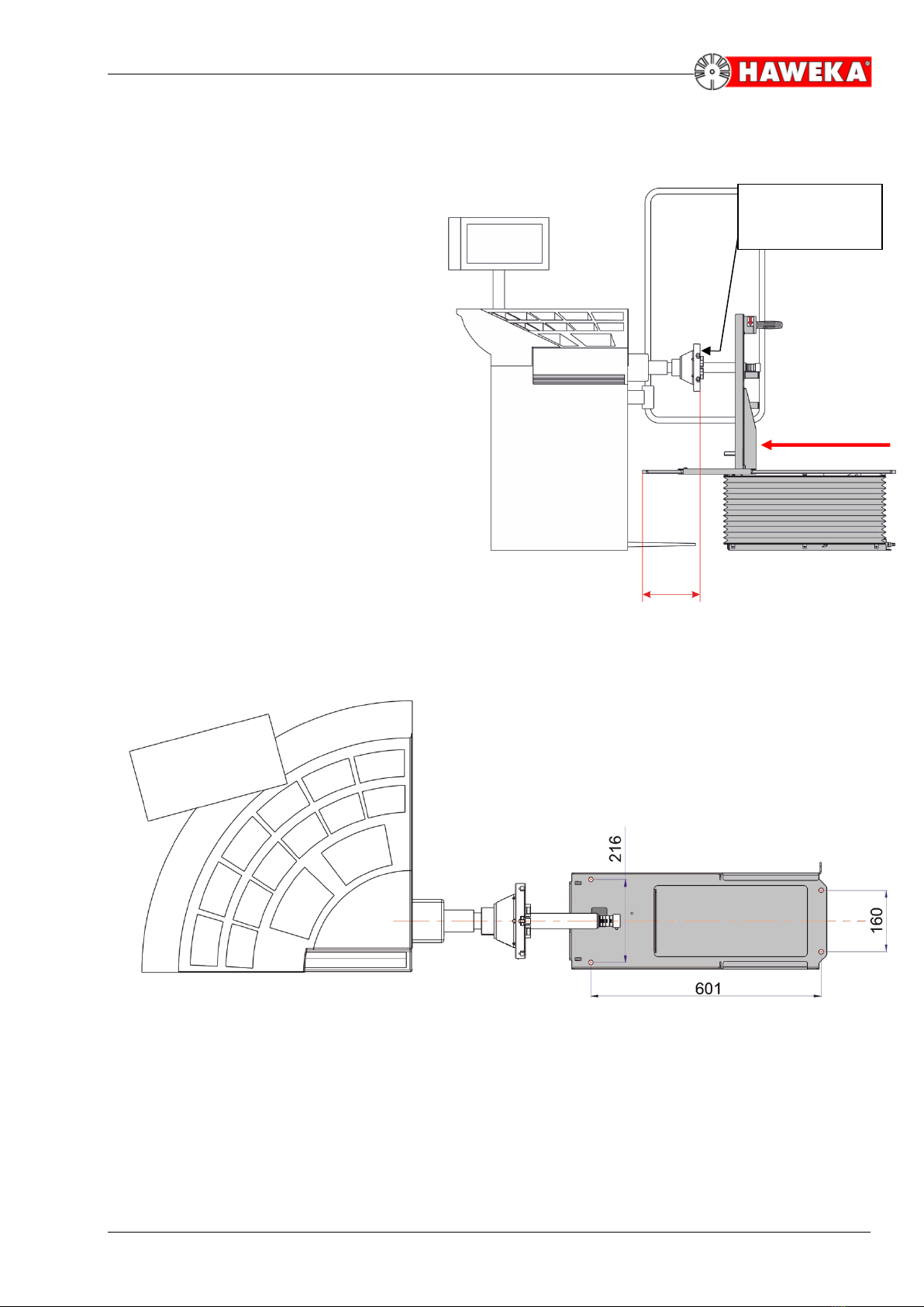
2.4 Dimensions................................................................................................................5
2.5 Description of device .................................................................................................6
3. Installation and Commissioning....................................................................................7
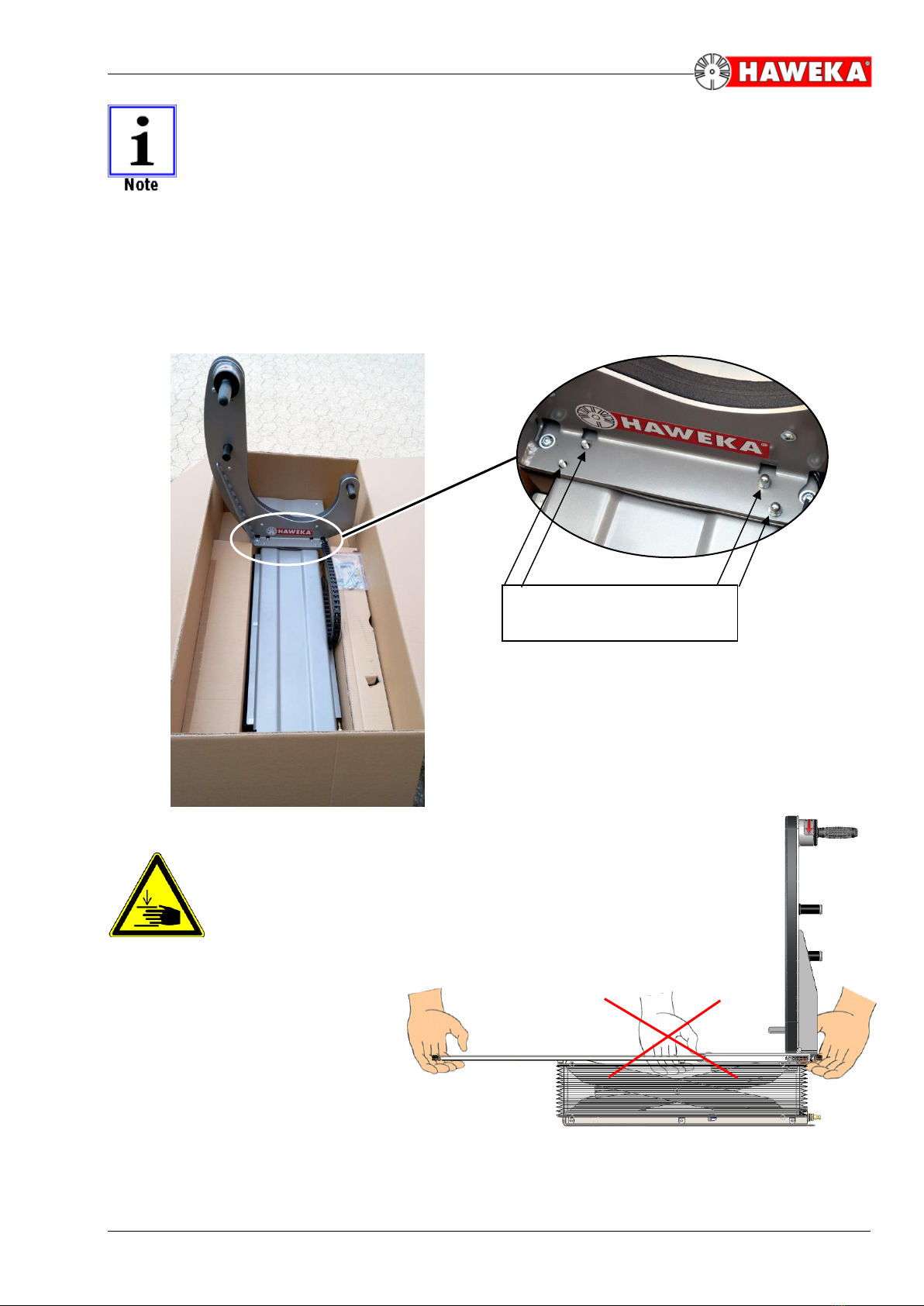
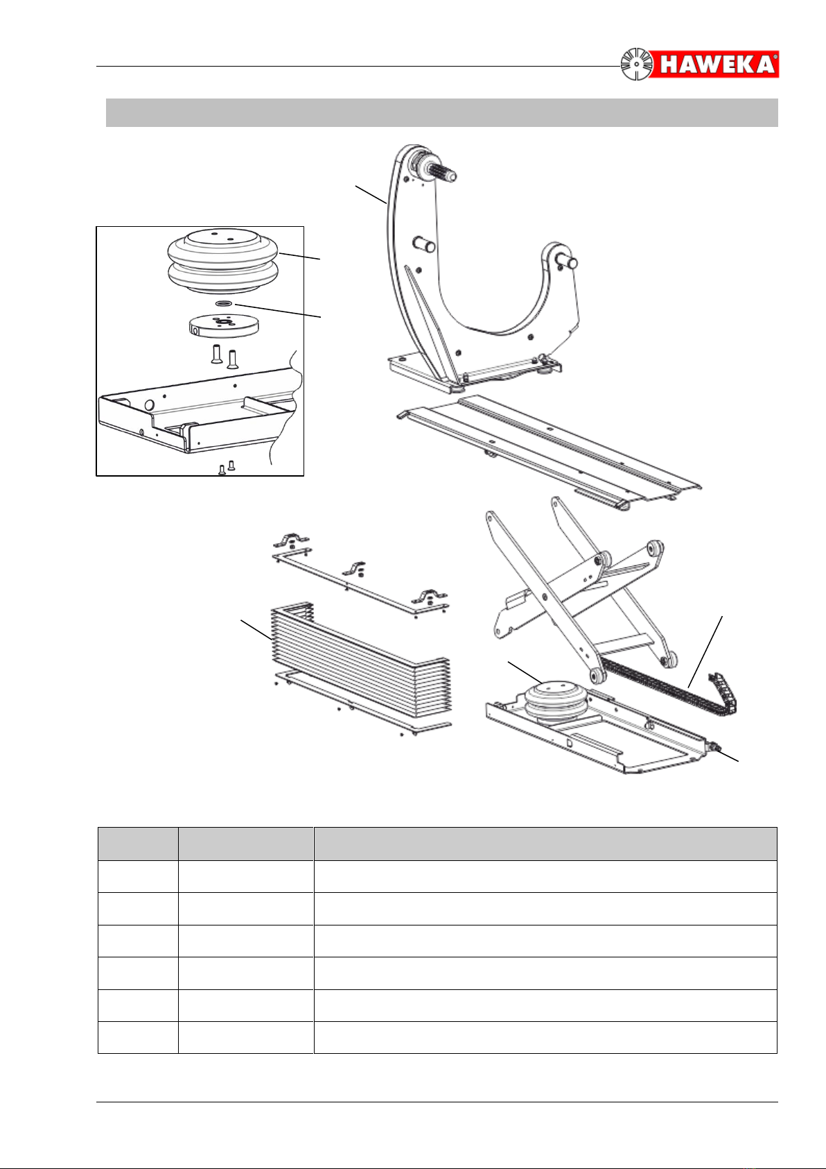
3.1 Assembly of the AirgoLifts.........................................................................................7
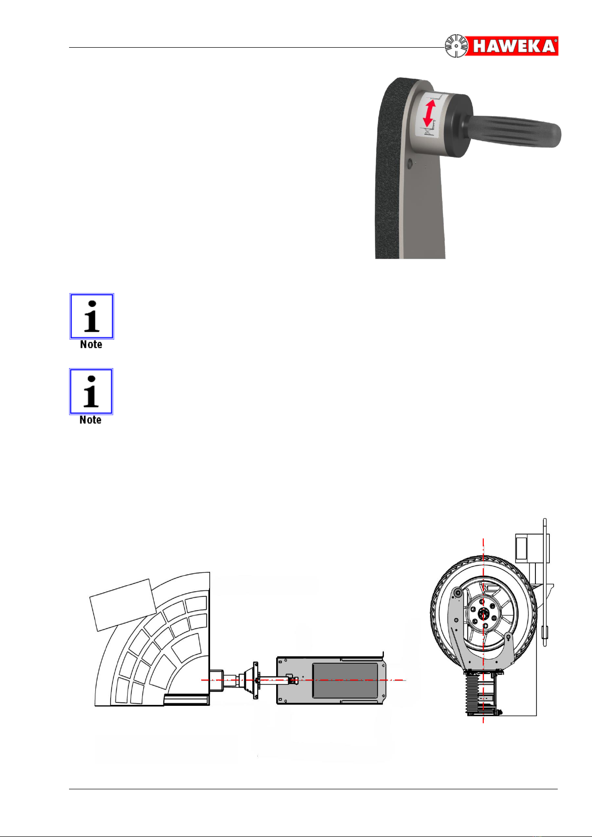
3.2 Function check...........................................................................................................9
3.3 Position in front of the wheel balancer.....................................................................10
4. Application and Operation ..........................................................................................12
5. Maintenance and Care ...............................................................................................13
5.1 General Care...........................................................................................................13
5.2 Setting the Lifting Speed..........................................................................................13
6. Troubleshooting and their Causes..............................................................................14
7. Spare Parts.................................................................................................................15
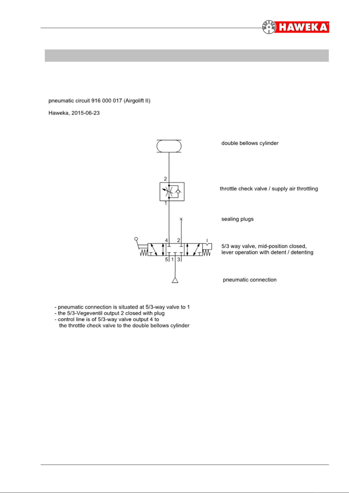
8. Pneumatic Diagram....................................................................................................17
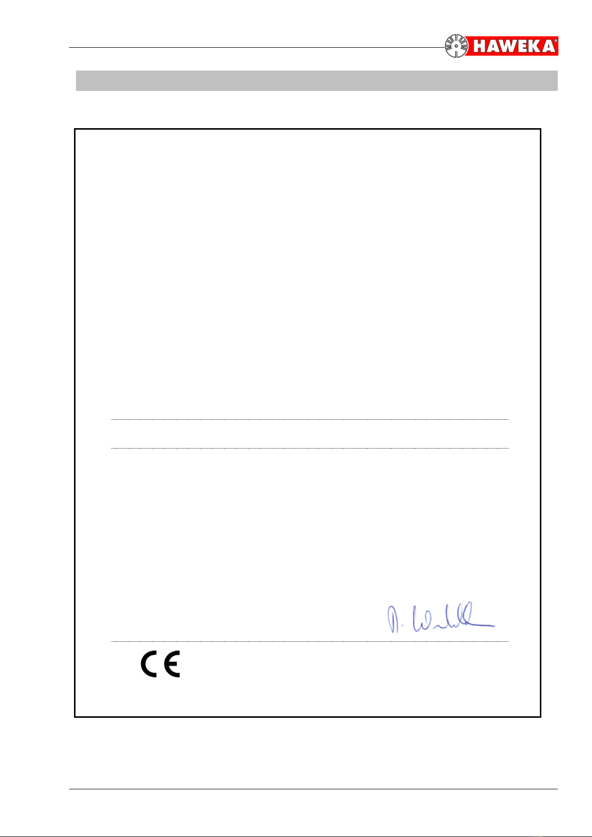
9. EC Declaration of Conformity.....................................................................................18
Last updated: November 2019
Subject to technical modifications.
Version 2.0
Figures: HAWEKA AG / D-30938 Burgwedel
Reproduction in any form is not permitted.