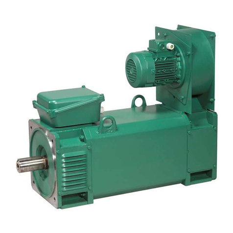
SilverWolf TEEKON AC-PM MOTOR 12HP Manual

Get the SilverWolf™ App at;
INSTALLATION
AND SERVICE
MANUAL
FITS:
Curtis Controller 1510/1515
ClubCar®Precedent® Onward®
2004 TO PRESENT
www.silverwolfmotors.com
PART # 05-000100 V2.0CC
© 2021 SilverWolf™Vehicles Inc. All rights reserved.
Part # PK-000012-CC
* Sold Separately
*2 Ga AC Power Cables – Required
for speeds greater than 19 MPH
*Smartphone
not included
AC GOLF CAR SPEED & RANGE
ENHANCEMENT KIT
™


2
INTRODUCTION ............................................................................................................................................................................. 3
Serial # Location & Recording ...............................................................................................................................................................................................................3
WARNINGS .................................................................................................................................................................................... 4
Safe Operating Warnings..........................................................................................................................................................................................................................4
PARTS LIST ...................................................................................................................................................................................5
INSTALLATION INSTRUCTIONS -CLUB CAR®PRECEDENT®-ONWARD®............................................................................................... 7
Installation & Servicing Warnings.......................................................................................................................................................................................................... 7
Controller & Module Overview................................................................................................................................................................................................................8
INSTALLATION INSTRUCTIONS- CLUB CAR®PRECEDENT®-ONWARD®48V ........................................................................................ 9
SILVERWOLF™APP SETUP & FEATURES........................................................................................................................................ 15
Features (Home Screen)..........................................................................................................................................................................................................................16
Vehicle Setup ..............................................................................................................................................................................................................................................17
Pre-Set Vehicle Modes..............................................................................................................................................................................................................................18
Advanced Settings.....................................................................................................................................................................................................................................18
Display Settings..........................................................................................................................................................................................................................................19
On-The-Fly Regen Braking......................................................................................................................................................................................................................20
TROUBLESHOOTING:.................................................................................................................................................................... 22
Diagnostics.................................................................................................................................................................................................................................................22
WARRANTY ................................................................................................................................................................................. 25
www.silverwolfmotors.comSilverWolf™Vehicles Inc.
TABLE OF CONTENTS
SILVERWOLF MOTORS INC.
PATENTS PENDING
AC-PM MOTOR
TECHNOLOGY BY
ACCELERATED SYSTEMS INC
PART #
10-000784
SERIAL #
SW12001
VOLTAGE
48-72V
HP
12
RATING
5500RPM
MADE IN CANADA
™

The owner, and all vehicle operators MUST Read and Understand All Warnings and Instructions in this manual and in the Vehicle Owner/
Operator’s Manual. The owner of this vehicle assumes all liability for accidents, injuries or damages if the warnings and instructions are
not followed.
SilverWolf™Vehicles Inc. assumes no responsibility for errors or omissions in this manual, in regards to liability or damages resulting from
the use of information contained in the manual. If it is lost or damaged please contact your local dealer or SilverWolf™Vehicles Inc..
SilverWolf™reserves the right to make changes to the controller, parts of the controller, accessories, labeling or instructions without
obligation to make these changes on units previously sold.
Product and specifications are subject to change without notice or obligation.
ATTENTION:
SILVERWOLF™AC-PM MOTOR & CONTROLLER KIT
SERIAL # LOCATION
Club Car®, Precedent®, and Onward® are registered trademarks of Ingersoll Rand, Inc., References to Club Car® on our web site or any
associated electronic or printed publication are solely for purposes of identifying golf carts.
3www.silverwolfmotors.comSilverWolf™Vehicles Inc.
PART MODEL SERIAL #
SILVERWOLF™AC MOTOR CONTROLLER BAC8000
SILVERWOLF™AC-PM MOTOR 12HP
SILVERWOLF™SMART MODULE By Model
12345
12345
12345
Motor
Controller
Module
Before installing this Kit, record or take a photo of the Serial # on all 3 of the Main Components.
INTRODUCTION
SILVERWOLF MOTORS INC.
PATENTS PENDING
AC-PM MOTOR
TECHNOLOGY BY
ACCELERATED SYSTEMS INC
PART #
10-000784
SERIAL #
SW12001
VOLTAGE
48-72V
HP
12
RATING
5500RPM
MADE IN CANADA
™

FAILURE TO FOLLOW THE
WARNINGS BELOW CAN DAMAGE
THE VEHICLE AND/OR CAUSE
SERIOUS INJURY OR DEATH!
WARNING!
DO NOT SWITCH THESE CABLES!
Cable is on the Positive Controller Post
Cable is on the Negative Controller Post
CHECK
Tighten the
5 Controller
Bolts with a
Torque Wrench to
53in-lbs/6 Nm
DO NOT
OVER TIGHTEN!
Wire Terminal
Must Always be
on the Bottom!
LOCK WASHER
1
2FLAT WASHER
CONTROLLER HARDWARE MUST BE INSTALLED IN THE ORDER SHOWN!
MAKE SURE TO READ and UNDERSTAND the OWNER’S INSTALLATION and SERVICE MANUAL and ALL WARNING LABELS with
this Motor & Controller Kit.
Installation must be done by a trained Golf Cart Technician.
• Any modifications or changes made to the Motor, Controller or Wiring Harness will void the manufacturers warranty. Contact your
dealer if the vehicle is not operating correctly.
• Always proceed with caution. Keep speed low and do not drive faster than conditions permit. The terrain, conditions and the operator’s
skill will determine a safe speed.
• Avoid sharp turns and do not accelerate quickly when turning; this can cause the vehicle to slide sideways or skid out of control.
Abrupt maneuvers or aggressive driving can cause a rollover even on flat open areas.
• This Motor & Controller will increase torque, but Does Not increase the GVWR (Gross Vehicle Weight Rating), Cargo capacity or Towing
capacity of the Vehicle. Always follow the Vehicle’s towing capacity rating as specified by the vehicle manufacturer.
• Do not leave children or pets unattended in or near the vehicle.
• Drive at a reduced speed and use extra caution when carrying passengers or cargo.
• Always look behind you before and while backing up.
• Reduce speed when towing and allow more room for stopping and turning.
• Drive with wheels straight when going up and down hills.
• Slow down and use brakes when going down hills.
• Never drive on hills with a slope greater than 15 degrees.
• Do not drive through fast flowing water or water above the floor of the vehicle.
• If you must cross shallow water, make sure to stop and inspect the area for sudden drop-offs, large rocks or slippery surfaces.
Always proceed with caution or choose a safer route.
• When towing this vehicle make sure the key is turned off, the Run/Tow switch is in Tow, and batteries main power is disconnected.
• Keep electrical components dry and DO NOT wash with direct stream or power washer.
• Keep the controller and the area around it clean and free of debris.
• Do Not submerge the Controller or it’s Parts.
• Vehicle and all parts must be serviced by qualified service personnel. For an authorized service location call 1-888-398-7078 or email
support@silverwolfmotors.com call
4www.silverwolfmotors.comSilverWolf™Vehicles Inc.
WARNING
SILVERWOLF MOTORS INC.
PATENTS PENDING
AC-PM MOTOR
TECHNOLOGY BY
ACCELERATED SYSTEMS INC
PART #
10-000784
SERIAL #
SW12001
VOLTAGE
48-72V
HP
12
RATING
5500RPM
MADE IN CANADA
™

PART DESCRIPTION PART # QTY
1 Model BAC8000 840A Motor Controller PC-000052-X 1
2 12 HP AC-PM Motor -10 Spline (Club Car®)PM-000002-CC 1
3SW Vehicle Smart Module w/BLE Connectivity
fits: Club Car®Precedent/Onward w/ Curtis®1510/1515 (16 Pin Connector) 10-000787 1
4 Controller Locking Plate 4” x 1” 20-001355 2
5 M6 x 12mm High-Strength Steel Flanged Hex Head Bolt (*Installed on Motor) 80-000585 3
6 M6 x 14mm Hex Head Bolt (*Installed on Controller) 80-000621 5
7 M6 Lock Washer (*Installed on Controller) 80-000622 5
8 M6 Flat Washer (*Installed on Controller) 80-000618 5
9 1/4” x 3/4” Hex Bolt 80-000586 4
10 1/4” Nylon Lock Nut 80-000588 4
11 11” Black Zip Ties 80-000590 8
Confirm that all parts listed below are with your kit before starting installation.
If you are missing parts please contact your local dealer or SilverWolf™Vehicles Inc.
5www.silverwolfmotors.comSilverWolf™Vehicles Inc.
2
13
8
Hardware
5
4
910
67
11
PARTS LIST - Club Car®Precedent
SILVERWOLF MOTORS INC.
PATENTS PENDING
AC-PM MOTOR
TECHNOLOGY BY
ACCELERATED SYSTEMS INC
PART #
10-000784
SERIAL #
SW12001
VOLTAGE
48-72V
HP
12
RATING
5500RPM
MADE IN CANADA
™

6www.silverwolfmotors.comSilverWolf™Vehicles Inc.
1
2
3456
HEAVY DUTY 2GA AC POWER CABLES
Part # PK-000012
(Sold Separately)
INCLUDED IN THE HEAVY DUTY 2GA POWER CABLE KIT
PART # PK-000012-CC
PART # QTY
12ga Motor Phase Cable for Club Car®Precedent -Yellow (36”) 40-000533-YL 1
2 2ga Motor Phase Cable for Club Car®Precedent -Blue (36”) 40-000533-BL 1
3 2ga Motor Phase Cable for Club Car®Precedent -Green (36”) 40-000533-GN 1
4 Main Positive Cable (from Battery + to Solenoid)- Red (30”) 40-000531 1
5 Main Negative Cable (from Battery - to Controller) - Black (24”) 40-000532 1
6 Positive Power Cable (from Solenoid to + on Controller)- Red (16”) 40-000534 1
RECOMMENDED PARTS
SILVERWOLF MOTORS INC.
PATENTS PENDING
AC-PM MOTOR
TECHNOLOGY BY
ACCELERATED SYSTEMS INC
PART #
10-000784
SERIAL #
SW12001
VOLTAGE
48-72V
HP
12
RATING
5500RPM
MADE IN CANADA
™

Tools Required
• Safety Glasses
• Gloves
• Standard Ratchet Set
• Standard Wrench Set
• 10mm Socket
• 10mm Wrench
• Torque Wrench
• Drill
• 1/4” Drill Bit
• 2 Automotive Jack Stands
• Lift Jack (2 ton or more)
• Wheel Chocks
7www.silverwolfmotors.comSilverWolf™Vehicles Inc.
Installation or Servicing of the SilverWolf
™
TEEKON Systems Must be done by a Trained Golf Car
Technician.
Before installing or servicing READ THE FOLLOWING:
• Make Sure that the Vehicle’s Electrical System is working properly and all components such as
the Run/Tow Switch, FWD/REV Switch, Brakes, Throttle and all Wiring are in good condition and
operating to Manufacturers Standards. If not they Must be repaired or replaced before installing
the SilverWolf
™
TEEKON Kit.
• The Vehicle Solenoid Must have a Pre-Charge Resistor on it.
• The Batteries Must be in Good Condition and each Battery Must hold a Full Charge!
• Make sure the Run/Tow Switch is in the Tow position
• The Key is turned OFF and removed from the Ignition
• The Parking Brake is Engaged
• Disconnect the Main (+) Positive and (-) Negative Cable on the Vehicle’s Battery System.
• Before testing the Vehicle make sure the Rear Wheels are off the ground and supported
with Automotive Jack Stands. The Front Wheels must be Chocked.
• The area around the vehicle must be clear. Keep all People, Children and Pets away from the
vehicle when installing, servicing or testing the vehicle.
• Read the
SilverWolf™TEEKON
Installation /Service Manual and All Warning Labels before servicing
or troubleshooting this Vehicle.
• The Motor, Controller and Module are sealed and can not be opened for service. To replace these
parts call your local dealer. Opening these parts will Void the Warranty.
• Wear Safety Glasses and Gloves when installing this Controller.
• Wear a Safety Shield when working in or near the Vehicle Battery Compartment.
• Use Insulated Tools to protect from electric shock.
• Never lay or drop tools on the Batteries or in the Vehicle Battery Compartment.
FAILURE TO FOLLOW THE
WARNINGS BELOW CAN DAMAGE
THE VEHICLE AND/OR CAUSE
SERIOUS INJURY OR DEATH!
WARNING!
DO NOT SWITCH THESE CABLES!
Cable is on the Positive Controller Post
Cable is on the Negative Controller Post
CHECK
Tighten the
5 Controller
Bolts with a
Torque Wrench to
53in-lbs/6 Nm
DO NOT
OVER TIGHTEN!
Wire Terminal
Must Always be
on the Bottom!
LOCK WASHER
1
2
FLAT WASHER
CONTROLLER HARDWARE MUST BE INSTALLED IN THE ORDER SHOWN!
FAILURE TO FOLLOW THE WARNINGS BELOW CAN DAMAGE
THE VEHICLE AND/OR CAUSE SERIOUS INJURY OR DEATH!
WARNING!
Golf Carts & Utility Vehicles must use a
Pre-charge Resistor on the Solenoid!
DO NOT SWITCH THESE CABLES!
Cable is on the
Positive Controller Post
Cable is on the
Negative Controller Post
CHECK
Tighten the 5 Controller Bolts
with a Torque Wrench to
70in-lbs/8 Nm
DO NOT OVER TIGHTEN!
Wire
Terminal
Must Always
be on the
Bottom!
LOCK
WASHER
FLAT
WASHER
1
2
CONTROLLER HARDWARE MUST BE INSTALLED IN THE ORDER SHOWN!
CLUB CAR®PRECEDENT®/ONWARD®
INSTALLATION INSTRUCTIONS
SILVERWOLF MOTORS INC.
PATENTS PENDING
AC-PM MOTOR
TECHNOLOGY BY
ACCELERATED SYSTEMS INC
PART #
10-000784
SERIAL #
SW12001
VOLTAGE
48-72V
HP
12
RATING
5500RPM
MADE IN CANADA
™

CONTROLLER & MODULE OVERVIEW
8www.silverwolfmotors.comSilverWolf™Vehicles Inc.
Vehicle Smart Module
1 Vehicle 16 Pin Vehicle Harness Connector
2-3 4WD 8 Pin SilverWolf™4WD System (optional)
Controller Wiring Locations
Connector Plug Location
To SilverWolf™
Controller
3
1
2
U+VW
-
STATUS
LIGHT
CLUB CAR®PRECEDENT®/ONWARD®
INSTALLATION INSTRUCTIONS
SILVERWOLF MOTORS INC.
PATENTS PENDING
AC-PM MOTOR
TECHNOLOGY BY
ACCELERATED SYSTEMS INC
PART #
10-000784
SERIAL #
SW12001
VOLTAGE
48-72V
HP
12
RATING
5500RPM
MADE IN CANADA
™

B
Before removing the original Controller & Cables take a photo or make a note of how the Cables run through the Controller Panel into
the Battery Compartment. Also note where the other smaller Cables on the Vehicle Harness and Controller connect ,they will need to be
connected to the New Harness and Controller in the same locations. Note: These connections will be shown in future steps in this manual.
1. Remove the 2 middle Batteries to allow access to the Controller Panel.
2. Remove the Torx Head Bolt on the Controller Panel and gently pull the Panel back in to the open area in Battery Compartment.
3. Remove the Cables going to the Controller, Motor and Solenoid, these will need to be replaced with the Heavy Duty 2ga Cable Kit
Part # PK000012-CC - Sold Separately
9www.silverwolfmotors.comSilverWolf™Vehicles Inc.
To complete the next steps see the photos on the next page.
1. Align the Controller into place as shown in the photo on the next page. Then mark the 4 holes on the Controller Locking Plates.
Remove the Controller and Plates and drill four 1/4” holes.
CAUTION: Be careful not to get to close to the RUN/TOW Switch.
Note: Some older model Club Car®Precedents may require the OBC to be move slightly to allow the controller to fit in place.
2. Loosely install one of the Controller Locking Plates with 2 of the 1/4” x 3/4” Hex Bolts and 1/4” Lock Nuts.
3. Insert the Controller as shown on the following page and loosely install the second Controller Locking Plate.
Make sure both plates are flat against the base of the Controller.
4. Tighten the four 1/4” Hex Bolts and Nuts.
A
!
Controller Locking Plate
Controller
Base Plate
• Make sure the RUN/TOW Switch is in the TOW position.
• Make sure to Disconnect the Main Positive and
Negative Cables on the Vehicle’s Battery System.
FAILURE TO FOLLOW THE
WARNINGS BELOW CAN DAMAGE
THE VEHICLE AND/OR CAUSE
SERIOUS INJURY OR DEATH!
WARNING!
DO NOT SWITCH THESE CABLES!
Cable is on the Positive Controller Post
Cable is on the Negative Controller Post
CHECK
Tighten the
5 Controller
Bolts with a
Torque Wrench to
53in-lbs/6 Nm
DO NOT
OVER TIGHTEN!
Wire Terminal
Must Always be
on the Bottom!
LOCK WASHER
1
2
FLAT WASHER
CONTROLLER HARDWARE MUST BE INSTALLED IN THE ORDER SHOWN!
ORIGINAL CABLES
FAILURE TO FOLLOW THE
WARNINGS BELOW CAN DAMAGE
THE VEHICLE AND/OR CAUSE
SERIOUS INJURY OR DEATH!
WARNING!
DO NOT SWITCH THESE CABLES!
Cable is on the Positive Controller Post
Cable is on the Negative Controller Post
CHECK
Tighten the
5 Controller
Bolts with a
Torque Wrench to
53in-lbs/6 Nm
DO NOT
OVER TIGHTEN!
Wire Terminal
Must Always be
on the Bottom!
LOCK WASHER
1
2FLAT WASHER
CONTROLLER HARDWARE MUST BE INSTALLED IN THE ORDER SHOWN!
DO NOT leave any loose Cables connected to the Batteries.
NOTE: DO NOT re-use these Original Cables!
ORIGINAL CONTROLLER & CABLE REMOVAL
The installation of the Silverwolf™TEEKON Kit is done from the Battery Compartment; with the 2 middle Batteries removed to allow access
to the Controller Panel.
The Cover at the rear of the Cart will also need to be removed to access the Motor. DO NOT remove the Rear black plastic Controller Cover
located in front off the Motor.
CONTROLLER INSTALLATION PART 1
CLUB CAR®PRECEDENT®/ONWARD®
INSTALLATION INSTRUCTIONS
SILVERWOLF MOTORS INC.
PATENTS PENDING
AC-PM MOTOR
TECHNOLOGY BY
ACCELERATED SYSTEMS INC
PART #
10-000784
SERIAL #
SW12001
VOLTAGE
48-72V
HP
12
RATING
5500RPM
MADE IN CANADA
™

10 www.silverwolfmotors.comSilverWolf™Vehicles Inc.
B
1
2 43
C
Before continuing to install the Controller & Motor Cables, first install the Motor.
1. Remove the 3 bolts that hold on the Original DC Motor. Carefully slide the Motor off the shaft and out from under the Vehicle.
CAUTION: The Motor is very heavy and can cause injury if not removed correctly. A second person is recommended for this step.
2. Note: Before Sliding the Motor into place mark 2 of the bolt holes with a Dry Erase Marker. This will help align the Motor Bolt Holes.
Slide the Silverwolf™High Power Club Car Motor (10 Spline) on to the Shaft of the Transaxle and align it as shown in the photo below.
3. Loosely install the 3 Original 1/4” Hex Bolts, and Lock Washers. Once they are aligned and in place tighten all 3 bolts at the same time
to pull the motor in evenly. Note: See Vehicle Manufacturers Service Manual for Bolt Torque Rating.
MOTOR INSTALLATION PART 1
CONTROLLER INSTALLATION PART 1
!
2
3
DRY ERASE
CLUB CAR®PRECEDENT®/ONWARD®
INSTALLATION INSTRUCTIONS
SILVERWOLF MOTORS INC.
PATENTS PENDING
AC-PM MOTOR
TECHNOLOGY BY
ACCELERATED SYSTEMS INC
PART #
10-000784
SERIAL #
SW12001
VOLTAGE
48-72V
HP
12
RATING
5500RPM
MADE IN CANADA
™

11 www.silverwolfmotors.comSilverWolf™Vehicles Inc.
D
CONTROLLER INSTALLATION PART 2
FAILURE TO FOLLOW THE WARNINGS BELOW CAN DAMAGE
THE VEHICLE AND/OR CAUSE SERIOUS INJURY OR DEATH!
WARNING!
Golf Carts & Utility Vehicles must use a
Pre-charge Resistor on the Solenoid!
DO NOT SWITCH THESE CABLES!
Cable is on the
Positive Controller Post
Cable is on the
Negative Controller Post
CHECK
Tighten the 5 Controller Bolts
with a Torque Wrench to
70in-lbs/8 Nm
DO NOT OVER TIGHTEN!
Wire
Terminal
Must Always
be on the
Bottom!
LOCK
WASHER
FLAT
WASHER
1
2
CONTROLLER HARDWARE MUST BE INSTALLED IN THE ORDER SHOWN!
THE CONTROLLER HARDWARE MUST BE INSTALLED
IN THE ORDER SHOWN!
FAILURE TO FOLLOW THE WARNINGS BELOW CAN DAMAGE
THE VEHICLE AND/OR CAUSE SERIOUS INJURY OR DEATH!
WARNING!
Golf Carts & Utility Vehicles must use a
Pre-charge Resistor on the Solenoid!
DO NOT SWITCH THESE CABLES!
Cable is on the
Positive Controller Post
Cable is on the
Negative Controller Post
CHECK
Tighten the 5 Controller Bolts
with a Torque Wrench to
70in-lbs/8 Nm
DO NOT OVER TIGHTEN!
Wire
Terminal
Must Always
be on the
Bottom!
LOCK
WASHER
FLAT
WASHER
1
2
CONTROLLER HARDWARE MUST BE INSTALLED IN THE ORDER SHOWN!
This kit requires the 2GA AC Power Cables (Sold Separately); it replaces the Original Power Cables.
Use all 6 of the New Heavy Duty 2ga Cables going from the Motor to the Controller and from the Controller to the main positive + and
negative - on the Battery.
To help identify each Cable in the steps below see the “Cable ID & Location” Diagram on the following page.
Note: Some Vehicles will use the Terminal Connectors on the smaller Cables on the Positive and Negative Cables. Make sure they are
installed in the correct direction before completing the assembly.
1. Install the shorter Red Cable to the Positive Post on the Controller using a M6 Hex Bolt, Lock Washer & Flat Washer. Install the other end
of the Cable to the Post on the Solenoid as shown below using the existing hardware.
2. Install the 3 Phase Cables to the U,V and Won the Controller using three M6 Hex Bolts, Lock Washers & Flat Washers.
Use the color code below to make sure each Cable is attached to the matching post on the Motor.
3. Slide the 3 Phase Cables through the hole in the bottom of the Plastic Controller Cover for installation on the Motor.
This will be done in the next section.
4. Connect the Black Battery Cable (the end without the smaller Cable) and the smaller Charger Cable with the Ring Terminal (This Cable is
part of the Vehicle Harness) to the Negative Post on the Controller.
Slide the other end down through the bottom of the Controller Cover and into the Battery Compartment. Make sure the new Cable reaches
the Negative on the Battery. (see photo page 14- Point F)
5. Connect the longer Red Battery Cable and the Ring Terminal from the Vehicle Harness to the other Post on the Solenoid. Then Connect
the Small Female Terminal to the Male Terminal on the Vehicle Harness.
Slide the other end down through the bottom of the Controller Plate and into the Battery Compartment. Make sure the new Cable reaches
the Positive on the Battery. (see photo page 14- Point F)
FAILURE TO FOLLOW THE WARNINGS BELOW CAN DAMAGE
THE VEHICLE AND/OR CAUSE SERIOUS INJURY OR DEATH!
WARNING!
Golf Carts & Utility Vehicles must use a
Pre-charge Resistor on the Solenoid!
DO NOT SWITCH THESE CABLES!
Cable is on the
Positive Controller Post
Cable is on the
Negative Controller Post
CHECK
Tighten the 5 Controller Bolts
with a Torque Wrench to
70in-lbs/8 Nm
DO NOT OVER TIGHTEN!
Wire
Terminal
Must Always
be on the
Bottom!
LOCK
WASHER
FLAT
WASHER
1
2
CONTROLLER HARDWARE MUST BE INSTALLED IN THE ORDER SHOWN!
1
UVW
FAILURE TO FOLLOW THE WARNINGS BELOW CAN DAMAGE
THE VEHICLE AND/OR CAUSE SERIOUS INJURY OR DEATH!
WARNING!
Golf Carts & Utility Vehicles must use a
Pre-charge Resistor on the Solenoid!
DO NOT SWITCH THESE CABLES!
Cable is on the
Positive Controller Post
Cable is on the
Negative Controller Post
CHECK
Tighten the 5 Controller Bolts
with a Torque Wrench to
70in-lbs/8 Nm
DO NOT OVER TIGHTEN!
Wire
Terminal
Must Always
be on the
Bottom!
LOCK
WASHER
FLAT
WASHER
1
2
CONTROLLER HARDWARE MUST BE INSTALLED IN THE ORDER SHOWN!
222
4
3
5
U = GREEN
W = BLUE
V = YELLOW
PHASE CABLE
COLOR CODE
CLUB CAR®PRECEDENT®/ONWARD®
INSTALLATION INSTRUCTIONS
SILVERWOLF MOTORS INC.
PATENTS PENDING
AC-PM MOTOR
TECHNOLOGY BY
ACCELERATED SYSTEMS INC
PART #
10-000784
SERIAL #
SW12001
VOLTAGE
48-72V
HP
12
RATING
5500RPM
MADE IN CANADA
™

CONTROLLER INSTALLATION PART 2
D
1. Remove and re-use the three M6 Truss Head Bolts to secure the 3 Phase Cables. Make sure to match the Cable Colors between the
Motor and the Controller.
2. Feed the 6 pin Connector Wire from the Motor back into the Controller area through the hole in the Plastic Controller Cover.
3. Drill a 1/4” hole in the lip on the plastic area above the Frame. Use the Zip Ties provided to secure the 3 Motor Phase Cables and the
smaller 6 pin Connector Wire.
Note: Leave the Zip Ties loose to allow the Cables to be adjusted in the next step. Once assembly is complete the Zip Ties can be
tightened further; leave them slightly loose so there is space between the Cables to allow air flow and for some movement.
MOTOR INSTALLATION PART 2
E
12 www.silverwolfmotors.comSilverWolf™Vehicles Inc.
U
V
W
1
3
2
FAILURE TO FOLLOW THE
WARNINGS BELOW CAN DAMAGE
THE VEHICLE AND/OR CAUSE
SERIOUS INJURY OR DEATH!
WARNING!
DO NOT SWITCH THESE CABLES!
Cable is on the Positive Controller Post
Cable is on the Negative Controller Post
CHECK
Tighten the
5 Controller
Bolts with a
Torque Wrench to
53in-lbs/6 Nm
DO NOT
OVER TIGHTEN!
Wire Terminal
Must Always be
on the Bottom!
LOCK WASHER
1
2FLAT WASHER
CONTROLLER HARDWARE MUST BE INSTALLED IN THE ORDER SHOWN!
Tighten the 3 Motor Bolts with a Torque Wrench to Do not Overtighten!
70in-lbs/8 Nm
1/4
CABLE ID & LOCATION
1
2
2
2
4
5
Note: Cables 1 and 4 above have a Ring Terminal with a 1/4” hole and a 5/16”hole.
1/4” Terminal Hole goes to the Controller.
5/16” Terminal Hole goes to the Battery and Solenoid.
1/4
5/16
5/16
1/4
CLUB CAR®PRECEDENT®/ONWARD®CLUB CAR®PRECEDENT®/ONWARD®
INSTALLATION INSTRUCTIONS
SILVERWOLF MOTORS INC.
PATENTS PENDING
AC-PM MOTOR
TECHNOLOGY BY
ACCELERATED SYSTEMS INC
PART #
10-000784
SERIAL #
SW12001
VOLTAGE
48-72V
HP
12
RATING
5500RPM
MADE IN CANADA
™

13 www.silverwolfmotors.comSilverWolf™Vehicles Inc.
1. Gently connect the 6 Pin Connector from the Motor on to the 6 Pin Receptacle on the Controller. Make sure it is aligned before pushing
it in to place. See the “Connector Alignment” diagram below before installing.
2. Gently connect the 16 Pin Connector from the Vehicle to the 16 Pin Connector on the Module.
3. Align and gently connect the 16 Pin connector from the Module into the 16 Pin Connector on the Controller.
F
CONTROLLER INSTALLATION PART 3
CLUB CAR®
SMART MODULE
Connector
Alignment
1
2
X
X
XX
3
2
3
For the next steps see the photos on the following page.
4. Connect the Terminal from the smaller Wire on the Main Negative Cable to the Connector on the Vehicle Harness.
5. Connect the Terminal from the smaller Wire on the Main Positive Cable to the Connector on the Vehicle Harness
6. Before re-installing the Controller Cover double check that the Cables and Connectors are secure and in the correct location.
Make sure the Positive and Negative Cables from the Controller come far enough into the Battery Compartment to reach the Batteries.
Note: With the New Heavier Cables the cover will fit tighter; make sure that all extra cable slack is pushed back out to the Motor or into
the Battery Compartment. The Smart Module should lay flat against the Controller as shown above (#2).
7. Re-install the Controller Plate with the original Torx Screw.
8.Re-install the 2 middle Batteries.
9. Reconnect the Main Positive Cable to the Positive on the Battery and the Main Negative Cable to the Negative on the Battery.
Note: Before replacing the Outer Plastic Cover at the back of
the Cart check that the Cables going from the Motor into the
Controller Area are secured against the side of the Vehicle.
Leave the Zip Ties slightly loose so there is space between the
Cables to allow air flow and for some movement.
CLUB CAR®PRECEDENT®/ONWARD®
INSTALLATION INSTRUCTIONS
SILVERWOLF MOTORS INC.
PATENTS PENDING
AC-PM MOTOR
TECHNOLOGY BY
ACCELERATED SYSTEMS INC
PART #
10-000784
SERIAL #
SW12001
VOLTAGE
48-72V
HP
12
RATING
5500RPM
MADE IN CANADA
™

14 www.silverwolfmotors.comSilverWolf™Vehicles Inc.
CONTROLLER INSTALLATION PART 3 cont’d
5
4
FAILURE TO FOLLOW THE WARNINGS BELOW CAN DAMAGE
THE VEHICLE AND/OR CAUSE SERIOUS INJURY OR DEATH!
WARNING!
Golf Carts & Utility Vehicles must use a
Pre-charge Resistor on the Solenoid!
DO NOT SWITCH THESE CABLES!
Cable is on the
Positive Controller Post
Cable is on the
Negative Controller Post
CHECK
Tighten the 5 Controller Bolts
with a Torque Wrench to
70in-lbs/8 Nm
DO NOT OVER TIGHTEN!
Wire
Terminal
Must Always
be on the
Bottom!
LOCK
WASHER
FLAT
WASHER
1
2
CONTROLLER HARDWARE MUST BE INSTALLED IN THE ORDER SHOWN!
7
F
6
6
FAILURE TO FOLLOW THE WARNINGS BELOW CAN DAMAGE
THE VEHICLE AND/OR CAUSE SERIOUS INJURY OR DEATH!
WARNING!
Golf Carts & Utility Vehicles must use a
Pre-charge Resistor on the Solenoid!
DO NOT SWITCH THESE CABLES!
Cable is on the
Positive Controller Post
Cable is on the
Negative Controller Post
CHECK
Tighten the 5 Controller Bolts
with a Torque Wrench to
70in-lbs/8 Nm
DO NOT OVER TIGHTEN!
Wire
Terminal
Must Always
be on the
Bottom!
LOCK
WASHER
FLAT
WASHER
1
2
CONTROLLER HARDWARE MUST BE INSTALLED IN THE ORDER SHOWN!
8
99
Move the RUN/TOW to RUN and turn ON the Key The Vehicle is ready to test!
If the Vehicle does not operate check the Red light on the Controller and on the Module; they should both be on and not flashing.
CAUTION: To see the Red Status Lights on the Controller and Module gently lift the bottom of the Rear Plastic Cover up and back to
expose the Controller Area.
DO NOT Remove this cover; Gently pull it back just enough to see the Light on the Controller and Module.
If the Red Light is Flashing or is not ON see the “Troubleshooting” section in this Manual or connect to the Cart by setting up the
Silverwolf™Smart Phone APP to identify any Warnings or Faults.
Note: After the initial test the Vehicle can be taken off the Jack Stands for a final test and to set up the SilverWolf™Smart Phone App.
To set up the SilverWolf™App See the “APP Set Up” Section on following pages.
!
Before testing the Vehicle make sure the Rear Wheels are
off the ground and safely supported with Automotive Jack
Stands. The Front Wheels must be Chocked!
Assembly is Complete!
FAILURE TO FOLLOW THE
WARNINGS BELOW CAN DAMAGE
THE VEHICLE AND/OR CAUSE
SERIOUS INJURY OR DEATH!
WARNING!
DO NOT SWITCH THESE CABLES!
Cable is on the Positive Controller Post
Cable is on the Negative Controller Post
CHECK
Tighten the
5 Controller
Bolts with a
Torque Wrench to
53in-lbs/6 Nm
DO NOT
OVER TIGHTEN!
Wire Terminal
Must Always be
on the Bottom!
LOCK WASHER
1
2FLAT WASHER
CONTROLLER HARDWARE MUST BE INSTALLED IN THE ORDER SHOWN!
CLUB CAR®PRECEDENT®/ONWARD®
INSTALLATION INSTRUCTIONS
SILVERWOLF MOTORS INC.
PATENTS PENDING
AC-PM MOTOR
TECHNOLOGY BY
ACCELERATED SYSTEMS INC
PART #
10-000784
SERIAL #
SW12001
VOLTAGE
48-72V
HP
12
RATING
5500RPM
MADE IN CANADA
™

3. Check that the Phone/Device’s bluetooth is ON
4. Open the Menu in the top left corner of the Home
Screen.
5. Select “bluetooth Connections” and push scan to locate
the Vehicle ID. IE. “SW CC/EZ Rev 0.1.1”
6. Select the Vehicle ID to connect to the Vehicle. When
selected, the Vehicle ID will be highlighted and the Back up
Buzzer will beep.
The App will perform a Pairing Sequence the first time it is
connected. Follow the on screen instructions to complete
the process.
7. When complete select “Check for Updates” to make sure
the cart it up to date.
Note: The bluetooth®ID description can be changed and
given a specific ID. Such as “BlueCart 1”
Selecting the Edit Button (Android™) or Swipe Left (Apple™)
to allow editing.
This ID is specific to the Device it is setup on and will not
show on another paired device.
15 www.silverwolfmotors.comSilverWolf™Vehicles Inc.
Menu
Button
Bluetooth
Connection
Status
SETUP
BT Connected
X
BT ON/ Not Connected
X
BT on Device is OFF
X
BT is Searching
Is the bluetooth®Paired?
HOME SCREEN
MENU SCREEN
Get the SilverWolf™ App at;
1. Go to the Apple™App Store or the Google™
Play Store. To download the SilverWolf™
Smartphone App.
Note: this will display for 3-5 secs
after the Key is turned Off or On.
Vehicle has been
DISCONNECTED
Login
Account Setup
2. Select “New User to setup your User Credentials and register the TEEKON kit for easy updates and warranty.
Vehicle has been
CONNECTED
1
5
2
4
7
6
SILVERWOLF™SMARTPHONE APP
SILVERWOLF MOTORS INC.
PATENTS PENDING
AC-PM MOTOR
TECHNOLOGY BY
ACCELERATED SYSTEMS INC
PART #
10-000784
SERIAL #
SW12001
VOLTAGE
48-72V
HP
12
RATING
5500RPM
MADE IN CANADA
™
Vehicle has been
CONNECTED

HOME SCREEN FEATURES
Autoconnect: The Vehicle will automatically reconnect or disconnect when the Key is turned ON or OFF. This feature will only work
with the paired Device and when it is in range.
The Backup Buzzer will also engage: 2 Beeps = Connected and 1 Long Beep = Disconnected
Simulation Mode: This is a demonstrations tool to show how the Silverwolf™ Smart Phone App works. Changes made are not live and
do not affect the vehicle.
Note: When in this mode the Vehicle is disconnected and will not re-connect until Simulation Mode is stopped.
16 www.silverwolfmotors.comSilverWolf™Vehicles Inc.
HOME SCREEN
VEHICLE MODE BUTTON
Shows current Vehicle Mode
• Touch to change Modes.
Information
Ribbon For this feature see the
Troubleshooting section. BATTERY SOC METER
Shows current Battery State of Charge
• Battery Icon (Changes Colors)
• Digital Reading
When the Battery Charge Icon goes Orange there is about 20% of the Charge left . When it
starts to Flash Orange the Battery State of Charge is at about 10% and should be charged as
soon as possible.
Note: The Battery State of Charge will vary depending on the condition of the Batteries.
Amp Meter
Motor
Temp.
Power
Output
Speedometer Direction
Switch
Go to Settings to change
from MPH to KMH
Digital & Visual Meter Changes from
Yellow to Red as power increases
100%
52-50V 40%
48-47V 20%
46.5V 10%
46v
SILVERWOLF™SMARTPHONE APP
SILVERWOLF MOTORS INC.
PATENTS PENDING
AC-PM MOTOR
TECHNOLOGY BY
ACCELERATED SYSTEMS INC
PART #
10-000784
SERIAL #
SW12001
VOLTAGE
48-72V
HP
12
RATING
5500RPM
MADE IN CANADA
™
Menu
Button
Bluetooth
Connection
Status

17 www.silverwolfmotors.comSilverWolf™ Vehicles Inc.
Before using the Vehicle make sure to accurately set the
Vehicle specification as shown below!
Selecting the incorrect settings can damage the Vehicle
and/or cause serious injury!
FAILURE TO FOLLOW THE
WARNINGS BELOW CAN DAMAGE
THE VEHICLE AND/OR CAUSE
SERIOUS INJURY OR DEATH!
WARNING!
DO NOT SWITCH THESE CABLES!
Cable is on the Positive Controller Post
Cable is on the Negative Controller Post
CHECK
Tighten the
5 Controller
Bolts with a
Torque Wrench to
53in-lbs/6 Nm
DO NOT
OVER TIGHTEN!
Wire Terminal
Must Always be
on the Bottom!
LOCK WASHER
1
2
FLAT WASHER
CONTROLLER HARDWARE MUST BE INSTALLED IN THE ORDER SHOWN!
VEHICLE SETUP
SILVERWOLF™SMARTPHONE APP
SILVERWOLF MOTORS INC.
PATENTS PENDING
AC-PM MOTOR
TECHNOLOGY BY
ACCELERATED SYSTEMS INC
PART #
10-000784
SERIAL #
SW12001
VOLTAGE
48-72V
HP
12
RATING
5500RPM
MADE IN CANADA
™
IN THE MENU
In the Vehicle Setup screen choose from the options shown below:
For the most accurate Speed reading first make sure the
tires are filled to the manufacturer specified PSI rating
on the tire.
Then measure the height of the Wheel with a Tape
Measure, Flat Board and a Level. Select the closest size.
Level
Board
FAILURE TO FOLLOW THE
WARNINGS BELOW CAN DAMAGE
THE VEHICLE AND/OR CAUSE
SERIOUS INJURY OR DEATH!
WARNING!
DO NOT SWITCH THESE CABLES!
Cable is on the Positive Controller Post
Cable is on the Negative Controller Post
CHECK
Tighten the
5 Controller
Bolts with a
Torque Wrench to
53in-lbs/6 Nm
DO NOT
OVER TIGHTEN!
Wire Terminal
Must Always be
on the Bottom!
LOCK WASHER
1
2FLAT WASHER
CONTROLLER HARDWARE MUST BE INSTALLED IN THE ORDER SHOWN!
Make sure to select the correct Wheel Size. Selecting the incorrect size will give an
inaccurate speed reading. Verify the Vehicle speed with an independent GPS Device.
Change Tire Size : Select the tire size to for an
accurate speedometer reading.
Change Battery Pack Voltage : Select the
Battery Pack Voltage 36v -48v- 72v
Calibrate the Throttle: Matches the Vehicle
Throttle range to the Controller for smoother
performance.

18 www.silverwolfmotors.comSilverWolf™ Vehicles Inc.
Turtle Mode (Low Speed):
Limit speed and acceleration. These setting are good for new drivers or indoor use.
Long Range Mode:
Speed, acceleration and regen braking are set to maximize the range of the Batteries.
Standard Mode:
Speed, acceleration and regen braking are set to match a Standard Golf Cart. Speed will top
out at 19 mph. (with Standard 18” Tires)
Standard-LSV Mode:
Speed, acceleration and regen braking are set to that of a standard Low Speed Vehicle
(LSV). Speed will top out at 25 mph. (with 23” Tires)
Sport Mode: (Requires unlocking by SilverWolf)
Settings are adjusted to give maximum speed and acceleration. This Mode will reduce
Battery run time.
Advanced Mode:
Press the Advanced Button on the bottom right corner of the Settings Screen to show the
adjustable Sliders. See the “Advanced Settings” section on the following page for a detail
description and instructions on how to use this feature.
Note: The maximum Speed and Acceleration is limited to the unlocked Mode.
When using the SilverWolf™App make sure the Device
(Phone or Tablet) is mounted in the Vehicle!
DO NOT pickup or hold on to the Phone/Device while
operating the Vehicle.
FAILURE TO FOLLOW THE
WARNINGS BELOW CAN DAMAGE
THE VEHICLE AND/OR CAUSE
SERIOUS INJURY OR DEATH!
WARNING!
DO NOT SWITCH THESE CABLES!
Cable is on the Positive Controller Post
Cable is on the Negative Controller Post
CHECK
Tighten the
5 Controller
Bolts with a
Torque Wrench to
53in-lbs/6 Nm
DO NOT
OVER TIGHTEN!
Wire Terminal
Must Always be
on the Bottom!
LOCK WASHER
1
2
FLAT WASHER
CONTROLLER HARDWARE MUST BE INSTALLED IN THE ORDER SHOWN!
PRE-SET VEHICLE MODES
SILVERWOLF™SMARTPHONE APP
SILVERWOLF MOTORS INC.
PATENTS PENDING
AC-PM MOTOR
TECHNOLOGY BY
ACCELERATED SYSTEMS INC
PART #
10-000784
SERIAL #
SW12001
VOLTAGE
48-72V
HP
12
RATING
5500RPM
MADE IN CANADA
™
IN THE MENU
In the Vehicle Modes Screen there are 5 pre-programmed driving modes. 4 modes are included with the App.
The 5th mode-Sport Mode can be unlocked by contacting SilverWolf by email at support@silverwolfmotors.com
In order to access Sport Mode SilverWolf requires you to sign a Liability Waiver. Once it is received and
confirmed by SilverWolf an update will be sent to your device that will allow you to unlock Sport Mode.
Simply select “Check for Updates” Note: this can take up 2 business days.
Lock Mode :
Select the Lock Icon at the top right corner of the Vehicle Modes Screen to lock the Vehicle in the current mode. To unlock simply touch
the Lock Icon again.
Note: When the Vehicle is locked in one of the modes it can only be unlocked using the same device that locked it or by contacting
SilverWolf at support@silverwolfmotors.com
Unlocked Locked

19 www.silverwolfmotors.comSilverWolf™ Vehicles Inc.
SILVERWOLF™SMARTPHONE APP
SILVERWOLF MOTORS INC.
PATENTS PENDING
AC-PM MOTOR
TECHNOLOGY BY
ACCELERATED SYSTEMS INC
PART #
10-000784
SERIAL #
SW12001
VOLTAGE
48-72V
HP
12
RATING
5500RPM
MADE IN CANADA
™
IN THE MENU
DISPLAY SETTINGS
Change Language
Speedometer Reading : Select MPH or KPH
Online Updates to keep the firmware and configuration up to
date.
Select “Check for Updates”
NOTE: In order to receive the updates, you will need to be
connected to wifi or use your smartphone’s data.
You do NOT need to be connected to the cart.
When connected to the cart select “Check for Updates” to
complete the update.
See “Troubleshooting” section
CHECK FOR UPDATES
DIAGNOSTICS
This manual suits for next models
1
Table of contents
