Simco-Ion Neutro-Vac User manual

Neutro-Vac 5200470 Rev B
Neutro-Vac®
Web Cleaning System
INSTALLATION AND OPERATING INSTRUCTIONS

i
Neutro-Vac 5200470 Rev B
TABLE OF CONTENTS
1. SAFETY WARNINGS .......................................................................... 1
2. INTRODUCTION ................................................................................ 3
Vacuum Hoods....................................................................................................................3
Dust Collectors ...................................................................................................................5
Receipt of Equipment .........................................................................................................5
3. SPECIFICATIONS ............................................................................... 5
4. INSTALLATION.................................................................................. 6
Hood Assembly Installation................................................................................................6
Hood Adjustments ..............................................................................................................7
Vacuum System (Ductwork)...............................................................................................7
Ductwork Installation for All Units ....................................................................................8
Power Supply for IQ Easy Static Bars................................................................................8
Power Supply for MEB Static Bars ....................................................................................8
Grounding the Power Supply for MEB Static Bars............................................................8
Cable Routing (IQ Easy Bars)............................................................................................9
Cable Routing (MEB).........................................................................................................9
High Voltage Connector (MEB) .......................................................................................10
Air Bars.............................................................................................................................10
Dust Collector Installation................................................................................................11
Electrical Installation ........................................................................................................12
5. OPERATION .................................................................................... 16
Verify ................................................................................................................................16
Start Neutro-Vac Web Cleaning System...........................................................................16
6. MAINTENANCE ................................................................................17
Neutro-Vac Hood Assembly .............................................................................................17
Dust Collector Maintenance .............................................................................................18
7. TROUBLESHOOTING..........................................................................24
Static Bar Operational Test ...............................................................................................24
IQ Easy Power Unit Operational Test...............................................................................24
F167 and F267 Power Unit Operational Test (MEB) .......................................................24
Dust Collector Troubleshooting........................................................................................25
For Models DC66, DC75, DC84 and DC90 Bag Style Collectors ..................................28
8. WARRANTY ....................................................................................29

1
Neutro-Vac 5200470 Rev B
1. SAFETY WARNINGS
PLEASE READ INSTRUCTIONS COMPLETELY BEFORE STARTING
INSTALLATION.
ALL INSTALLATION AND MAINTENANCE OPERATIONS MUST BE
PERFORMED BY QUALIFIED TECHNICAL PERSONNEL.
NOTE – Statements identified with a NOTE indicate precautions
necessary to avoid potential equipment failure.
CAUTION – Statements identified with a CAUTION indicate potential
safety hazards.
WARNING – Statements identified with WARNING indicate potential
serious injury hazards.
CAUTION – Electrical Shock Hazard
High voltage is hazardous for people with a pacemaker
WARNING – Fire Hazard
Do not install or operate equipment in close proximity to any flammable
solvents or flammable materials.
NOTE – This equipment must be correctly installed and properly
maintained. Adhere to the following cautions for safe installation and
operation:
1. Read instruction manual before installing or operating equipment.
2. Only qualified service personnel are to perform installation and repairs.
3. This equipment must be installed and maintained as outlined in this manual.
Disconnect and lockout all power before servicing this machine, unless
instructions state otherwise. Turn off web drive equipment and remove web, if
possible, before performing maintenance.
4. Failure to properly ground the static bar power supply may result in an electrical
shock hazard to personnel and inefficient operation of the equipment. Do
not apply line power until all grounds and high voltage connections have been
completed.
5. Do not pour alcohol on static bars or soak static bars in alcohol at any time or
damage to the static bar may result.
6. Do not hang rags on static bar or a fire may result.
7. To avoid a potential fire hazard caused by sparks in the dust collector, do not
mix combustible materials such as buffing line, paper, wood, dust, aluminum
and magnesium with dust generated from grinding ferrous metals.

2
Neutro-Vac 5200470 Rev B
8. Under no condition should machine operator put a lit cigarette or any burning
object into the hood or ducting of the dust control system.
9. When the materials being collected by the system create the risk of fire or
explosion, the appropriate collection system design must be used to comply
with all material (NFPA) and local fire codes. An individual familiar with all the
appropriate fire hazards, equipment, and codes should be consulted to insure
proper installation and compliance of the collection system.
10. Explosion relief vents are required on some applications. Consult with an
insurance underwriter or a NFPA Manual (NFPA 68 Venting of Deflagrations -
NFPA 91 Blower and Exhaust Systems) to determine proper vent size and ratio.
Vents installed on dust control equipment within a building must be vented to
the outside with ducting that meets the following specifications:
• Cross-section area no smaller than the vent.
• No longer than 10’.
• Straight with minimal bends (to minimize chances of secondary explosion).
• Fabricated from 16-gauge (or thicker) sheet steel.
11. Consult the proper authorities to determine proper venting methods. Simco-
Ion’s dust collectors do not contain explosion relief vents.
12. Consult and comply with all National and Local Fire Codes and/or other
appropriate codes when determining the location and operation of dust
collection equipment.
13. Air exhaust outlet at the top of the dust collector must not be blocked. Make
sure materials are not stored over the exhaust opening.
14. Stand clear of the dust collector’s exhaust fan during rotation.
15. Dust collector has a high center of gravity. Careful handling is required to avoid
overturning dust collector during movement.
16. Personal safety equipment, like eye protection (goggles) or protective breathing
apparatus (dust mask) should be worn during some of the installation and
maintenance procedures involved with the dust collection system.

3
Neutro-Vac 5200470 Rev B
2. INTRODUCTION
Simco-Ion’s Neutro-Vac is a web cleaning and dust collection system that
incorporates active static elimination, aggressive particle agitation and vacuum
removal of debris to provide efficient cleaning of webs, sheets or parts.
Neutro-Vac Systems consist of a vacuum hood, ducting and a dust collector.
Vacuum hoods are designed to eliminate static charges and physically scour dust and
debris from the surface of a web, sheet or part. Debris is vacuumed into the inlet
slot, flows through the ducting then is deposited into the dust collector.
Vacuum Hoods
Vacuum hoods are a welded air-tight construction design that are available in a
variety of different shapes and sizes. Two of the most common sizes are Top Draft
and Side Draft. Top Draft hoods and Side Draft hoods are available in various
configurations (see Figure 1).
Figure 1: Various Top Draft and Side Draft Configurations
4
Neutro-Vac 5200470 Rev B
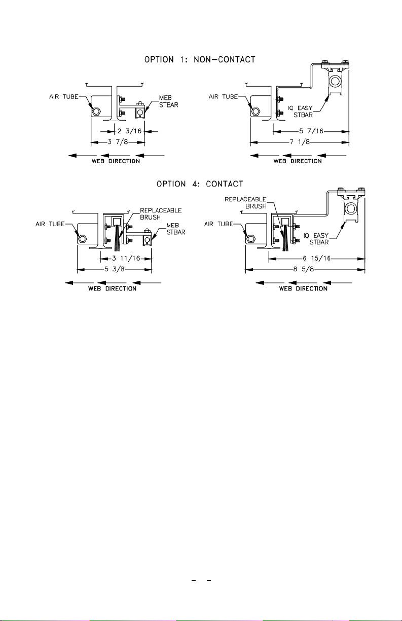
Vacuum hoods have two basic intake Options (see Figure 2):
Figure 2: Vacuum Hood Intake Options
Option 1 – Non-Contact
Simco-Ion’s static bars (IQ Easy or MEB) are used with a compressed air tube to
eliminate static charges on webs and other materials. Particles are subjected to an
aggressive blast of compressed air which lifts debris from the web. Debris is captured
and drawn into the vacuum system through the inlet. This intake configuration is
used on webs that cannot tolerate contact.
Typical applications include:
• Removal of slitting debris and static charges on plastic film.
• Removal of contamination and static charges during the converting process.
• Removal of contamination and static charges on film prior to adhesive
application.
Option 4 – Contact
Simco-Ion’s static bars (MEB or IQ Easy) are used with a compressed air tube to
eliminate static charges on webs and other materials. After the web is neutralized
it passes under a stiff bristle brush which loosens debris from the web. Particles are
then subjected to an aggressive blast of compressed air which lifts debris from the
5
Neutro-Vac 5200470 Rev B
web. Debris is captured and drawn into the vacuum system through an inlet. This
configuration is used in applications where web material can tolerate contact and
requires aggressive cleaning.
Dust Collectors
Simco-Ion’s standard line of dust collectors provide high efficiency, intermittent or
continuous-duty dust collection using either cartridge or bag filters. The cartridge
filter units use automatic shaking action to clean the filters each time the unit is shut
down. The continuous duty units use pulse jet airflow to purge the filters of dust.
The bag filter units require a manual shaking by the collector operator. All models
are acoustically lined inside the blower chamber for noise reduction.
Receipt of Equipment
1. Carefully remove the equipment from the packaging.
2. Inspect contents for damage that may have occurred during shipment. If any
damage has occurred during shipment, the local carrier should be notified at
once. A report should be forwarded to Simco-Ion, 2257 North Penn Road,
Hatfield PA 19440, (215) 822-6401.
3. Empty the packaging to ensure that small parts are not discarded.
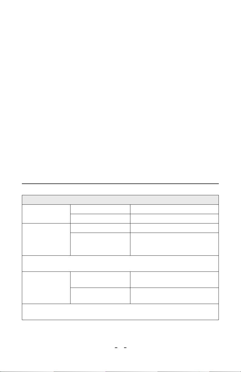
3. SPECIFICATIONS
Requirements
Vacuum System Vacuum Hood 1.2”of water
Volume 8 CFM per inch of intake slot (1/4”slot width)
Compressed Air
System
Pressure 5 psi minimum, 20 psi maximum
Volume
0.25 SCFM per inch of intake slot (at 5 psi)
0.50 SCFM per inch of intake slot (at 10 psi)
1.00 SCFM per inch of intake slot (at 20 psi)
NOTE: Compressed air must be clean and dry. Hoses and fittings must be of adequate size to
provide required airflow.
High Voltage
IQ Easy Static Bar Speed-T (24 VDC, 0.75A)
Hybrid-T (24VDC, 0.75A)
MEB Static Bar Power Supply F167 (120 VAC, 50/60 Hz, 0.25 A)
F267 (230 VAC, 50/60 Hz, 0.12 A)
NOTE: Maximum 2 static bars or 200” total static bar length can be used with power supply models
F167 and F267.
6
Neutro-Vac 5200470 Rev B
4. INSTALLATION
Hood Assembly Installation
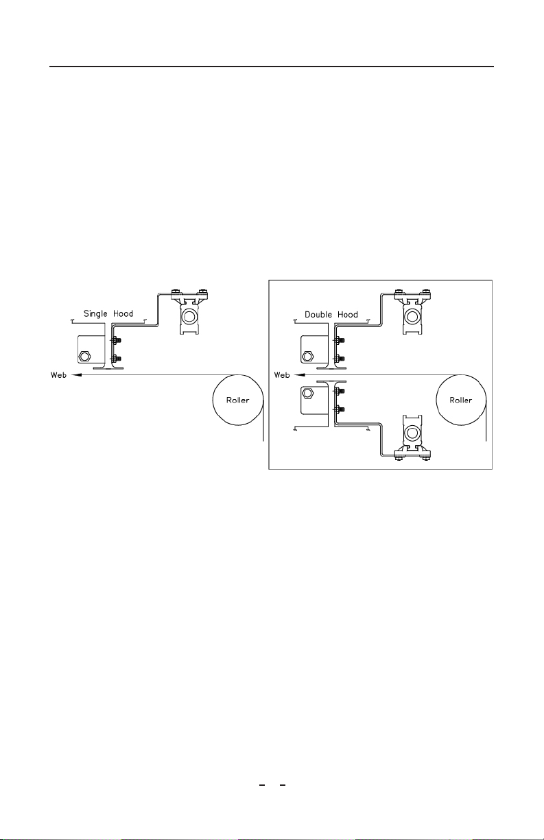
Locate hood(s) using the following guidelines:
• Locate near non-crowned (constant diameter) roller.
• Web must maintain a fixed location with respect to machine frame (i.e. not
near a take-up roller or a roller that swings).
• Web must maintain constant tension where the hood assembly will be
installed.
• Do not locate static bar(s) on the hood directly over a roller.
• Web must be in free air near static bar for the static eliminator to work (see
Figure 3).
Figure 3: Hood Locating
Contact a Simco-Ion customer service representative for assistance if you have any
questions on the proper location of the Neutro-Vac Hood assembly.
See Figure 3 to determine how to locate the hood so the web passes in the correct
direction. If your hood is not configured for proper installation, switch the
accessories:
1. Remove nuts securing mounting brackets to stud on intake slot.
2. Reverse order of accessories.
3. Replace nuts on studs to secure accessories.
To mount the hood use brackets or build a sturdy sub-frame that will center hood
over the web and allow adjustment of intake slot from 0” (touching web) to 1” from
web. Typical operating distance between the slot opening and web is 1/4” to 1/2”.
To accomplish this, hoods are supplied with brackets having slotted adjustment
holes. The overall dimensional drawing of your hood will provide you with the
dimensions needed for mounting and approximate hood weight.

7
Neutro-Vac 5200470 Rev B
The mounting frame must provide an electrical ground, or a separate ground
connection must be connected to ensure proper operation of the static bar.
Hood Adjustments
Option 1 – Non-Contact
Hood(s) should be set with intake slot 1/2” from web. Adjust hood height using
slotted holes in mounting brackets. At this distance, air bar pressure should be set
to 5 psi. If more aggressive cleaning is desired and web tension allows, set intake slot
1/4” from web and increase air bar pressure to 10 psi.
It may be necessary to increase hood-web distance or adjust the flow regulating
cutout for proper operation. Table 1 shows minimum and maximum air bar
pressure for different hood-web distances.
Option 4 - Contact
Hood(s) should be set with intake slot 1/4” from web. Adjust hood height using
slotted holes in mounting brackets.
Brush is mounted in a channel that may be moved up and down after loosening
its mounting nuts. Adjust the brush so it makes very light contact with the web.
Retighten mounting nuts.
At this distance, the air bar pressure can be set up to 20 psi for the most aggressive
cleaning
Vacuum System (Ductwork)
Each ductwork system is unique. The following are general guidelines for installation:
• Use the shortest possible length of flexible hose to connect the hood to the
vacuum system (typically 2’ length).
• Secure flexible hose with hose clamps.
• Use a flow regulating cut-out on each hook-up stub that connects to a hood
to allow each hood in system to be adjusted for air flow.
• Use rigid, smooth walled, galvanized pipe and fittings wherever possible to
provide smooth air flow and reduce vacuum losses in ductwork.
• Use long sweep elbows.
• Avoid using tees and short radius elbows because they produce unacceptable
vacuum losses.
• Use only ductwork recommended by Simco-Ion.
• Appropriate ductwork diameters are critical to airflow.
8
Neutro-Vac 5200470 Rev B
Ductwork Installation for All Units
CAUTION – Do not attempt to change the number or size of inlets. If the
dust collector is operated with more than the maximum permissible inlet
area, the motor and filters may become overloaded.
NOTE – When installing ductwork, use the shortest possible runs. Long
radius elbows and at least 45-degree branches. Avoid the use of airflow tees.
Ductwork should be of a proper size to permit passage of the air velocities
recommended for the material being collected. A complete selection of galvanized
steel pipe elbows, branches and fittings are available from Simco-Ion. Stainless steel
components are also available upon special order. If you require any assistance in
the design or selection of ductwork, contact your local Simco-Ion representative.
1. Connect piping joints with sheet metal screws, rivets or solder.
2. Wrap each joint with a single layer of duct tape. This will insure a rigid, airtight
system.
Power Supply for IQ Easy Static Bars
IQ Easy static bars are equipped with an integrated high-voltage power unit, ion
emitters and status LEDs. They require a 24 VDC supply voltage to be provided
via a 5-pin M12 connector. For detailed instructions, see the publication included
with the static bars.
Power Supply for MEB Static Bars
The following are brief instructions for power supplies used with the MEB static
bars. For detailed instructions, see the publication included with the power supplies.
1. Locate power supply where high voltage cable(s) from the static bar will reach.
2. Locate power supply where it is accessible but out of the way.
3. Do not cut high voltage cable(s) until everything has been mounted.
4. Orient / turn power unit so HV connection ports are facing downward.
The power supply is designed for flat surface mounting. It can easily be mounted
using flanges at the base of the unit. Proper grounding of the power supply is
essential for safe and efficient operation.
CAUTION – Electrical Shock Hazard
Failure to properly ground the power supply may result in an electrical
shock hazard to personnel and inefficient operation of the equipment. Do
not apply line power until all grounds and high voltage connections have
been completed.
Grounding the Power Supply for MEB Static Bars
There are three ways to ground the power supply:

9
Neutro-Vac 5200470 Rev B
Method 1
Power unit is equipped with a 3-conductor line cord. On power supplies designed
for 120 VAC operation, the line cord is fitted with a standard 3-prong plug and
should be plugged into a 3-terminal grounded receptacle. On power supplies
designed for 220 VAC operation, the AC line cord is not normally supplied with
the plug. The green wire provides the ground connection to the power supply and
should be connected to a true ground.
Method 2
Bolt power supply to a machine frame that is properly grounded.
Method 3
Connect the ground wire between ground lug on the power supply and a true
ground such as a cold-water pipe or grounded electrical conduit.
WARNING – Power supply should be connected to an AC/DC line that is
turned on and off with machine operation. This will ensure the high voltage
power supply is deactivated when the machine is off. If this is not possible,
the use of a separate, fused disconnect for the power supply is recommended.
Cable Routing (IQ Easy Bars)
For detailed instructions, see the publication included with the static bars.
Cable Routing (MEB)
The high voltage cables should not contact any grounded parts of the machine
frame. Cable supports are used to guide the high voltage cable from the static bar,
along machine frame and to the power supply. Cables should be kept at least 1/4”
away from:
• Machine frame
• Machine parts
• Walls
• Floor
To Install Cable Supports
1. Press split plastic bushing out of metal support and apply bushing to cable at
desired location.
2. Drill a 13/64” diameter hole through machine frame and mount the support.
3. Press bushing with cable back into support.
NOTE – Be sure that a cable support is positioned so that all strain and
motion from the cable where it enters the static bar and the power supply
is minimized.
10
Neutro-Vac 5200470 Rev B
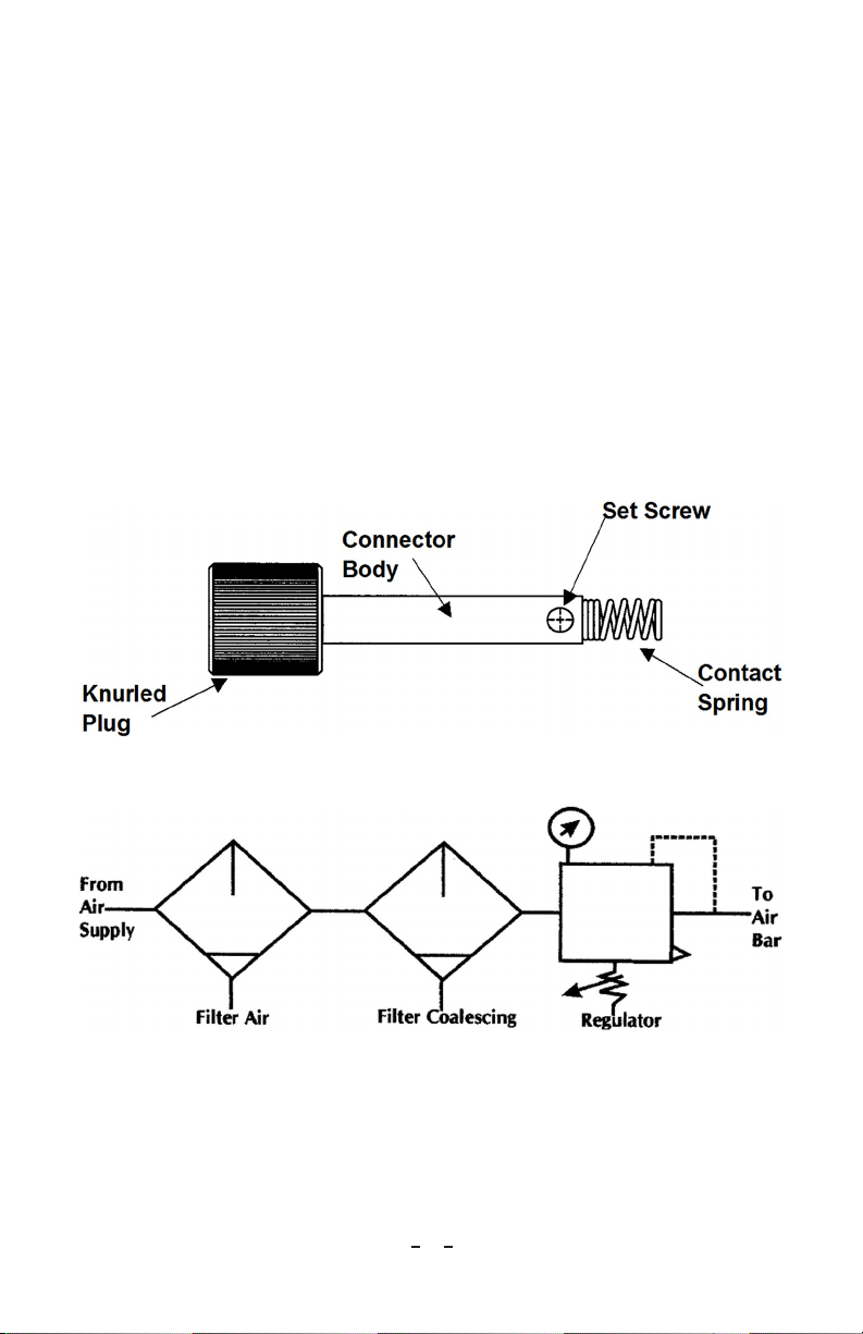
High Voltage Connector (MEB)
Attach a connector to the high voltage cable coming from each static bar. Allow
approximately 3” of additional cable on the connector before cutting.
1. Measure and strip 1/2” insulation from end of cable. Straighten conductor
strands.
2. Slide knurled plug onto cable with threaded end toward end of cable as shown
in Figure 4.
3. Slide connector body on cable with setscrew hole positioned toward end of
cable.
4. Slide high voltage connector over conductor until it butts against cable
insulation. Make certain all conductor strands are inside connector.
5. Line up set screw holes in connector body with high voltage connector. Insert
and tighten set screw. Pull firmly on connector body to make certain set screw
is well seated.
6. Screw contact spring (closed end first) onto high voltage connector
Figure 4: High Voltage Connector (MEB)
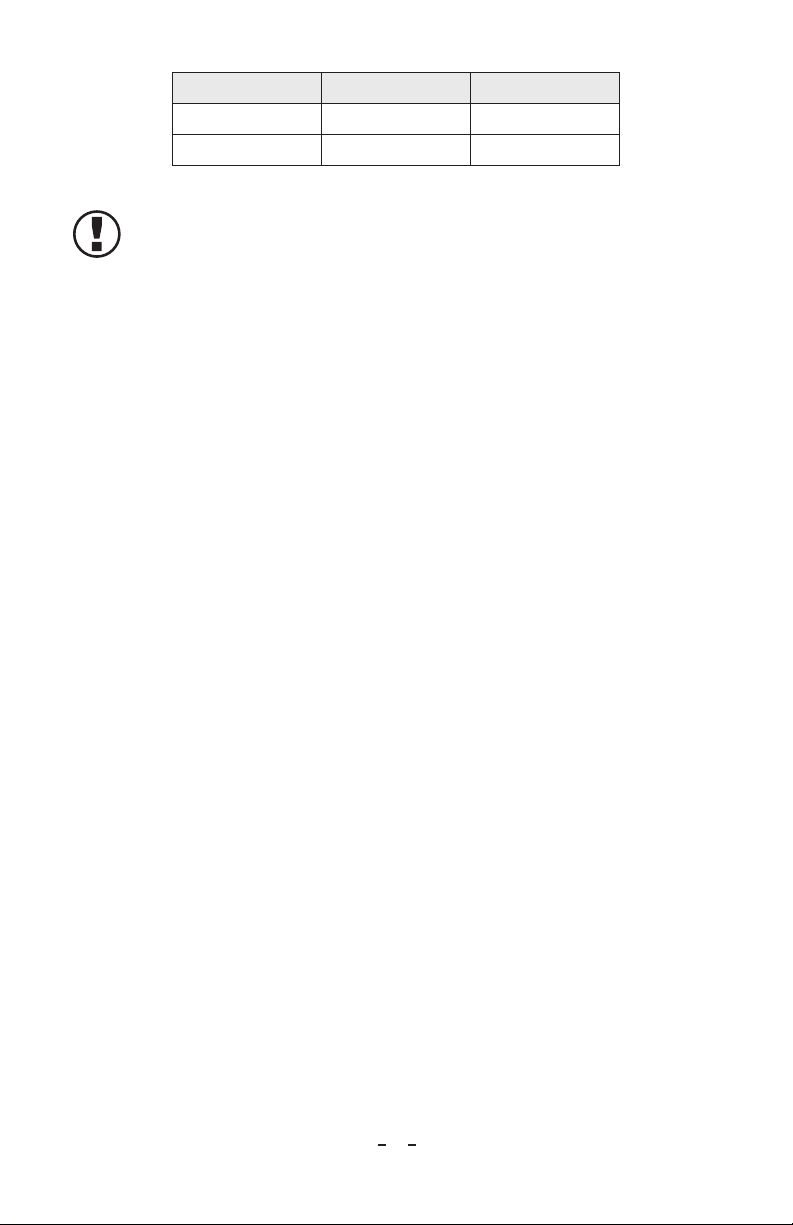
Air Bars
To determine the capacities of air preparation equipment needed for the Neutro-
Vac system, total the maximum SCFM needed by all air bars. See Section 2 -
Specifications for compressed air consumption. Use a 5-micron filter, coalescing
filter and regulator capable of operating down to 5 psi. Connect the components
as shown in Figure 5.
Figure 5: Air Bar Component Connection
The recommended tubing to hook up the air bars is polyethylene, polypropylene or
nylon with a minimum of 100 psi working pressure. This tubing is recommended
to provide a clean and safe connection between the air preparation components and
Neutro-Vac hood. Use Table 1 below to determine what size tubing and fittings
to use.
11
Neutro-Vac 5200470 Rev B
Pipe Size of Fitting I.D. of Tubing Air Bar Length
1/4 NPT 1/4” < 48”
3/8 NPT 3/8” > 48”
Table 1: Sizing Chart
NOTE – If the tubing or fitting is smaller than specified, airflow will be
restricted, and performance will be unacceptable.
Dust Collector Installation
DCX-500, DC550, DC1200, DC1500 and DC3000 Cartridge Style Collectors
Duct enters the dust collector through the cabinet inlet and then passes through a
tight mesh screen on the outside of the filter(s). The screen (spaced 1” away from
the filter media) catches fibrous dust while fine particles pass through the screen
and collect on the outside surface of the pleated filter cartridge. Clean air flows up
though the center of the filter cartridge into the blower then through the silencer
section of the cabinet. Clean air exits through the top clean air outlet.
DC66, DC75, DC84, and DC90 Bag Style Collectors
Dust laden air first enters through the dirty air inlet and then passes through the
cabinet where the dust is collected on the outside surface of the filter media. The
cleaned air then flows up through the center of the filter media and into the clean
air plenum. It enters the blower fan and exits through the blower exhaust located on
the roof of the cabinet dust collector (DC66, DC75 and DC84). The DC90 uses
an external motor/blower package so the exhaust is on the blower housing which sits
on top of the cabinet.
DC-aPJb Continuous Duty Collectors (a = # of horizontal columns of filters, b
= # of filters)
There is a separate instruction manual for these collectors. Basically, dust laden air
enters the top of the dirty air chamber. The debris settles to the bottom of the filter
cabinet in a hopper. The hopper normally fits over a 55-gallon drum into which the
debris may be dumped while the collector continues to operate. The drum may be
taken away from the area for cleaning while the collector continues to run, storing
debris in the hopper.
Debris will be seen on the outside of the filters, but it cannot penetrate the medium,
allowing it to be blown off the surface by a strong, reverse blast of air. The degree of
filter blockage is monitored so that the cleaning process is started at a pre-selected
point and ceases at a second pre-selected level.
The motor/blower package is mounted outside of the housing and may be fitted
with a silencing enclosure. (See manual #5200712 for Continuous Duty System.)
12
Neutro-Vac 5200470 Rev B
Dust Collector Installation for All Units
CAUTION – Dust collectors have a high center of gravity. Careful
handling is required to avoid overturning during moving. The collector
must be kept in the up-right position when moving or damage may occur.
WARNING – Fire Hazard
When dust collectors are used to collect explosive or fire risk dust, the dust
collector should be located outside the building. An individual familiar with
fire extinguishing equipment, flammable material hazards and local fire codes should
be consulted for recommendations and installation of the proper fire extinguishing
equipment.
WARNING – Explosion relief vents are required for some applications.
Consult with an insurance underwriter or a NFPA Manual (NFPA 68
Venting of Deflagrations - NFPA 91 Blower and Exhaust Systems) to
determine proper vent size and ratio. Vents installed on dust control
equipment within a building must be vented to the outside with ducting
that meets the following specifications:
• Cross section area no smaller than the vent
• No longer than 10’
• Straight with minimal bends (to minimize chances of secondary explosion)
• Fabricated from 16-gauge (or thicker) sheet steel
Consult the proper authority to determine proper methods of venting. Dust
collectors do not contain explosion relief vents.
Consult and comply with all National and Local Fire Codes and/or the appropriate
codes when determining the location and operation of dust collection equipment.
Place the dust collector as close as possible to the dust source in non-hazardous
applications.
NOTE – Various inlet sizes are available. Please specify size required at the
time of ordering your Neutro-Vac System. If unit is operated with more
than maximum permissible inlet area, the fan motor may become
overloaded or dust may settle within the ductwork due to low carrying
velocities.
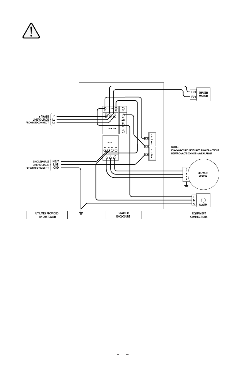
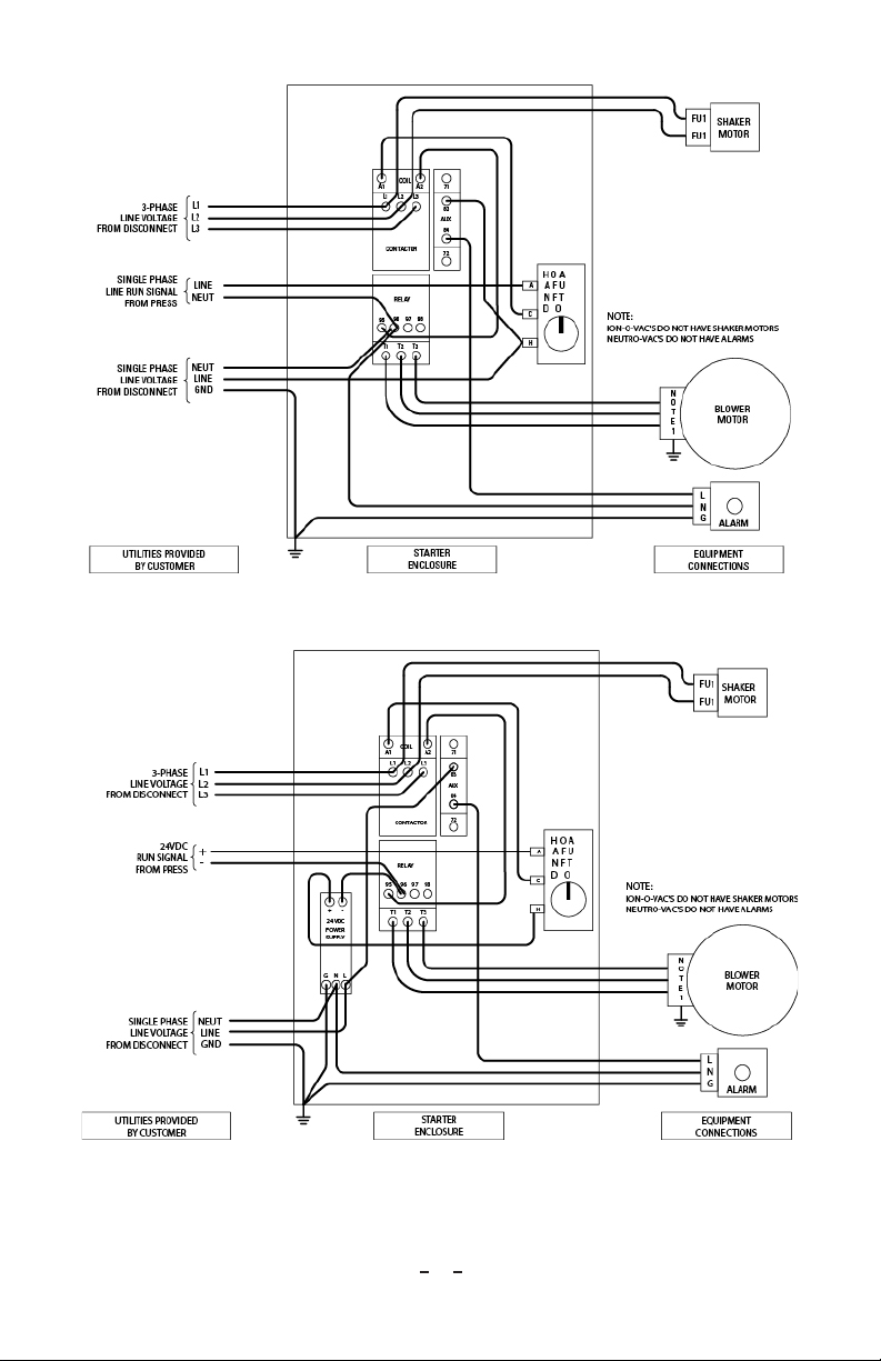
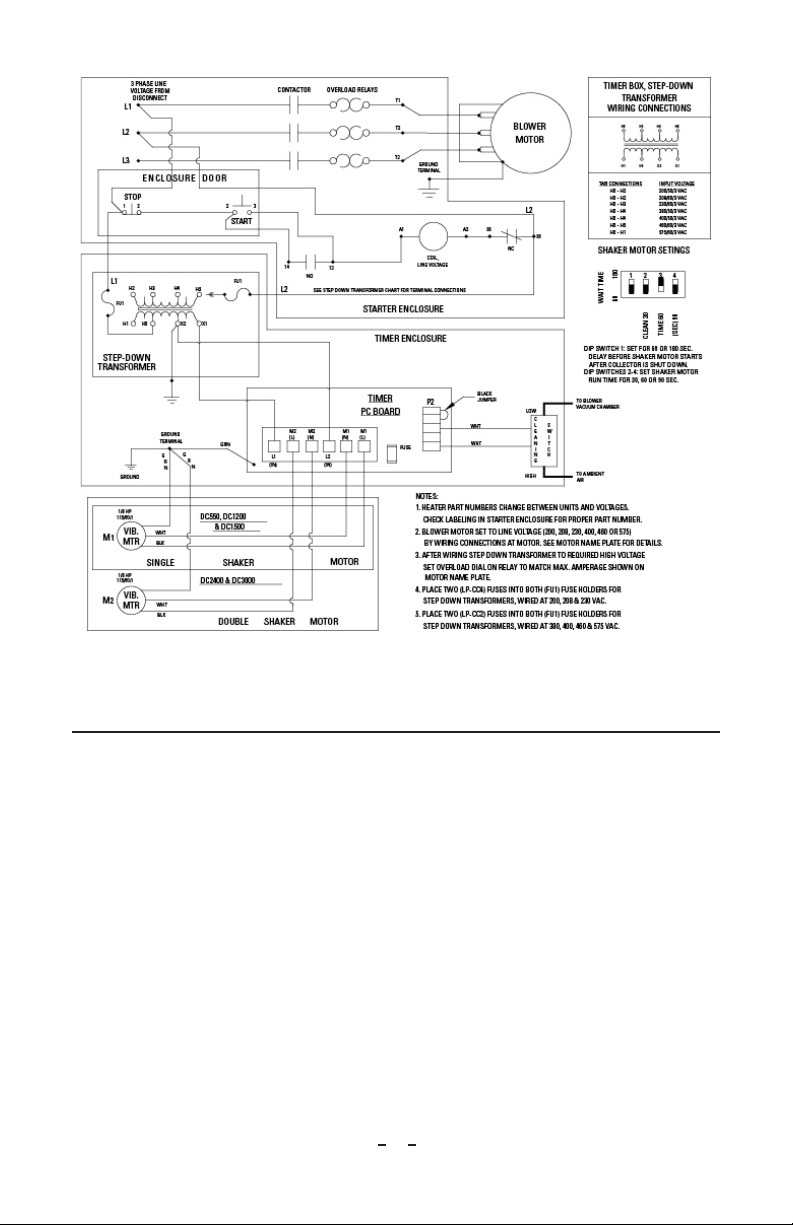
Electrical Installation
WARNING – A qualified electrician must perform all electrical work.
1. Make electrical connections to disconnect switch (customer-supplied), fan
starter, fan motor and control box (reference Figures 6, 7, 8, 9 & 10). See
electrical wiring diagram inside the control box cover (reference Figure 11). Fan
access is located through the top door of the cabinet.
13
Neutro-Vac 5200470 Rev B
WARNING – Verify that the air exhaust at the top of the collector is not
blocked. Verify that materials are not stored over the exhaust opening.
Stand clear of fan exhaust during rotation.
2. Start fan motor and visually verify that the blower wheel is turning in the
direction indicated by the rotation arrow on the blower housing. Incorrect
rotation direction will cause up to a 60% decrease in rated air volume while
requiring more than its rated horsepower. If the blower rotation is incorrect,
rotation must be corrected by switching any two leads (3 phase only).
Figure 6: Starter Enclosure Wiring With Push Button Start/Stop Switch
14
Neutro-Vac 5200470 Rev B
Figure 7: Starter Enclosure Wiring With Rotating On/Off/Auto Switch (120V Coil)
Figure 8: Starter EnclosureWiring (24VDC CoilWith PS)With Rotating On/Off/Auto Switch

15
Neutro-Vac 5200470 Rev B
Figure 9: Starter Enclosure Wiring (24 VDC Coil Without PS)With Rotating On/Off/Auto Switch
Figure 10: Starter Enclosure Wiring With Push Button Start/Stop Switch if Line & Coil Voltage are Equal
16
Neutro-Vac 5200470 Rev B
Figure 11: Wiring Connections
5. OPERATION
Verify
1. Hood is positioned properly over web.
2. Static bars are connected to power supply.
3. Power supply is properly grounded.
4. Air bar components are connected properly.
5. Air supply is clean and dry.
6. Ductwork to dust collector is installed properly.
7. Dust collector is in the most appropriate location for your application.
8. Exhaust outlets on dust collector are free of obstructions.
Start Neutro-Vac Web Cleaning System
1. Plug power supply into three-prong, grounded outlet.
2. Turn on air supply.
3. Plug dust collector into three-prong, grounded outlet.
4. Turn dust collector fan on.
17
Neutro-Vac 5200470 Rev B
6. MAINTENANCE
Neutro-Vac Hood Assembly
WARNING – Disconnect and lock out power to the Neutro-Vac Web
Cleaning System before performing all maintenance procedures unless
otherwise instructed. Turn off web drive equipment and remove web (if
possible) before performing maintenance.
Weekly
• Examine intake slot of Neutro-Vac hood for even in-draft of air.
• Remove any obstructions in intake slot.
NOTE – At regular intervals there are small spacers welded in place to
maintain the slot spacing. Do not remove the spacers.
• Examine air bar for even flow (if equipped).
• Examine brush for proper condition and contact with web (if equipped).
• Adjust brush for proper contact with web (if equipped).
• Examine hardware for security.
Monthly
• Wipe exposed surfaces.
• Remove debris from non-exposed surfaces using compressed air.
• Perform static bar cleaning procedure.
The static bar must be cleaned monthly to maintain optimal system performance.
The Static Bar Operation Test must be performed as needed and no less than
annually.
If bar is extremely dirty when cleaning, increase frequency to weekly. In very dirty
environments, it may be necessary to clean daily or at the end of each shift.
To Clean Static Bar
1. Using compressed air, blow out holes on both front and back of static bar. This
will remove dirt, dust and particulate collected inside bar.
2. Using a stiff nylon brush, scrub area around each pin, removing as much debris
as possible.
3. Use Isopropyl alcohol only (other solvents may damage plastic) applied with a
clean cloth to remove paint and ink build up.
CAUTION – Do not pour alcohol on bar or soak bar in alcohol at any time
or damage to the inner bar assembly may result.
4. Wipe off solvent using a clean rag.

18
Neutro-Vac 5200470 Rev B
WARNING – Do not hang rags on static bar or a fire may result.
5. Clean points using a stiff nylon brush.
Accessory Mounting
If it becomes necessary to remove the static bar, air bar, or brush for service, be sure
to replace it in the correct location relative to the web.
1. The MEB or IQ Easy Static Bar must be mounted with its points facing the web
and centered between mounting brackets. Secure the static bar with set screws
in the mounting bracket.
2. When replacing the air bar, holes must be pointed directly at the web
perpendicular to its surface). Secure the air bar with set screws in mounting
brackets.
Dust Collector Maintenance
WARNING – Disconnect and lockout power to the Neutro-Vac Web
Cleaning System before performing all maintenance procedures unless
otherwise instructed. Turn off web drive equipment and remove web (if
possible) before performing maintenance.
All Models
1. Empty collector drawer or drum when approximately two-thirds full.
2. Remove any dust settled at the bottom of the dust compartment on a weekly
basis.
3. Follow the manufacturer’s directions for motor maintenance. If your motor
requires servicing under the manufacturer’s warranty, contact an authorized
service center.
Table of contents


