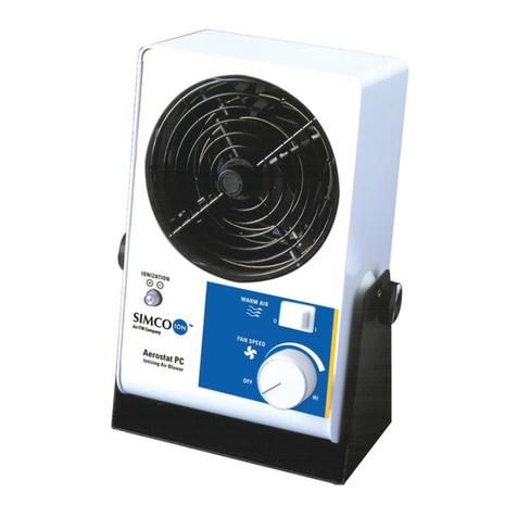
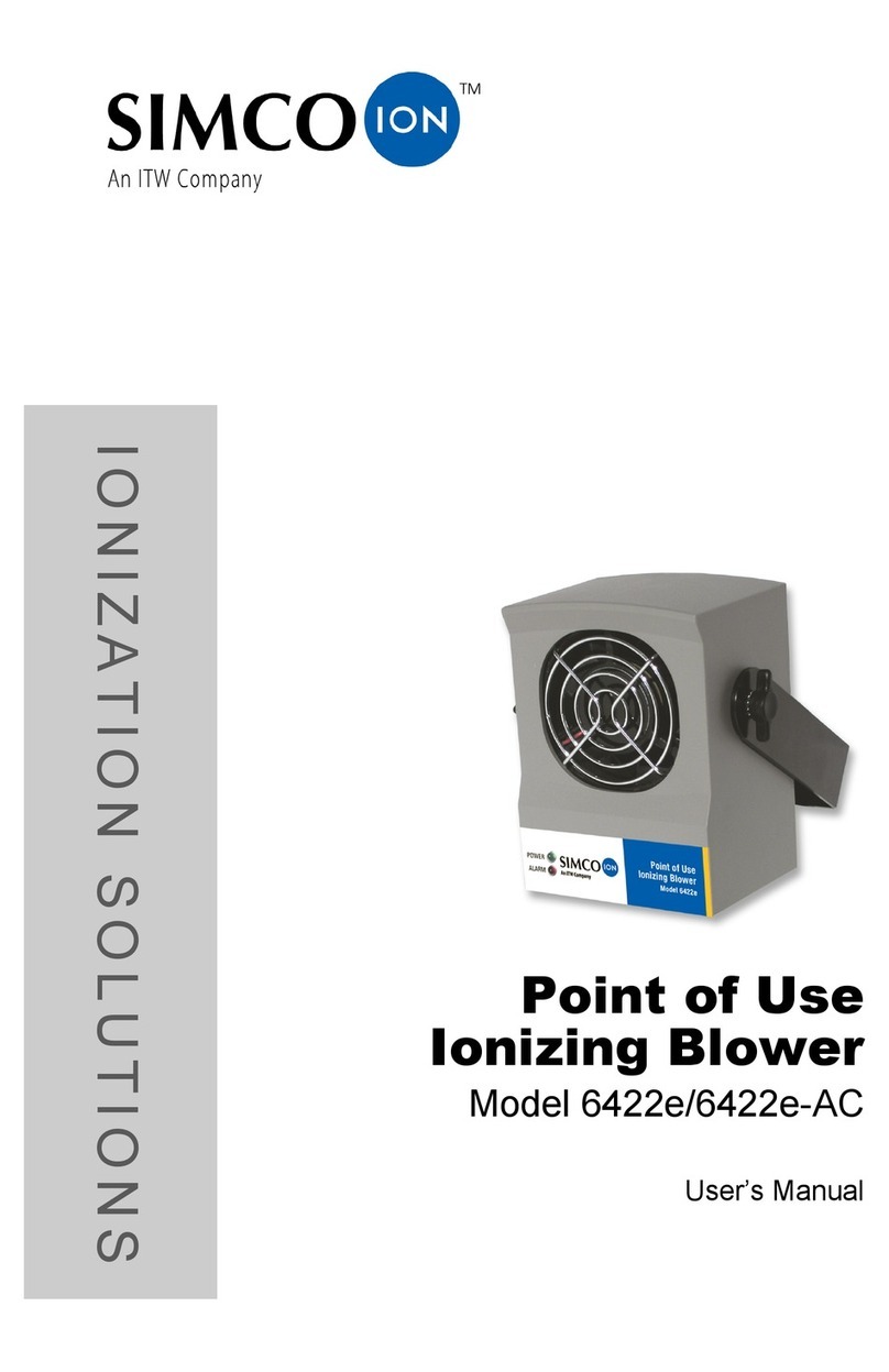
Simco minion2 Instruction Manual

INSTRUCTIONS
Operation/Maintenance
minION2™
Ionizing Air Blower
US Patents: 5,008,594,
6,717,792 B2, 6,785,114,
7,054,130
SIMCO's minION2 ionizing air blower is designed to control electrostatic
charges in semiconductor and electronics manufacturing equipment and
for benchtop applications requiring high performance in a small pack-
age. Using steady-state DC corona ion technology, the minION2 fea-
tures self-monitoring to ensure controlled, consistent ion output.
SECTION 1 Description
SECTION 2 Safety
SECTION 3 Features
SECTION 4 Specifications
SECTION 5 Installation
SECTION 6 Operation
SECTION 7 Maintenance
SECTION 8 Replacement Parts
SECTION 9 Warranty
2257 North Penn Road
Hatfield, PA 19440
(215) 997-0590
(800) 538-0750
Fax: (215) 997-3450
Publication 5200964
(Rev B, February 2007)
2257 North Penn Road
Hatfield, PA 19440
Phone: (215) 997-0590
(800) 538-0750
Fax: (215) 997-3450
http://www.simcoION.biz
e-mail: [email protected]
®
®

SECTION 1 Description
SIMCO’s minION2 ionizing air blower is designed to control electrostatic
charges in semiconductor and electronics manufacturing equipment and for
benchtop applications requiring high performance in a compact package. The
minION2’s small size also makes it easily portable for field service applications
where static control is necessary.
Using steady state DC corona ion technology, the minION2 features self-moni-
toring to ensure controlled, consistent ion output. Performance is enhanced by
SIMCO’s patented radial emitter array and ion balance maintained with the
patented ionizing circuitry. Structured airflow from the patented air outlet
ensures maximum delivery of ionized air to the target. These features in the
design of the minION2 enable it to meet the demands of critical semiconductor
equipment manufacturers with corona ionization.
The minION2 uses modular wiring to enable “daisy chaining” of units, up to
three units may be daisy chained on a standard power supply. A plug-type ter-
minal block is included for easy wiring if the user desires to hard-wire the unit
in place. There is the option of supplying power to the unit through the terminal
block where the user wishes to supply power from a 24 VDC machine bus. The
terminal block also features relay contact output of the unit’s fault alarm for
remote fault sensing.
An optional clamp-on spring arm stand is available for benchtop applications
requiring elevated positioning, or for locations with a restricted mounting surface
area.
SECTION 2 Safety
CAUTION!
1. Read the complete Operation Manual before operating. Failure to follow
instructions may result in damage to the ionizer and/or personal injury.
2. The AC adapter is supplied with a 2- or 3-prong inlet plug, which must be
inserted into an appropriate, properly wired wall outlet.
3. A factory-qualified service technician must perform component service and
repairs. Please contact SIMCO Customer Service for information.
WARNING!
4. Keep the unit dry. Do not operate the unit in flammable or explosive
atmospheres.
5. Do not insert objects through the unit's intake or outlet grilles while in
operation. Damage to the ionizer and/or personal injury may result.
SECTION 9 Warranty
SIMCO warrants its products to be free of defects in components, workmanship,
or materials for a period of one year from date of purchase. This warranty does
not apply to any physical or electrical damage caused by misuse, abuse or negli-
gence (such as any modifications made to the unit or service work done by any
other than SIMCO authorized technicians). Any unit with altered or removed
serial number is ineligible for warranty.
SIMCO will not be liable for loss or damage due directly or indirectly to an
occurrence or use for which the product is not designed or intended. In no event
shall SIMCO be liable for incidental or consequential damages except where
state or regional laws override.
This warranty extends to the original purchaser and is not transferable. No per-
son, agent, distributor, dealer or company is authorized to change, modify, or
amend the terms of this warranty in any manner whatsoever.
All products returned must have an “RA” (Return Authorization) number regard-
less of warranty status. Call SIMCO for an assigned RA number.
Information in this document is subject to change without notice and does not
represent a commitment on the part of SIMCO. No part of this manual may be
reproduced or transmitted in any form or by any means, electronic or mechani-
cal, including photocopying and recording, for any purpose other than the pur-
chaser’s personal use without written permission of SIMCO.
29

SECTION 8 Replacement Parts/Part Numbers
Part Number Description
4011424 minION2 (no power supply)
4011425 minION2 (with 100/120VAC Japan / North America power
supply)
4011426 minION2 (with 230VAC Continental Europe power supply)
4011427 minION2 (with 230VAC United Kingdom power supply)
5051406 minION2 power supply only (100/120VAC Japan / North
America)
5051407 minION2 power supply only (230VAC Continental Europe)
5051408 minION2 power supply only (230VAC United Kingdom)
4371099 emitter, standard stainless steel (6 required)
4370760 emitter, long life tungsten (6 required)
4520764 modular cable, 4P4C, 3’ long
4520767 modular cable, 4P4C, 6’ long
5051141 articulated arm kit
SECTION 3 Features
• Small and compact
• Closed –loop balance control
• Simple to install and operate
SECTION 4 Specifications
OPERATING SPECIFICATIONS
(Balance) Offset Voltage: 0+/-10 V
Discharge time in seconds:
Distance 305 mm 460 mm 610 mm 760 mm 915 mm
(12 in.) (18 in.) (24 in.) (30 in.) (36 in.)
Fan - High 2 sec. 3 sec. 5 sec. 7 sec. 9 sec.
Fan - Low 3 sec. 4 sec. 7 sec. 9 sec. 12 sec.
Offset voltage and discharge time determined as per ANSI/ESD STM3.1 using 6”
x 6”, 20 pF plate (charged plate monitor). Discharge times are in seconds from
1000 volts to 100 volts.
Input Power: 24 VDC, 250 mA, 6W
Power Supply: Universal 100-240 Vac input (IEC320) / 24 Vdc, 750
mA output, suitable to power up to 3 units.
Operating Temperature: 0˚C to 50˚C (32˚F - 122˚F)
Airflow Volume: Fan - High: 42 CFM (1.2 m3/min)
Fan – Low: 21 CFM (0.6 m3/min)
Audible Noise: 52 dB(A) at 610mm (24 in.)
48 dB(A) at 1m (39 in.)
High fan speed, measured perpendicular to air outlet.
ON/OFF: Switch
Fan Speed: Variable, recessed adjustment.
Indicators: Power: green LED, Fault: red LED.
Connectors: Two 4-position, 4-contact (4P4C) modular “handset”
connectors for power, may also be used for daisy
chaining units. Modular cable is included with unit.
Modular connector part numbers: (Amp 5-641334-3,
Hirose TM3P-44P, Kobiconn, 154-UL6164)
3 8

Connectors: Plug type terminal block may be used for power
and/or faultoutput connection. Terminal block is
included with unit. Terminal block part numbers:
(Weidmuller 1792890000, Phoenix 1803604,
Altech 36.305)
MECHANICAL SPECIFICATIONS
Emitter Material: Polished stainless steel
Enclosure Material: Reinforced polycarbonate, color: white
Enclosure Dimensions: (98mm W x 136mm H x 60mm D)
3 7/8” W x 5 3/8” H x 2 3/8” D
Unit Weight: (0.5 kg) 1.1 lb
Stand Material: Nickel plated stainless steel
SECTION 5 Installation
5.1 Unpacking
Carefully remove the equipment from the carton and inspect the contents.
NOTE: If any damage has occurred during shipment, notify the local carri-
er at once. A report should also be forwarded to SIMCO, 2257 North Penn
Road, Hatfield PA 19440. See Section 9 (Warranty) for Return Shipment
information.
5.2 Installing
The minION2 ionizer is designed for portable or permanent operation. Typically,
the unit should be positioned such that there is good airflow provided to the crit-
ical area. Generally this requires that the unit be within 36” inches of the intend-
ed target. The stand provided can be used in a permanent operation by bolting it
to a sturdy flat surface such as a wall or shelf. The unit can be mounted hori-
zontally if required.
CAUTION!
5.3 Electrical Connections
The standard AC adapter provided with the minION2 is a universal input AC
type adapter with a line cord suitable for the region of operation. This AC
adapter may be used to power up to three minION2 ionized air blowers by wiring
them in series (daisy chain fashion) with the modular cords included. The con-
nectors used on the minION2 are 4P4C modular “handset” style connectors. For
reference, the modular cable carries +24 VDC on the inner two conductors and
7.3 Ion Output and Balance Check
To test the unit for ion output, the use of a charged plate monitor is recommend-
ed. Prior to performing these checks, clean the emitters as described above and
allow the unit to run for 10 minutes to allow the ion balance to stabilize. Offset
voltage and discharge times can be measured and checked against the Ion
Balance and Ion Output tables in Section 4, Specifications. If a charged plate
monitor is not available, periodic verification instrumentation may be used but if
periodic verification instruments are used it will be necessary to get “baseline”
data using the chosen periodic verification instrument.
7.4 Emitter Replacement
To replace emitters, turn off the minION2 and unplug it from the power supply
at the rear panel connector. Lay unit face down on a soft surface. Remove the
four Philips head screws at the air inlet on the rear panel. Lift the rear panel out
of the enclosure and set to one side (Note how the black plastic divider fits
between the ionizer and circuit boards during disassembly). The ionizing hub
contains sockets for the ion emitting pins. Carefully remove the ion emitters by
pulling them straight out from the ionizer hub. Push new ion emitters into the
sockets, make sure all sockets have emitters and all emitters are fully inserted
into their sockets. Replace the rear panel on the enclosure while guiding the
black plastic divider back into place. Ensure that the power switch and power
jacks are properly fitted through the openings on the rear panel. Secure the rear
panel with the four Philips head screws, do not over tighten the screws. Test unit
and return to service.
7.5 Troubleshooting / Diagnostics
This information provides a quick troubleshooting reference for the minION2
ionizing air blower. Should any of these possible solutions not solve the problem,
contact SIMCO.
47
PROBLEM CAUSE SOLUTION
UNIT FAILS TO OPERATE AC ADAPTER NOT CONNECTED CHECK ALL ELECTRICAL
(NO GREEN INDICATOR CONNECTIONS
LIGHT) FAULTY AC ADAPTER REPLACE AC ADAPTER
UNIT FAILS TO OPERATE INTERNAL FAULT RETURN UNIT FOR REPAIR
(GREEN INDICATOR
LIGHT ON)
RED FAULT INDICATOR DIRTY EMITTER HUB CLEAN EMITTER HUB AS
ILLUMINATES DESCRIBED ABOVE
INTERNAL HV FAULT RETURN UNIT FOR REPAIR
EXCESSIVELY LONG DIRTY EMITTERS CLEAN EMITTERS AS
STATIC DISCHARGE TIMES DESCRIBED ABOVE
WORN EMITTERS REPLACE ION EMITTERS
ION BALANCE OUT OF DIRTY EMITTERS CLEAN EMITTERS AS
SPECIFICATION DESCRIBED ABOVE
WORN EMITTERS REPLACE ION EMITTERS
GROUNDED METAL NEAR MOVE METAL AWAY FROM
IONIZED AIR OUTLET OUTLET OR MOVE OUTLET
AWAY FROM METAL

ground/return is on the outer two conductors.
The minION2 may also be powered through the plug type terminal block locat-
ed on the rear panel; +24 VDC goes to pin 1 and the ground/return goes to pin 2.
This allows powering of minION2 ionized air blowers from a 24 volt machine
bus. Each minION2 draws 250 milliamps so adequate current must be provided.
A unit powered through the plug type terminal block may power other minION2
units wired in series (daisy chain fashion) with the 4P4C modular cords includ-
ed. Power distributed through the modular cable must be limited to a maximum
of 2 amps for safety purposes. Wired in this fashion, the recommended maxi-
mum number of units wired in series is 5.
The plug type terminal block also provides relay contact output for the fault
alarm. Pin 4 is Common. Pin 5 is Normally Open. Pin 3 is Normally Closed.
The relay contacts are rated for a maximum of 1 A at 30 Vdc resistive with a
maximum switching voltage of 220 VDC.
A terminal block plug is supplied with the minION2.
SECTION 6 Operation
The minION2 power switch is located on the rear panel of the unit, above the
modular cable jacks. The rear panel also has a small hole next to the modular
cable jacks that provides access to the recessed fan speed control adjustment.
The fan speed may be adjusted with a small screwdriver or trim pot tool.
Clockwise rotation provides maximum fan speed, counterclockwise provides
minimum fan speed.
The front panel of the minION2 has two LED indicator lights. The green LED
indicates the unit is powered. The red LED is a fault indicator for the high volt-
age power supply monitoring circuit. The high voltage power supply monitor-
ing circuit also drives the fault alarm relay.
The minION2 produces an ionized air stream that covers a targeted area. The
time required to neutralize a static charge on an item in the target area depends
on several factors. Two important factors are; distance to ionizer and air veloci-
ty. Set the fan speed as high as acceptable to provide more rapid static neutral-
ization. For fast neutralizing, the minION2 should be as close to the target area
as practical.
SECTION 7 Maintenance
7.1 Emitter Cleaning
To clean emitters, turn off the minION2 and unplug it from the power supply.
Visually inspect the emitter array for particle or dust accumulation. Moisten a lint
free swab with deionized water or isopropyl alcohol and insert it through the inlet
grille. Wipe each emitter clean and clean the emitter hub as necessary to remove
accumulation. Allow to evaporate completely before returning the minION2 to
service.
7.2 Air Inlet and Outlet Cleaning
The air inlet grille on the rear of the unit and the ionized air outlet should remain
clean to prevent restriction of air flow. They can be cleaned with a soft brush or
vacuum.
5 6
Table of contents
Other Simco Blower manuals
