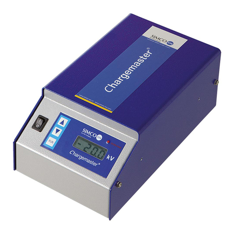
Simco CM5 User manual

CM5_UM_ 9752090319_GB_V0_9 1 / 67
CM5
DC High-Voltage Generator
SIMCO (Nederland) B.V.
PO Box 71
7240 AB Lochem, the Netherlands
Telephone+31-(0)573-288333
Fax +31-(0)573-257319
Internet http://www.SIMCO.nl
Apeldoorn trade register no. 08046136

CM5_UM_ 9752090319_GB_V0_9 2 / 67
USER MANUAL FOR CM5
CONTENTS
Preface ........................................................................................................................................4
Explanation of symbols.............................................................................................................4
1Introduction.........................................................................................................................5
2Description and operation .................................................................................................5
2.1Operating modes ............................................................................................................6
2.2Operational modes..........................................................................................................6
2.3Menu...............................................................................................................................7
2.4Activation of the high voltage ..........................................................................................7
2.5Serial communication bus module (optional) ..................................................................7
3Safety ...................................................................................................................................8
4Technical specifications ....................................................................................................9
5Installation.........................................................................................................................12
5.1Prior check....................................................................................................................12
5.2Overview.......................................................................................................................12
5.3Installing the CM5 .........................................................................................................12
5.4Rotating the front panel 180° ........................................................................................14
5.5Connecting the CM5 .....................................................................................................15
5.6External control signals.................................................................................................15
5.7Switching the high voltage on and off externally (Remote HV on/off) ...........................15
5.8Analogue control signals...............................................................................................16
5.8.1Analogue control signal Remote Voltage Setpoint/Voltage Limit ...............................16
5.8.2Analogue control signal Remote Current Limit/Current Setpoint ...............................17
5.9Analogue readout signals..............................................................................................17
5.9.1Analogue readout signal Remote Output Voltage......................................................18
5.9.2Analogue readout signal Remote Output Current......................................................18
5.10Internal 12 V supply voltage ......................................................................................19
5.11Digital status signals .................................................................................................. 19
5.11.1Operating signal .....................................................................................................19
5.11.2Pin 9 output select: limit alarm/arc detect...............................................................19
5.12External bus supply voltage.......................................................................................20
6Commissioning................................................................................................................. 21
6.1Switching the mains voltage on/off................................................................................ 21
6.2Configuring the generator via the ‘Initial setup’ (Quick Init) menu................................. 21
6.2.1CM5 as a replacement for a regular ECM. ................................................................22
6.2.2CM5 with Anybus module (optional). .........................................................................22
6.2.3CM5 in Local mode, Remote mode or AdvOutC mode (optional).............................. 23
6.3Unlocking the locked menu........................................................................................... 24
6.4The main menu .............................................................................................................24
6.5Key functions ................................................................................................................25
6.6Displaying the current Voltage setpoint/current............................................................. 26
6.7Changing the Voltage setpoint/current..........................................................................26
6.8Keyboard lock ...............................................................................................................26
6.9RunButton mode ...........................................................................................................27
6.10Entering a user password .......................................................................................... 27
6.11Menu screens ............................................................................................................27
6.12Remote control ..........................................................................................................28
6.13Fieldbus control (only if an Anybus module has been installed and activated) .......... 28
6.14External switching of the high voltage of the generator (Remote HV on/off).............. 28
6.15Limit LED indicator.....................................................................................................29
6.16Operating signal ........................................................................................................29
6.17Pin 9 output as Limit Alarm signal .............................................................................29

CM5_UM_ 9752090319_GB_V0_9 3 / 67
6.18Pin 9 output as Arc Detect signal............................................................................... 29
6.19"Rectifying the "Too many ARCs error!” ....................................................................29
6.20Switching arc detection protection on/off ...................................................................30
6.21Restoring the factory settings ....................................................................................30
6.22Restoring the user password .....................................................................................30
6.23Quick init menu structure ........................................................................................... 31
6.24Menu structure........................................................................................................... 33
7Functional check...............................................................................................................49
8Maintenance ......................................................................................................................50
9Faults .................................................................................................................................50
10Repairs ............................................................................................................................53
11Disposal ..........................................................................................................................53
Spare parts ...............................................................................................................................53
Appendix IFactory settings (after resetting) ..................................................................54
Appendix IIStandard settings (as replacement for an ECM)..........................................55
Appendix IIIStandard settings (CM5 with Anybus module).............................................56
Appendix IVOperating signal...........................................................................................57
Appendix VConnector connections ................................................................................58
Appendix VIQuick Init installation configuration examples ..............................................60
Appendix VIIExamples - Changing the existing CM5 configuration .................................62
Appendix VIIIAdvanced Current Control (optional) ........................................................... 65
Appendix IXAdvanced Output Control (optional).............................................................66
Appendix XFactory password ........................................................................................67
Appendix CM5 interface description (depends on the supplied bus module)

CM5_UM_ 9752090319_GB_V0_9 4 / 67
Preface
This manual describes the installation and usage of the CM5. Any mention of a generator
elsewhere in this user manual refers to the CM5. Charging bars and charging electrodes are
referred to in this user manual as charging electrodes.
A symbol or text in square brackets [ ] indicates an operating button on the generator. Text in
quotation marks (" ") indicates text on the generator display.
This manual must be available at all times to staff operating the equipment.
Read through the entire manual before installing and using the product.
Follow the instructions set out in this manual to ensure proper operation of the product and to
retain your entitlement under the guarantee. The terms of the guarantee are set out in the
SIMCO (Nederland) B.V. General Terms and Conditions of Sale.
Explanation of symbols
Warning
Indicates special information to prevent injury or significant damage to the
product or the environment.
Attention
Important information for making the most efficient use of the product
and/or for preventing damage to the product or the environment.

CM5_UM_ 9752090319_GB_V0_9 5 / 67
1 Introduction
The CM5 is a high voltage generator that is used to supply SIMCO charging bars/electrodes
with a high voltage. This combination is called the CM5 electrostatic charging system. It is used
to bond materials temporarily.
The generator can either be operated manually or remotely (analogue or digital). Due to the
digital bus the generator can be used in a serial network.
On the front of the generator there is an on/off switch, a display for displaying system settings
and information, six operating buttons (touch keys) for setting the high voltage or operating the
user interface and a limit LED to indicate that the output voltage or supplied current is limited.
On the back are the mains input, the high voltage connections, the serial bus or network
module, connections for analogue operation and for switching the high voltage on and off
remotely.
Figure 1: front and backside of the CM5
2 Description and operation
Description
Once the mains voltage has been connected and the generator has been switched on, it will
generate a stabilised high voltage. The output voltage and current can be controlled from the
generator and these are short-circuit protected. A keyboard is used to operate the generator.
Information about the generator is shown via a display. This display shows information about
the currently measured high voltage and current at the output, but also information such as the
high voltage and current settings, operational modes and various generator settings. The
generator has analogue and digital connections, making it possible to remotely operate the
generator. The generator is protected against overload, whereby in the event of an overload the
high voltage output will be limited. If the limit LED lights up, the generator is limited.
Figure 2: front panel of the CM5

CM5_UM_ 9752090319_GB_V0_9 6 / 67
2.1 Operating modes
The generator has a number of different operating modes:
Local mode The high voltage or output current of the generator is set using the
keyboard.
Remote mode The high voltage or output current of the generator is set and read
via external analogue control signals.
Fieldbus mode (Optional) The high voltage or output current of the generator is set
and read via a serial communication interface.
AdvOutC mode (Optional) Advanced Output Control mode. In this mode the high
voltage that is set depends on an analogue control signal, e.g. speed
control of the machine (see Appendix IX).
By using the generator's integrated menu structure, it is possible to switch between the various
operating modes.
Locked mode
If operating in local mode it is possible to (temporarily) lock the operation. This is called ‘locked’
mode. In this mode it is no longer possible to change the output voltage or output current using
the keyboard.
2.2 Control modes
The generator has different ways of controlling the output voltage and current. The generator
can be switched to VC/CV mode or CC mode.
VC/CV mode Voltage Control or Constant Voltage. The generator will maintain the
set voltage value and the current to be supplied by the generator will
be adjusted to this.
CC mode Current Control or Constant Current. The generator will maintain the
set current value and the output voltage to be supplied by the
generator will be adjusted to this.
AdvCC mode (Optional) Advanced Current Control mode. The generator operates
in an intelligent CC mode, with the ability to switch back to the stand-
by state when no object is present below the connected electrodes
(see Appendix VIII).
Operation in Voltage Control mode
When the generator is operating in the VC mode, the desired output
voltage is set on the generator. The generator now maintains the
set output voltage and, depending on the load, adjusts this with a
larger or smaller current. The charging current decreases, however,
if the electrodes become dirty.
Figure 3: Voltage Control mode

CM5_UM_ 9752090319_GB_V0_9 7 / 67
Operation in Current Control mode
When the generator is operating in the CC mode, the desired
current is set on the generator. The generator now maintains the
set current and adjusts this with a higher or lower output voltage.
This method of control results in a constant ion current, or constant
charging.
Figure 4: Current Control mode
2.3 Menu
Various generator settings can be changed via the menu. This is done by using various key
combinations or by configuring the various parameters. This advanced menu consists of main
menus and submenus. Access to this menu can be protected with a user password.
2.4 Activation of the high voltage
The generator is able to switch the high voltage on and off using an external switch signal. This
is the Remote On/Off control.
Cont or Continuous The HV output voltage is continuously present at the output of the
generator.
Ext or External The HV output voltage is switched on and off via an externally connected
switching signal.
Bus The HV output voltage is switched on and off via information in the serial
communication protocol.
2.5 Serial communication bus module (optional)
Installing an Anybus module means that the generator can be operated by a serial bus. In order
to be able to communicate with a generator in the communication network that is switched off,
an external supply voltage must be connected. The choice of serial communication protocol
used is determined by the Anybus module that is installed.

CM5_UM_ 9752090319_GB_V0_9 8 / 67
3 Safety
The following safety guidelines must be observed in order to prevent physical injury and
damage to objects or to the generator itself.
Warning:
- Electrical installation must be carried out by a skilled electrical engineer according to the
applicable national and local regulations.
- The equipment must be properly earthed. Earthing is required to ensure safe and proper
operation and to prevent electrical shocks upon contact.
- Do not touch any live parts.
Otherwise you will receive a dangerous electric shock!
- Disconnect the power supply before carrying out work on the unit.
- Only use the generator in combination with suitable SIMCO bars/electrodes.
- Keep the generator free of dirt, dust and moisture in order to ensure its safe operation.
- High voltages are dangerous, especially for people with a pacemaker.
- Do not use the CM5 in an environment where there is a risk of fire or explosion.
- Do not expose the CM5 to vibrations and knocks.
- The equipment may only be repaired by SIMCO employees.

CM5_UM_ 9752090319_GB_V0_9 9 / 67
4 Technical specifications
Required power supply:
Supply voltage 100–240 V AC
Supply voltage limit values 85–264 V AC
Frequency 50–60 Hz
Frequency limit values 47–63 Hz
Current power Max. 240 W
Connection Euro connector IEC-320
Fuse (rear): 3.15 AT
Output:
CM5 30N (30P) CM5 60N (60P)
Max. output voltage 30 kV DC 60 kV DC
Max. output current 5 mA 2.5 mA
Max. output power 150 W 150 W
High voltage connection 4x spring connector 4x spring connector
Voltage stabilisation 2% of max. output voltage
Load stabilisation 2% of max. output voltage
Output voltage Can be set between 0 kV and max. output voltage
Ripple, peak-peak 5% of max. output voltage at maximum load
User interface:
Operation 4x cursor keys, ESC key and key
Limit indicator Red LED
Display 4x 20 character LCD with background lighting
Accuracy 5% of the maximum voltage ± 2 digits
Digital I/O:
Bus module 1x Anybus connector. The Anybus module is optional.
For the available networks and protocols, contact
SIMCO (Nederland) B.V. or your local representative
Additional options - Switching the high voltage on/off
- Readout of the output voltage (absolute and
percentage values)
- Readout of the output current (absolute and
percentage values)
- Setting the output voltage or current (absolute and
percentage values)
- Setting the maximum output current or voltage
I/O analogue (via the 25-pin sub-D
connector):
External bus supply voltage input Specification:
10 V DC, 0.5 A max / 27 V DC, 0.2 A max.
Remote HV on/off input 0 V = off, 10-30 V = on (typically 12 V)
Specification:
10 V DC, 10 mA min / 30 V DC, 25 mA max.
Status indicators (Operation and Limit
Alarm/Arc Detect)
30 V DC, 10 mA max.
Analogue control voltage Specification:
0–5 V DC or

CM5_UM_ 9752090319_GB_V0_9 10 / 67
0–10 V DC or
0–20 mA DC or
4–20 mA DC.
Analogue readout voltage Specification:
0–5 V DC or
0–10 V DC or
0–20 mA DC or
4–20 mA DC.
Control voltage output:
12 V output voltage 12 V DC ± 20% 20 mA max.
Environment:
Use Industrial, internal use
Temperature 0–55°C
Installation Dust-free and vibration-free
Protection class IP20
Mechanical:
Dimensions CM5 30N (30P) CM5 60N (60P)
Length (incl. high voltage connector) 340 mm 388 mm
Width 272 mm 272 mm
Height 108 mm 108 mm
Weight 8.2 kg 8.2 kg
Housing Sheet steel (+powder coating)
Also supplied:
Brackets
25-pin sub-D connector

CM5_UM_ 9752090319_GB_V0_9 11 / 67
Figure 5: dimensions of the CM5

CM5_UM_ 9752090319_GB_V0_9 12 / 67
5 Installation
Warning:
- Electrical installation must be carried out by a skilled electrical engineer according to
the applicable national and local regulations.
- The equipment must be properly earthed. Earthing is required to ensure safe and
proper operation and to prevent electrical shocks upon contact
- Disconnect the power supply before carrying out work on the unit.
5.1 Prior check
- Check that the equipment is undamaged and that you have received the correct version.
- Check that the details on the packing slip correspond to the details of the product received.
- Check that the voltage shown on the rating plate corresponds to the (mains) voltage you
intend to use.
If you have any problems and/or doubts, please contact SIMCO or the SIMCO agent in your
region.
5.2 Overview
Position the generator in a clearly visible, easily accessible and stable location, on or close to
the machine, and as close as possible to the charging bar or electrode.
Note:
- Earthing must be via the power cable and via the external earth wire to the earthing
point on the generator. Connect the external earth wire to an earthed machine part.
5.3 Installing the CM5
Note:
- Use only the supplied fasteners to fix the bracket to the CM5 (M4x8 fastening screws).
- Do not install the generator in a dirty or damp environment, or in an environment
where chemicals or other corrosive agents are handled.
- Arrange the generator so that it is free from vibrations.
1. Secure the generator using the mounting materials supplied.
2. If required, the front panel can be rotated 180° to make operation easier (see section 5.4.

CM5_UM_ 9752090319_GB_V0_9 13 / 67
Figure 6: CM5 assembly holes

CM5_UM_ 9752090319_GB_V0_9 14 / 67
5.4 Rotating the front panel 180°
The front panel of the generator can be rotated 180° as follows:
Figure 7: different CM5 models
1. De-energise the generator and remove the power cable.
2. Remove the cover.
3. Disconnect the mains switch faston plugs.
4. Disconnect the front panel connectors from the upright PCB.
5. Unscrew both hexagon nuts on the front panel.
6. The front panel can now be taken off the generator and turned round.
7. Re-attach the front panel with the two hexagon nuts.
8. Also rotate the switch.
9. Reconnect the front panel connectors.
10. Reconnect the mains switch faston plugs (2x black to the top connection and brown/blue to
the middle connection).
9. Fit the cover.
11. Reconnect the power cable and switch the generator back on.
Figure 8: main switch connection of the CM5
Brow
n
Black
Black
Blue

CM5_UM_ 9752090319_GB_V0_9 15 / 67
5.5 Connecting the CM5
Note:
- Do not lay high voltage cables along sharp metal parts or in sharp bends and do not
kink them.
- Keep high-voltage cables separate from low-voltage wiring.
- Keep high-voltage cables as short as possible.
1. Connect the earth wire to an earthing point.
2. If necessary, fit the spring connectors to the high voltage cable of the electrodes
Note: the 30 kV and 60 kV models have different connectors.
3. Screw the spring connectors of the charging electrodes into the high voltage connectors of
the generator. Cover unused outputs with the supplied caps.
4. If an “Anybus” module is fitted (back of the generator), it can be connected to the relevant
network. The connector depends on the protocol being used. Please refer to the manual
for the relevant Anybus module.
5. Connect the desired analogue I/O signals to the 25-pin sub-D connector. See section 5.6
to 5.112.
6. Set the [ 0 / l ] switch to the [ 0 ] position.
7. Plug the power cable into the IEC connector at the back of the generator.
8. Plug the power cable into an earthed wall socket or connect the power cable.
5.6 External control signals
On the back of the CM5 there is a 25-pin sub-D connector. This connector is intended for
various external connections. A summary of these connections is given below.
- Remote HV on/off
- Remote control of high voltage and current
- Readout of output voltage and current
- Status indicators
- Power supply for fieldbus sleep mode indication
5.7 Switching the high voltage on and off externally (Remote HV on/off)
The high voltage output of the generator can be switched on and off remotely by a machine or
PLC. In order to switch on the high voltage a voltage must be connected between pin 1 (+V)
and pin 14 (0 V). The voltage must be between 10 and 30 V DC. If no voltage is connected, the
high voltage is switched off. When the indicated voltage is connected to this input the high
voltage is switched on.

CM5_UM_ 9752090319_GB_V0_9 16 / 67
Figure 9: wiring diagram for Remote HV on/off for the CM5
Note:
Ensure that the external control is switched on using the configuration menu for the relevant
operational mode. See section 6.14, menu 6300 and Appendix VII example 5.
5.8 Analogue control signals
Two inputs have been defined for controlling the high voltage or the setpoint of the current to be
supplied. Both signals can be configured and controlled independently of each other. In order to
configure the inputs the generator menu must be used. This is explained in menu items 6630 to
6634 and 6640 to 6644 (see section 6.24).
Note:
The input signals are protected against overload. If, for example, the 0–5 V DC mode is
activated, and a voltage of more than 5 V DC is connected, the input automatically switches
to the 0–10 V DC range. The generator indicates this on the display via an error message.
Check why the input is incorrectly adjusted and restore the correct configuration setting for
the relevant input.
5.8.1 Analogue control signal Remote Voltage Setpoint/Voltage Limit
To connect the control signal for the high voltage a voltage or current source must be connected
between pin 3 and one of the earth pins 15, 16, 17, 18, 19, 24 and/or 25 as indicated in the
diagram below.

CM5_UM_ 9752090319_GB_V0_9 17 / 67
Figure 10: wiring diagram for the Remote Setpoint U for the CM5
5.8.2 Analogue control signal Remote Current Limit/Current Setpoint
To connect the control signal for the output current to be supplied, a voltage or current source
must be connected between pin 2 and one of the earth pins 15, 16, 17, 18, 19, 24 and/or 25 as
indicated in the diagram below.
Figure 11: wiring diagram for the Remote Setpoint I for the CM5
Note:
In order to be able to use the control input for controlling or limiting the current, the option
4300 must be set to external in the menu (menu item 4320). If this option is not enabled, the
maximum output current to be supplied will be determined via the menu settings.
5.9 Analogue readout signals
Two analogue signals are available for reading out the high voltage or output current. Both
signals can be configured and read out independently of each other. In order to configure the
outputs the generator menu must be used. For configuring the outputs, see menu items 6610 to
6614 and 6620 to 6624.

CM5_UM_ 9752090319_GB_V0_9 18 / 67
5.9.1 Analogue readout signal Remote Output Voltage
To connect the readout signal for the supplied high voltage, a voltage or current meter must be
connected between pin 4 and one of the earth pins 15, 16, 17, 18, 19, 24 and/or 25 as indicated
in the diagram below.
Figure 12: wiring diagram for the Remote Output U for the CM5
5.9.2 Analogue readout signal Remote Output Current
To connect the readout signal for the supplied output current, a voltage or current meter must
be connected between pin 5 and one of the earth pins 15, 16, 17, 18, 19, 24 and/or 25 as
indicated in the diagram below.
Figure 13: wiring diagram for the Remote Output I for the CM5

CM5_UM_ 9752090319_GB_V0_9 19 / 67
5.10 Internal 12 V supply voltage
The generator has an internal electrically isolated power circuit that can be used to feed the
digital control signals (see 5.7 and 5.11).
Figure 14: wiring diagram for the external 12 V supply voltage for the CM5
5.11 Digital status signals
For reporting the status of the generator, the following signals can be found on the 25-pin sub-D
connector.
Operating Indicates whether the generator is operational.
Limit Detect Indicates that the output voltage or current is limited.
Arc Detect Indicates that an arc has been detected.
5.11.1 Operating signal
The connection of the operating signal must be between pin 10 (OC) and 23 (OE) as indicated
in the diagram below. The maximum current is 10 mA. When connecting make sure the polarity
is correct.
Figure 15: wiring diagram for CM5 operating signal
5.11.2 Pin 9 output select: limit alarm/arc detect
The connection of the limit alarm/arc detect signal must be between pin 9 (OC) and 22 (OE) as
indicated in the diagram below. The maximum current is 10 mA. When connecting make sure
the polarity is correct.

CM5_UM_ 9752090319_GB_V0_9 20 / 67
Figure 16: wiring diagram for CM5 limit alarm/arc detect signal
5.12 External bus supply voltage
The CM5 high voltage generator has a communication bus stand-by function. This function
allows the generator to issue a "sleep mode" message via the bus communication system when
the generator supply voltage is switched off.
An external supply voltage can be connected to the CM5, which allows the bus communication
to be kept active when the generator is switched off.
The external bus supply voltage must be connected between pin 6 (+) and 8 (earth) as indicated
in the diagram below.
Figure 17: wiring diagram for the external bus supply voltage for the CM5
Table of contents
Other Simco Portable Generator manuals
Popular Portable Generator manuals by other brands

Advanced Energy
Advanced Energy RFG 1251 user manual
Multi-Power
Multi-Power MP7500E owner's manual

Generac Power Systems
Generac Power Systems 02010-0 PRIMEPACT 50 Owner's manual and installation instructions
Pakedge Device & Software
Pakedge Device & Software P2 user guide

Sportsman
Sportsman GEN1100 instruction manual

Miller
Miller Big Blue 300 PRO Series owner's manual
