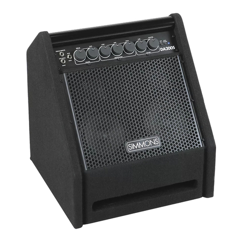
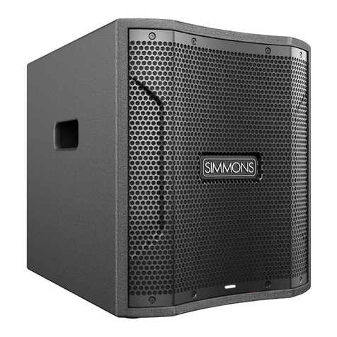
Simmons DA2100 Series User manual

SimmonsDrums.net
OWNER’S MANUAL
ADVANCED ELECTRONIC DRUM AMPLIFIERS
DA2100 SERIES
WILL USE K EYSHOT IMAGES HERE

4
Position your DA2100 Series amplifier in the desired location, and ensure the amp is stable.
INITIAL SETUP
Floor Pole
(speaker stand not included)
Free-standing
POWER
• Make sure the 1power switch is set to the OFF (0) position.
• Connect the included detachable IEC power cable from a power
outlet to the 2power cable input.
• The 3red voltage switch comes factory-set to the position
appropriate for the market where the amplifier is sold. For the USA,
this is 100-120V.
1
3
2

DA2100 SERIES ADVANCED ELECTRONIC DRUM AMPLIFIERS
5
• Each model in the DA2100 series ships with a removable mobile device holder as an accessory inside the retail packaging.
• When using your amp in floor wedge position, you can attach the holder to the front-panel as shown below.
• Slide the angled bottom end of the device holder into the 1front panel slot, until it 2clicks into place.
• Now you can keep your 3tablet or smart-phone held in a convenient position during performance or rehearsal.
• Please remove the cradle before transporting the amplifier, or when using the amplifier on a speaker pole or standing upright.
DEVICE HOLDER
BLUETOOTH®CONNECTING
BLUETOOTH®TROUBLESHOOTING
• Press the 1front panel On/Pair button so that the 2Bluetooth LED flashes, indicating that Bluetooth audio is enabled and ready for pairing
• From your Bluetooth source device, select your drum amplifier’s model number (DA2108, DA2110 or DA2112) to pair
• Play audio from your source device, making sure your device’s volume is turned up, as well as the amplifier’s volume
These steps should resolve any Bluetooth trouble you may encounter:
Power off the DA2100 Series amplifier and leave it off, then follow directions for Apple and Android devices below:
Then power on your DA2100 Series amplifier, press the Bluetooth On/Pair button, and follow the Bluetooth Connecting steps above
• On your Apple iOS device
1. Open Settings app, select Bluetooth
2. If your amplifier is listed under MY DEVICES, touch info button,
tap to Forget This Device
3. Turn off Bluetooth, wait 10 seconds, turn on Bluetooth
• On your Android device
1. Open Settings, select Bluetooth
2. If DA2012B is listed under Paired Devices, touch gear icon, and
tap to unpair
3. Turn off Bluetooth, wait 10 seconds, turn on Bluetooth
1
2
1 2 3

6
INPUTS
• Connect your electronic drum sound module’s audio outputs to the 1INPUT 1 jacks on the amplifier rear panel
• Stereo Input: use 2 cables to connect to both the INPUT 1 LEFT(MONO) and RIGHT jacks
• Mono Input: use 1 cable to connect to the INPUT 1 LEFT(MONO) input jack only
• If you’d like to amplify additional sources, connect them to the remaining rear panel inputs, or the front panel aux input
ROUTING SWITCH
• If you are using a single DA2100 series amplifier, set the 2rear panel switch to Mono
• For dual-amp stereo configuration, see Smart Stereo on the next page
DA2108 REAR PANEL
DA2110 REAR PANEL
DA2112 REAR PANEL
QUICK START: INPUT
1
2
2
2
1
1

DA2100 SERIES ADVANCED ELECTRONIC DRUM AMPLIFIERS
7
VOLUME CONTROLS
• Turn all 3input level control knobs to the minimum position
• DA2112 only: also turn the Master 4knob to minimum
VOICING SWITCH
• Set the 5Voicing switch to Floor when using the amplifier lying horizontally on the floor, or free-standing vertically
• Set the switch to Pole when using the amplifier on a speaker pole
POWER ON
• Power on the drum sound module and set its output volume to max
• Then power on the amplifier, via the rear panel switch
• DA2112 only: turn the Master 4knob to noon position
• Turn up the INPUT 1 knob 3while playing your drum sound module, until you reach a comfortable listening level
EQ
• Turn the EQ knobs 6to adjust your tone as desired
QUICK START: CONTROLS
DA2108 FRONT PANEL
DA2110 FRONT PANEL
DA2112 FRONT PANEL
3
46
6
6
3
3
5
5
5

8
A pair of DA2100 Series amplifiers can operate together as a Smart Stereo system, giving you control of the sound and volume of both amplifiers
from the first master amplifier, and optimally distributing all audio inputs to both for rich stereo sound.
• Use two like amplifiers: two DA2108s, two DA2110s, or two DA2112 amplifiers
• Set the switch on the first amplifier to Stereo Master
• Set the switch on the second amplifier to Link In
• Connect a standard microphone cable (female XLR to male XLR cable) from the first unit’s LINK OUT jack to the second unit’s LINK IN jack
CONNECT ALL INPUTS TO FIRST AMPLIFIER ONLY
• Connect all inputs and make all sound settings on the first (left) unit only, this will be the master amplifier
• All inputs and controls on the second amplifier will be disabled
• For headphones, use the headphone jack on the first amplifier
SMART STEREO WITH PAIR OF AMPLIFIERS
FIRST/MASTER/LEFT UNIT SECOND/LINKED/RIGHT UNIT

DA2100 SERIES ADVANCED ELECTRONIC DRUM AMPLIFIERS
9
SMART STEREO WITH SUBWOOFER OR DIRECT OUT
To connect a subwoofer, or a direct out, the setup is the same as on the opposite page, but you can add a connection from the first unit’s DIRECT
OUT jack to a subwoofer or other audio receiving device, as shown below.
• The DIRECT OUT provides a full-range, mono signal
• The DIRECT OUT level is not effected by the MASTER knob of the DA2112.
TO SUBWOOFER OR OTHER UNIT
FIRST/MASTER/LEFT UNIT SECOND/LINKED/RIGHT UNIT

10
1
1
1
2
2
2
3
3
3
4
4
4
5
5
5
6
6
7
7
7 8
12
12
12
13 14
11
11
11
9
9
9
18
15 16
16
16
17
17
17
10
10
10
CONNECTIONS AND CONTROLS
DA2108 REAR PANELDA2108 FRONT PANEL
DA2110 REAR PANELDA2110 FRONT PANEL
DA2112 REAR PANELDA2112 FRONT PANEL
REAR PANEL POWER
6 8
8

DA2100 SERIES ADVANCED ELECTRONIC DRUM AMPLIFIERS
11
1REAR PANEL BALANCED LINE INPUTS
Balanced or unbalanced line level sources can be connected here.
- Mono sources: connect to Left/Mono jack only
- Stereo sources: connect separate cables to Left/Mono and Right
2FRONT PANEL AUX INPUT
Use this input to connect the audio cable from a computer,
smartphone, tablet, or other audio source.
- This jack accepts stereo or mono input.
3BLUETOOTH AUDIO INPUT
The On/Pair button forces any currently connected Bluetooth
audio source to disconnect, and makes the amplifier available for
pairing.
The Off button disables Bluetooth.
To pair, look for your amplifier’s model number (DA2108, DA2110,
or DA2112) from your Bluetooth audio source device
- The LED blinks when available for pairing.
- The amplifier’s Bluetooth LED is lit solid when currently paired.
- The LED is off if Bluetooth has been disabled by a press of the
Bluetooth Off button.
When Bluetooth is off, and you press the On/Pair button
- The amplifier will automatically reconnect to the previous
Bluetooth audio source if it is available
- It will otherwise be available for Bluetooth pairing from a source
audio device such as a smartphone
4MONO / STEREO MASTER / LINK IN SWITCH
- Mono: This amplifier will output mono audio, and send mono
audio to the OUT jack so it’s available for any other amplifier or
sound system.
- Stereo Master: This amplifier will operate as the master unit of
a Smart Stereo pair. Use a mic cable (female XLR to male XLR
cable) to connect this amplifier’s LINK OUT to the LINK IN jack
of a second amplifier of the same type. All inputs should be
connected to the first master amplifier, which will also set the
volume and tone of both amplifiers.
- Link In: Use this setting for the second amplifier of a Smart
Stereo pair. The audio from the LINK IN will be routed directly
to the power amp and speaker, with all other inputs and
controls being ignored.
5FLOOR/POLE VOICING SWITCH
The switch tunes the amplifier to give a consistent frequency
response whether placed on the floor or on a speaker pole:
- FLOOR: standard tuning, to be used when the amplifier is lying
horizontally on the floor, or free-standing vertically on the floor
- POLE: optimizes the tuning for use on a speaker pole
6LEVEL KNOBS FOR REAR PANEL INPUTS
These knobs set the input volumes for the rear panel inputs.
7LEVEL KNOB FOR BLUETOOTH/AUX INPUT
This knob sets the input volumes for both Bluetooth audio input,
and the front panel aux input jack.
8EQ KNOBS
Adjust the overall sound of the amplifier for your sonic preference.
11 DIRECT OUT JACK
Sends out a mono mix of all input signals of the DA2108 or
DA2110.
- See
13 for DA2112’s direct out routing options.
10 LINK IN JACK
Activated only when 4switch is set to LINK IN
- Audio received at this jack is routed directly to the power amp,
bypassing the volume and EQ knobs of the receiving amplifier
- See previous page Smart Stereo configurations
11 LINK OUT JACK
Configured by 4switch
- Mono: sends out mono audio.
- Stereo Master: sends out right audio, for second amplifier’s
LINK IN.
- Link In: sends out the same audio received at the LINK IN jack.
12 STEREO HEADPHONE OUTPUT
Connect headphones here to hear a stereo mix of all input signals
of the DA2108 or DA2110.
- The headphone output level is determined by the input level
controls
DA2112 headphone output level is set by a dedicated 14 knob.
- See
13 for DA2112’s headphone routing options.
13 DA2112 ONLY: INPUT 3 ROUTING SWITCH
This feature can be helpful when you want to monitor a click track,
guide track or metronome, without it being amplified through the
speaker or sent to the direct out. Connect that source to INPUT 3,
and set this switch as desired:
- Center (normal): Input 3 goes to all outputs, like all other inputs.
- Left (Speaker+Phones): Input 3 goes to speakers and
headphones only, it is NOT included in the direct out.
- Right (Phones Only): Input 3 goes the headphones only, it is not
sent to speakers or direct out.
14 DA2112 ONLY: HEADPHONE LEVEL KNOB
Sets the level for headphones, independent of the DA2112 master
volume control
15 DA2112 ONLY: MASTER VOLUME KNOB
Adjusts the volume level from the amplifier and speakers,
independent of the headphone volume.
16 POWER LED
Lit when unit is powered on.
17 CLIP LED
Lit when power amp is clipping.
DA2108/DA2110: Turn down 6input level knobs if CLIP LED
lights.
DA2112: Turn down 6input level knobs or MASTER 15 knob if
CLIP LED lights.
18 POWER INLET, SWITCH, AND FUSE
Connect included power cable to power inlet.
- If amplifier will not power on and you suspect its fuse may
have blown, turn off the power switch, and open the fuse
compartment next to the power switch using a small flat blade
screwdriver.
- If metal strip in fuse is broken, replace with fuse type indicated on
rear panel.
CONNECTIONS AND CONTROLS

DA2100 SERIES ADVANCED ELECTRONIC DRUM AMPLIFIERS
13
Smart Stereo
A matching pair of DA2100 series amplifiers can be connected via a standard microphone cable, for unified
volume and tone control from the first master amplifier, with optimal distribution of mono and stereo audio
signals between both amplifiers, for immersive high-fidelity stereo sound
Floor/Pole Switch Configures amplifier for consistent frequency response whether used on the floor, or on a speaker pole
Rear Panel Inputs (1/2/3) Left/mono and right 1/4-inch TRS balanced/unbalanced compatible audio line inputs
Bluetooth Audio Input Bluetooth 5.0 Stereo Audio Input, with On/Pair and Off buttons plus LED
Front Panel Aux Input 1/8-inch mini TRS unbalanced input
Link In Jack XLR balanced +4dBv audio input
Link Out Jack XLR balanced +4dBv audio output
Direct Out Jack XLR balanced +4dBv audio output
Power LED Front panel white LED indicates power on
Clip LED Front panel red LED indicates power amp clipping
Power Cable Detachable IEC 3-connector USA standard
Power Input Switchable: 110-120V/60 Hz or 220-240V/50Hz
Cabinet Polypropylene
Grille 1.2mm steel
Speaker Pole Socket 35mm (1.35-inch) standard socket for speaker pole mounting (speaker pole not included)
Suspension Points DA2100 Series Units Are Not Designed For Suspension
DA2108 DA2110 D A 2112
Power Consumption 100W 400W
Power Output 100 Watts RMS
400 Watts Peak
350 Watts RMS
2000 Watts Peak
Headphone Output 3.5mm Stereo Jack
Silences speakers when connected
3.5mm Stereo Jack
Dedicated volume control knob
Input 3 Routing Not included To facilitate click track,
metronome and backing track
use in performance, input 3 can
be routed to
phones only,
phones and speakers only, or
phones, speakers and direct out
EQ Knobs Lows: -/+12dB @ 65Hz
Highs: -/+12dB @ 10KHz
Lows: +/-12dB @ 65Hz
Mids: -/+12dB @ 2.5KHz
Highs: -/+12dB @ 10KHz
Lows: +/-12dB @ 65Hz
Low Mids: -/+12dB @ 350Hz
High Mids: -/+12dB @ 2.5KHz
Highs: -/+12dB @ 10KHz
Volume/Level Knobs Input 1 Level knob
Bluetooth/Aux Level knob
Input 1 Level knob
Input 2 Level knob
Bluetooth/Aux Level knob
Input 1 Level knob
Input 2 Level knob
Input 3 Level knob
Bluetooth/Aux Level knob
Master Volume knob
Headphone Volume knob
Speaker Drivers 8-inch Low Frequency driver
1-inch Compression driver
10-inch Low Frequency driver
1-inch Compression driver
12-inch Low Frequency driver
1-inch Compression driver
Frequency Response 65-20K Hz 55Hz-20KHz 40Hz-20KHz
Max SPL@1M 118dB 120dB 126dB
Product Dimensions 17.25”W x 10.25”H x 10.1”D 20”W x 11.8”H x 11.45”D 24.1”W x 14.2”H x 14.2”D
Packaging Size 20.1”W x 13.4”H x 13.4”D 22.85”W x 15”H x 15”D 28.1”W x 18.1”D x 18.1”D
Net Weight 15.5 pounds 20 pounds 35 pounds
Gross Weight 19 pounds 24 pounds 45 pounds
SPECIFICATIONS

14
IMPORTANT SAFETY INSTRUCTIONS
Please keep this instruction manual for future reference and for the
duration of owning your Simmons DA2100 Series Advanced Electronic
Drum Amplifier. Please carefully read and understand the instructions
inside this owner’s manual before attempting to operate your new
amplifier.
This instruction manual includes essential safety information regarding
the use and maintenance of the amplifier. Take special care to heed all
warning symbols and signs inside this manual and those printed on the
amplifier panel on the back of the unit.
WARNING
TO PREVENT FIRE OR SHOCK HAZARD, DO NOT EXPOSE THE
AMPLIFIER TO WATER/MOISTURE, NOR SHOULD YOU OPERATE THE
AMPLIFIER NEAR ANY WATER SOURCE.
The exclamation point triangular symbol is intended to alert the user
to the presence of important operating and maintenance(servicing)
instructions in the user manual accompanying the Amplifier.
The lightning flash with an arrow triangular symbol is intended to alert
the user to the presence of non-insulated “dangerous voltage” within the
product’s enclosure, and may be of sufficient magnitude to constitute a
risk of electric shock.
WARNING
Handle the power supply cord with care.
Do not damage or deform it as it may cause electric shock or malfunction
when used. Hold the plug attachment when removing from wall outlet.
Do not pull on the power cord.
IMPORTANT SAFETY PRECAUTIONS
1. Read these instructions.
2. Keep these instructions.
3. Heed all warnings.
4. Follow all Instructions.
5. Do not use this apparatus near water.
6. Clean only with dry cloth.
7. Do not block any ventilation openings. Install in accordance with the
manufacturer’s instructions. DO NOT turn on the amplifier module
before connecting all other external devices.
8. Do not install near any heat sources such as radiators, heat registers,
stoves, or other apparatus (including amplifiers) that produce heat.
9. Do not defeat the safety purpose of the polarized or grounding-type
plug. A polarized plug has two blades with one wider than the other.
A grounding type plug has two blades and a third grounding prong.
The wide blade or the third prong is provided for your safety. If the
provided plug does not fit into your outlet, consult an electrician for
replacement of the obsolete outlet.
10. Protect the power cord from being walked on or pinched particularly
at plugs, convenience receptacles, and the point where they exit
from the apparatus.
11. Only use attachment/accessories specified by the manufacturer.
12. Use only the cart, stand, tripod, bracket or table specified
by the manufacturer, or sold with the apparatus. When
a cart is used, use caution when moving the cart/
apparatus combination to avoid injury from tip-over.
13. Unplug this apparatus during lightning storms or when unused for
long periods of time.
14. Refer all servicing to qualified service personnel. Servicing is required
when the apparatus has been damaged in any way, such as power-
supply cord or plug is damaged, liquid has been spilled or objects
have fallen into the apparatus, the apparatus has been exposed to
rain or moisture, does not operate normally, or has been dropped.
15. POWER SOURCES – This product should be operated only from the
type of power source indicated on the rating label. If you are not
sure of the type of power supply to your home, consult your product
dealer or local power company.
16. WALL OR CEILING MOUNTING – The product should never be
mounted to a wall or ceiling.
17. Where the mains plug or an appliance coupler is used as the disconnect
device, the disconnect device shall remain readily operable.
18. OBJECT AND LIQUID ENTRY – Care should be taken so that objects
do not fall and liquids are not spilled into the enclosure through
openings.
19. Water and Moisture: This product should be kept away from direct
contact with liquids. The apparatus shall not be exposed to dripping
or splashing and that no objects filled with liquids, such as vases, shall
be placed on the apparatus.
20. Keep the product out of extended or intense direct sun light.
21. No containers filled with any type of liquid should be placed on or
near the product.
22. SERVICING – The user should not attempt any service to the speaker
and/or amplifier beyond that described in the operating instructions.
All other servicing should be referred to qualified service personnel.
23. VENTILATION – Slots and openings in the amplifier are provided for
ventilation and to ensure reliable operation of the product and to
protect it from overheating. These openings must not be blocked
or covered. The openings should never be blocked by placing the
product on a bed, sofa, rug, or other similar surface. This product
should not be placed in a built-in installation such as a bookcase or
rack.
24. Protective earthing terminal: The apparatus should be
connected to a main socket outlet with a protective
earthing connection.
25. ACCESSORIES – Do not place this product on an unstable
cart, stand, tripod, bracket, or table. The product may fall, causing
serious injury to a child or adult, and serious damage to the product.
Use only with a cart, stand, tripod, bracket, or table recommended
by the manufacturer, or sold with the product.
26. When moving or not using the appliance, secure the power cord
(e.g., wrap it with a cable tie). Be careful not to damage the power
cord. Before using it again, make sure the power cord has not been
damaged. If the power cord has been damaged at all, bring the unit
and cord to a qualified service technician for repair or replacement as
specified by the manufacturer.
27. LIGHTNING – For added protection during a lightning storm, or when
it is left unattended and unused for long periods of time, unplug it
from the wall outlet. This will prevent damage to the product due to
lightning and power-line surges.
28. REPLACEMENT PARTS – When replacement parts are required, be
sure the service technician has used replacement parts specified by
the manufacturer or parts that have the same characteristics as the
original parts. Unauthorized substitutions may result in fire, electric
shock, or other hazards.
CAUTION: TO REDUCE THE RISK OF ELECTRIC
SHOCK DO NOT REMOVE COVER (OR BACK) NO
USER-SERVICEABLE PARTS INSIDE REFER
SERVICING TO QUALIFIED PERSONAL

DA2100 SERIES ADVANCED ELECTRONIC DRUM AMPLIFIERS
15
IMPORTANT SAFETY INSTRUCTIONS
To prevent electric shock, do not use a polarized plug with an extension
cord, receptacle or other outlet unless the blades can be fully inserted to
prevent blade exposure.
HEARING DAMAGE AND PROLONGED EXPOSURE TO
EXCESSIVE SPLs
Simmons Advanced Drum Amplifiers are capable of producing extremely
loud volume levels that can cause permanent hearing damage to
performers, production crews or the audience. Hearing protection is
recommended during long-term exposure to high SPLs (sound pressure
levels).
Remember, if it hurts, it is definitely too loud! Long term exposure to
high SPLs first causes temporary threshold shifts; limiting your ability to
hear the actual loudness and exercise good judgment. Repeated long
term exposure to high SPLs will cause permanent hearing loss.
Please note the recommended exposure limits in the accompanying table.
More information about these limits is available on the US government
Occupational Safety and Health (OSHA) website at: www.osha.gov.
WARNING: To reduce the risk of fire or shock do
not expose this equipment to rain or moisture.
AVERTISEEMENT: Pour réduire les risques
d’incendie et d’électrocution, ne pas exposer ce
matérial à la pluie ou à l’humidité.
RISK OF
ELECTRIC SHOCK
DO NOT OPEN
RISQUE DE CHOC
ELECTRIQUE NE
PAS OUVRIR
RISK OF
ELECTRIC SHOCK
DO NOT OPEN
RISQUE DE CHOC
ELECTRIQUE NE
PAS OUVRIR
CAUTION: To reduce the risk of electric shock, do not
remove chassis. No user-serviceable parts inside.
Refer servicing to qualified service personnel.
AVERTISEEMENT: Pour réduire les risques d’incendie et
d’électrocution, ne pas exposer ce matérial à la pluie ou
à l’humidité.
THIS SYMBOL IS INTENDED TO ALERT THE USER TO THE PRESENCE
OF IMPORTANT OPERATING AND MAINTENANCE (SERVICING)
INSTRUCTIONS IN THE LITERATURE ACCOMPANYING THE UNIT.
WARNING: To reduce the risk of fire or shock do
not expose this equipment to rain or moisture.
AVERTISEEMENT: Pour réduire les risques
d’incendie et d’électrocution, ne pas exposer ce
matérial à la pluie ou à l’humidité.
RISK OF
ELECTRIC SHOCK
DO NOT OPEN
RISQUE DE CHOC
ELECTRIQUE NE
PAS OUVRIR
RISK OF
ELECTRIC SHOCK
DO NOT OPEN
RISQUE DE CHOC
ELECTRIQUE NE
PAS OUVRIR
CAUTION: To reduce the risk of electric shock, do not
remove chassis. No user-serviceable parts inside.
Refer servicing to qualified service personnel.
AVERTISEEMENT: Pour réduire les risques d’incendie et
d’électrocution, ne pas exposer ce matérial à la pluie ou
à l’humidité.
APPARATUS SHALL NOT BE EXPOSED TO DRIPPING OR SPLASHING
AND THAT NO OBJECTS FILLED WITH LIQUIDS, SUCH AS VASES,
SHALL BE PLACED ON THE APPARATUS.
Permissible Noise Exposures (1)
Duration per day, hours Sound level dBA slow response
8 90
692
4 95
3 97
2 100
1.5 102
1 105
0.5 110
0.25 or less 115

16
CALL
TOLL FREE
888-621-4008
OR VISIT OUR WEBSITE AT: simmonsdrums.net
MISSING
damaged
parts?
assembly
questions?
WARRANTY
Two (2) Years limited warranty
Subject to the limitations set forth below, Simmons® hereby
represents and warrants that the components of this product
shall be free from defects in workmanship and materials,
including implied warranties of merchantability or fitness for a
particular purpose, subject to normal use and service, for three
(2) years to the original owner from the date of purchase.
Retailer and manufacturer shall not be liable for damages
based upon inconvenience, loss of use of product, loss of
time, interrupted operation or commercial loss or any other
incidental or consequential damages including but not limited
to lost profits, downtime, goodwill, damage to or replacement
of equipment and property, and any costs of recovering,
reprogramming, or reproducing any program or data stored
in equipment that is used with Simmons® products. This
guarantee gives you specific legal rights. You may have other
legal rights which vary from state to state. Some states do not
allow limitations on how long an implied warranty lasts, so the
above limitation may not apply to you.
Simmons
P.O. Box 5111 Thousand Oaks, CA 91359-5111
All trademarks and registered trademarks mentioned herein are
recognized as the property of their respective holders.
FCC STATEMENT
1. Caution: Changes or modifications to this unit not expressly
approved by the party responsible for compliance could void
the user’s authority to operate the equipment.
2. Note: This equipment has been tested and found to comply
with the limits for a Class B digital device, pursuant to part
15 of the FCC Rules. These limits are designed to provide
reasonable protection against harmful interference in a
residential installation. This equipment generates, uses and
can radiate radio frequency energy and, if not installed and
used in accordance with the instructions, may cause harmful
interference to radio communications. However, there is
no guarantee that interference will not occur in a particular
installation. If this equipment does cause harmful interference
to radio or television reception, which can be determined by
turning the equipment off and on, the user is encouraged
to try to correct the interference by one or more of the
following measures:
• Reorient or relocate the receiving antenna.
• Increase the separation between the equipment
and receiver.
• Connect the equipment into an outlet on a circuit different
from that to which the receiver is connected.
• Consult the dealer or an experienced radio/ TV technician
for help.
Warning: Changes or modifications to this unit not expressly
approved by the party responsible for compliance could void
the user’s authority to operate the equipment.
FCC Radiation Exposure Statement
The device has been evaluated to meet general RF exposure
requirements. The device can be used in a fixed/mobile (min
20cm) exposure condition without restriction.
1904-19376886
This manual suits for next models
3
Table of contents
Other Simmons Amplifier manuals

