Doc Ref: DG162
Issue Date: January 2017
Issue Number: 2
Simmonsigns Limited reserves the right to alter or improve this guide without prior notice.
simmonsigns.co.uk
+44 (0)7841 052 022
+44 (0)1952 293 333
Stafford Park 5
Telford Shropshire
TF3 3AS
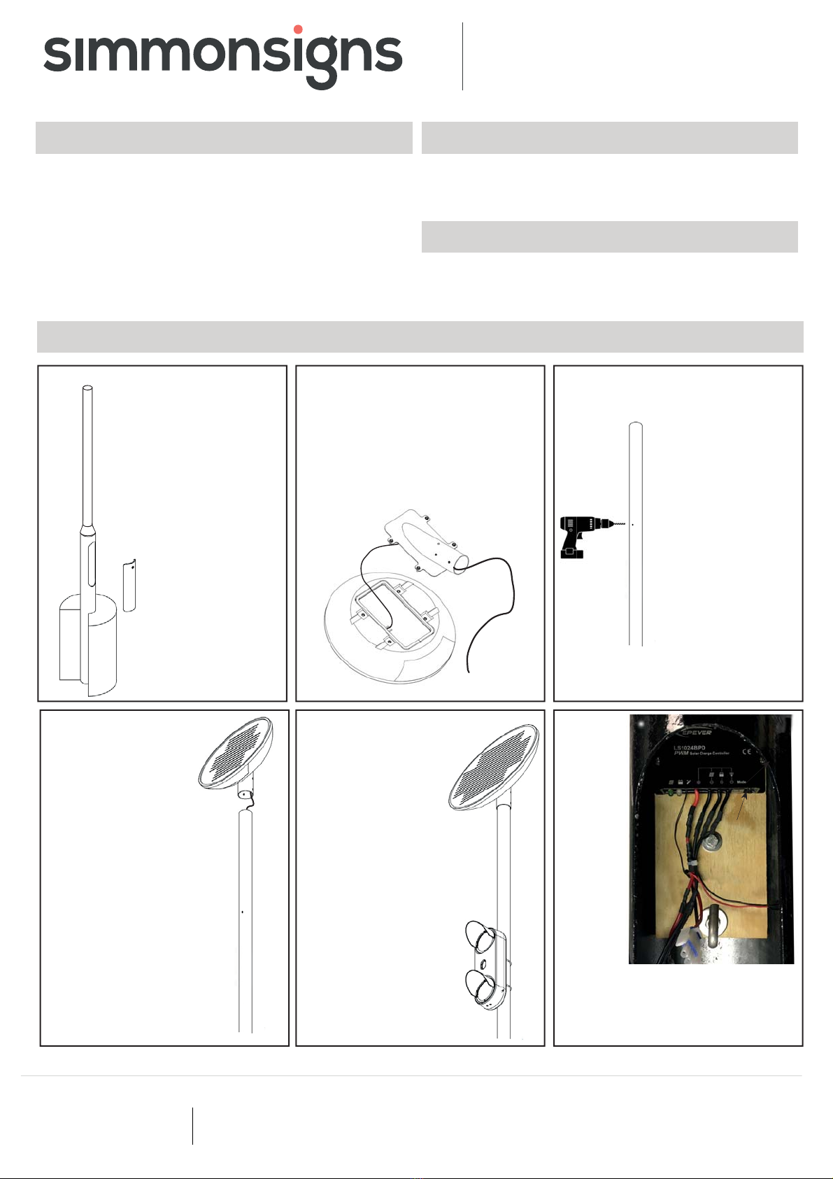
Installation Guide
Moving to
the column
base remove
the existing
wooden
board and
replace with
the regu-
lator board
assembly
supplied
In the following steps please ensure that the
connections are made in the following order :
1. Battery, 2. Load, 3. Solar panel.
Solar PULSA
SAFETY FIRST
INSTALLATION
Ensure that the site is surveyed for buried services and that
Ensure that the site is surveyed for buried services and that
any electrical supply is isolated before commencing work.
any electrical supply is isolated before commencing work.
All materials to be handled using suitable mechanical equip-
All materials to be handled using suitable mechanical equip-
ment or suffi cient manpower for the weight of the item being
ment or suffi cient manpower for the weight of the item being
handled.
TOOLS & MATERIALS REQUIRED
Tri-head Key.
5mm Allen key.
Electrical Screwdriver.
PACKING LIST
Box 1 - Solar panel
Box 2 - Solar PULSA
Box 3 - Solar Panel support,89mm U Bolt Kit, battery and regulator.
Side Cutters
13mm spanner
Ø14mm drill
The Solar PULSA
is supplied as a kit
designed to fi t onto a
pre-installed 89/168
column. The column
manufacturer should be
consulted to provide a
column and foundation
plan suitable for the
equipment to be mount-
ed and environmental
conditions peculiar to
the site.
Weights and dimensions
of the solar PULSA
equipment are shown
overleaf to help with
calculating the loads.
3Drill a Ø14mm
hole in the post
at the required
height (2421mm
from ground level
to give a height
of 2100mm to the
base of the Pulsa) -
Surface protect
the bare metal and
ensure the hole is
free from burrs and
sharp edges.
Assemble the solar panel support by
uncoiling the solar panel output lead
and feeding it through the panel support
bracket as shown.
Place the bracket over the aperture in
the panel back moulding and secure
with the 4 Tri-head screws supplied.
2
Solar panel
output lead
Panel back
moulding
Panel support
bracket
45
Doc Ref : IG197
Issue Date: January 2020
Issue Number : 2
Take the solar panel assembly
and feed the solar output lead
down the post from the top so
that it emerges in the column
base housing.
Place the solar panel assembly
on the top of the post and align
it to point directly South.
Ensure that nothing impedes the
solar panels view of the sun all
year round.
Tighten the grub screws to lock
the solar panels assembly onto
the post.
Fix the Pulsa to the post
in accordance with the
standard Pulsa installa-
tion instructions.
Pass the PULSA supply
cable down the post
via the drilled hole and
into the column base
housing.
1
6
On/Off Switch
Hook
Fixing screw


