SIMON URMET nea 14108 User manual
SIMON URMET
10154 Torino (Italy)
Via Bologna 152
Tel. +39 011 24 00 000
Fax. +39 011 24 00 249
www.simonurmet.com
Pulsante elettronico a sfioramento per
sistema domotico IPerHome
Electronic push-button for
IPerHome domotics system
DS14108-12-001BLBT9057
14108/12
12–24V
DC/AC, 50Hz
680
2
Descrizione
Il dispositivo è un comando elettronico per il controllo di carichi in ambiente
civile, provvisto di 1 sensore a sfioramento con segnalazione luminosa integrata
a mezzo di un led azzurro.
Funzionamento
• l'uscita verrà attivata tutte le volte che si premerà / sfiorerà (anche
brevemente) con un dito la zona limitrofa (superiore o inferiore) alla
segnalazione luminosa (led azzurro);
• l’intensità luminosa del led può essere regolata attraverso la programmazione
del sistema domotico IPerHome;
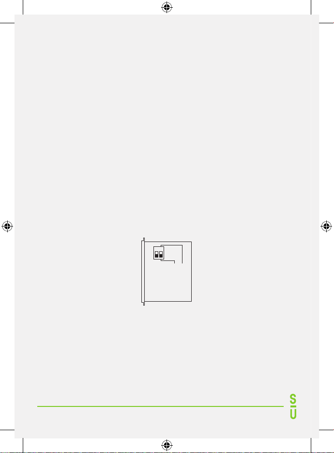
• è possibile regolare la sensibilità del dispositivo agendo sul dip-switch N2 a
lato del comando, come indicato nella Fig. 1.
- Dip-Switch ON = sensibilità alta
- Dip-Switch OFF = sensibilità bassa
ON
OFF
Sensibilità alta
Sensibilità bassa
N1 N2
Fig. 1
Pulizia placca
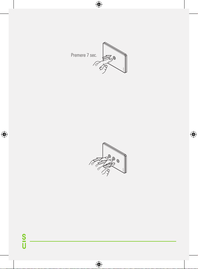
Per consentire una confortevole pulizia della placca in vetro è necessario
selezionare la modalità stand-by. Tale modalità si attiva mantenendo un dito
premuto sul dispositivo per almeno 7 secondi (vedi Fig. 2). L’attivazione della
modalità stand-by è confermata dal lampeggiamento della segnalazione luminosa
3
(led azzurro). La modalità di stand-by permane per 15 secondi. Il dispositivo ritorna
automaticamente al funzionamento normale allo scadere dei 15 secondi.
Premere 7 sec.
Fig. 2
Pulizia placca con più di un dispositivo elettronico installato
Qualora il punto di comando luce fosse composto da 2 o più dispositivi elettronici,
l’attivazione della modalità di stand-by deve essere attivata mantenendo
premuti simultaneamente tutti i dispositivi per almeno 7 secondi
(vedi Fig.
3)
. L’attivazione della modalità stand-by è confermata dal lampeggiamento
simultaneo di tutte le segnalazioni luminose (led azzurri). La modalità di
stand-by permane per 15 secondi. I dispositivi ritornano automaticamente al
funzionamento normale allo scadere dei 15 secondi.
Premere 7 sec.
Fig. 3
NOTA! Pulire la placca esclusivamente con un panno umido preventivamente imbevuto con una soluzione
d’acqua e sapone neutro. Non utilizzare prodotti chimici, abrasivi, solventi, ammoniaca o alcool per evitare di
danneggiare l’intero dispositivo.
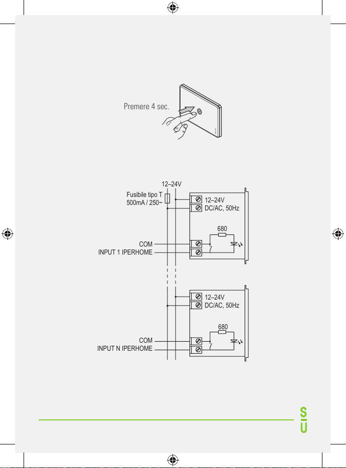
Funzione spegnimento Led (LED-OFF)
Per abilitare / disabilitare la funzione per lo spegnimento del led l’utente deve
premere e tenere premuto il sensore centrale e contare fino a 4 secondi, quindi
rilasciare il pulsante del sensore (vedi Fig. 4).
4
Per il riconoscimento della funzione il led lampeggia 3 volte e dopo 1 minuto
si spegne completamente. Il LED si riaccenderà solo dopo aver premuto un
pulsante.
Premere 4 sec.
Fig. 4
Collegamenti pulsante
12–24V
12–24V
DC/AC, 50Hz
COM
INPUT 1 IPERHOME
COM
INPUT N IPERHOME
Fusibile tipo T
500mA / 250~
680
12–24V
DC/AC, 50Hz
680

5
Note di installazione
Per la corretta installazione occorre attenersi alle seguenti regole:
• Non superare la potenza nominale del dispositivo;
• Non sottoporre il dispositivo ad esposizione diretta di fonti di calore;
•Associare il dispositivo alla relativa placca (14013.XX, 14023.XX, 14033.XX,
14044.XX);
•Utilizzare un fusibile ad alto potere di interruzione per proteggere il circuito
di alimentazione (ad es. cod. 10500.XX);
•Utilizzare gli appositi copriforo 14350 per chiudere i moduli lasciati vuoti
all’interno del supporto utilizzato.
•Si raccomanda di installare la placca prima di alimentare il dispositivo.
• Rispettare le polarità di collegamento.
Caratteristiche tecniche
Alimentazione: ..............................................................................12-24V AC-DC
Frequenza: ........................................................................................ 50Hz ± 10%
Potenza assorbita a riposo: ..............................................................17mW@12V
Potenza assorbita a riposo: ..............................................................34mW@24V
Assorbimento a riposo: ....................................................................1.4mA@12V
Assorbimento a riposo: ....................................................................1.4mA@24V
Area frontale sensibile: ...................................................... 1 sensore a 590 mm²
Conforme con: ....................................... EN 60669-1:1999 + A1:2002 + A2:2008
EN 60669-2-1:2004+A1:2009 + A12:2010
Conforme alle direttive comunitarie: ....................... 2014/35/EU (bassa tensione)
2014/30/EU (Compatibilità Elettromagnetica)
Corrente di uscita tipica: .....................................................................................2A
Temperatura ambiente di funzionamento: ................................................0 - 35°C
Umidità Max.: ..................................................................................................90%

6
Corretto smaltimento del prodotto
(Rifiuti elettrici ed elettronici)
Il marchio riportato sul prodotto e sulla documentazione indica che
il prodotto non deve essere smaltito con altri rifiuti domestici.
Per evitare eventuali danni all’ambiente o alla salute causati
dall’inopportuno smaltimento dei rifiuti, si invita l’utente a separare
il prodotto da altri tipi di rifiuti e di riciclarli in maniera responsabile per favorire
il riutilizzo sostenibile delle risorse materiali.
Gli utenti domestici sono invitati a contattare il rivenditore presso il quale e
stato acquistato il prodotto o l’ufficio locale preposto per tutte le informazioni
relative alla raccolta differenziata e al riciclaggio per questo tipo di materiali.

7
Description
The device is an electronic switch with built in touch sensor for load control. A
blue led indicator allows to locate the device in the dark.
Operation
• The output will be activated every time you lightly press / touch (even briefly)
with a finger the local area (upper or lower) to the visual indicator (blue
LED);
• The LED brightness can be adjusted by means of IPerHome domotics
system.
•
It is possible to set the device sensitivity by selecting dip-switch N2 (see
Pic. 1).
- Dip-Switch ON = maximum sensitivity
- Dip-Switch OFF = minimum sensitivity
ON
OFF
HI sensitive
LO sensitive
N1 N2
Pic. 1
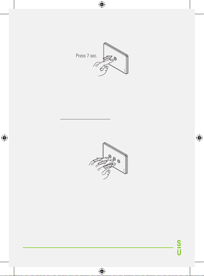
Cover plate cleaning
It is recommendable to enter the device into stand-by mode before cleaning the
glass cover plate. The state of inhibition is activated by firmly keeping a finger
on the device for at least 7 seconds (see Pic. 2).
Stand-by mode activation is confirmed by the blue led blinking. Device will stay
on stand-by mode for 15 seconds.
8
After the above time lapse the device automatically returns to normal
operation.
Press 7 sec.
Pic. 2
Cover plate cleaning with more electronic devices installed
If a cover plate includes 2 or more electronic devices the stand-by mode must
be activated by pressing simultaneously all devices for at least 5 seconds
(see Pic. 3). Stand-by mode activation is confirmed by all the relevant blue led
blinking. Devices will stay on stand-by mode for 15 seconds. After the above
time lapse devices automatically return to normal operation.
Press 7 sec.
Pic. 3
WARNING! Clean with a water wet cloth only. Do not use any chemical, abrasive product, solvent,
ammonia or alcohol.
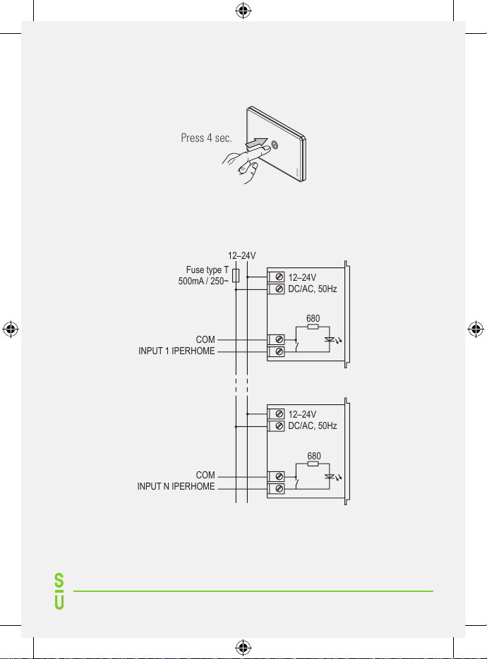
Led-off function
To enable/disable the led-off function the user has to press&hold the sensor
(both sensors for dimmer and shutter) and count to 4 second then release the
sensor button. (Pic. 4)
9
For acknowledgement, the led flashes 3 times, and after 1 minute will turn off
completely .The LED will relight up only after pressing a contact.
Press 4 sec.
Pic. 4
Installation Diagrams
12–24V
12–24V
DC/AC, 50Hz
COM
INPUT 1 IPERHOME
COM
INPUT N IPERHOME
Fuse type T
500mA / 250~
680
12–24V
DC/AC, 50Hz
680

10
Installation hints
For a proper installation simply comply with the following hints:
• Do not exceed the rated current of the device;
• Do not expose the device to external heat;
•
Match the device with a proper glass cover plate (14013.XX, 14023.X, 14033.XX,
14044.XX);
• Use a high breaking capacity fuse to protect the circuitry against overload or
short-circuit (cod. 10500.XX);
• Use the appropriate blank covers (part number 14350) to complete empty
spaces on mounting brackets.
• It is recommended to install the cover plates before power on.
• Do not reverse the connection polarity.
Data Specifications
Mains supply: ................................................................................12-24V AC-DC
Frequency: .........................................................................................50Hz ± 10%
Standby consumption: ......................................................................17mW@12V
Standby consumption: ......................................................................34mW@24V
Standby current: ...............................................................................1.4mA@12V
Standby current: ...............................................................................1.4mA@24V
Sensor Area: ........................................................................1 sensor of 590 mm²
Standard: ....................................... EN 60669-1:1999 + A1:2002 + A2:2008
EN 60669-2-1:2004+A1:2009 + A12:2010
In compliance with Community directives: 2014/35/EU (Low voltage)
2014/30/EU (Electromagnetic compatibility
Maximum Load current ....................................................................................2A
Operating temperature: ...........................................................................0 - 35°C
Relative humidity: .........................................................................................90%
11
Correct disposal of this product
(Waste Electrical & Electronic Equipment)
This marking on the product, accessories or literature indicates
that the product should not be disposed of with other household
waste.
To prevent possible harm to the environment or human health from
uncontrolled waste disposal, please separate these items from other types
of waste and recycle them responsibly to promote the sustainable reuse of
material resources.
Household users should contact either the retailer where they purchased this
product, or their local government office, for details of where and how they can
take these items for environmentally safe recycling.
This product is RoHS compliant.

12
Table of contents
Languages:


