SIMONINI Racing MINI 3 User manual

page 1
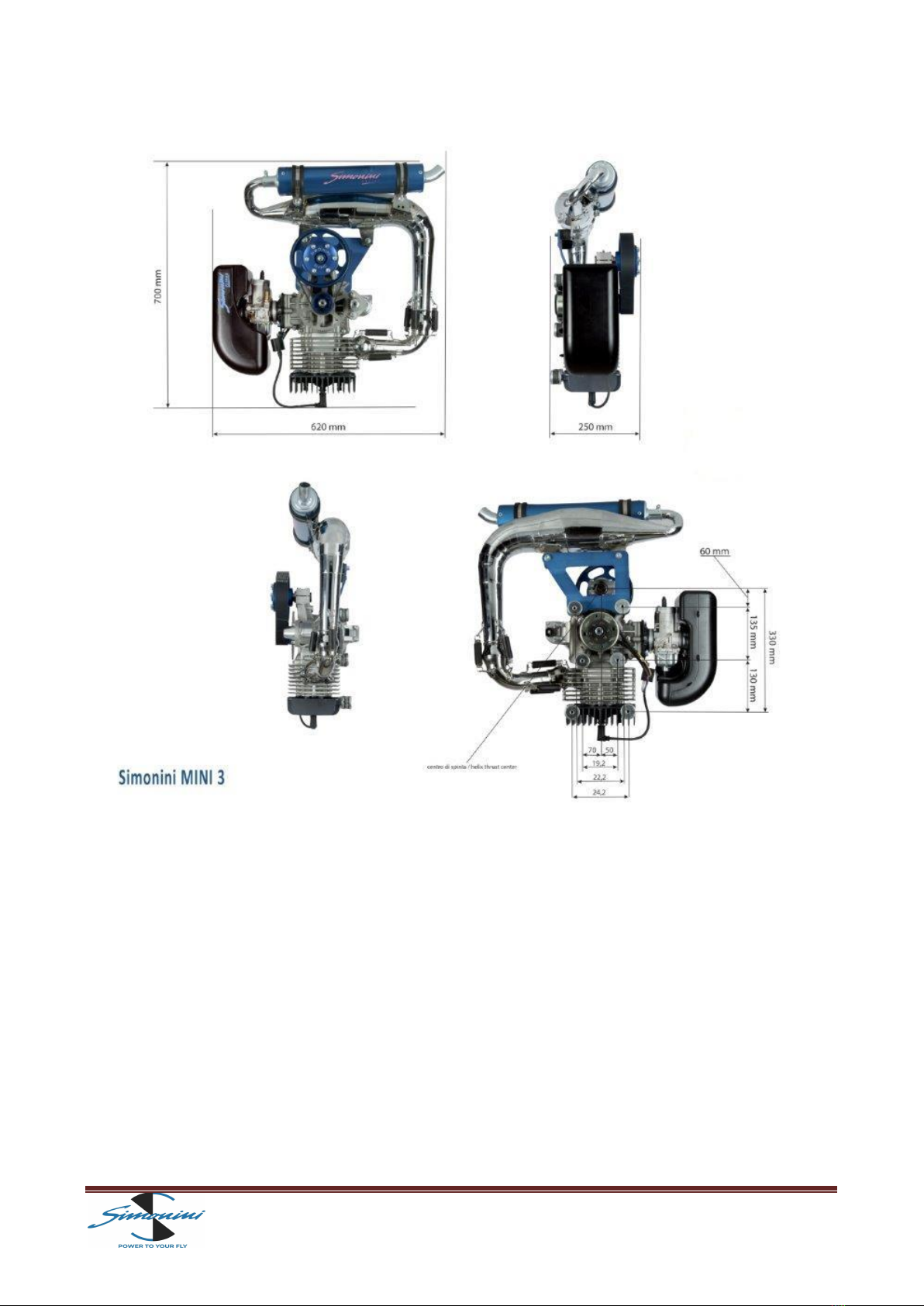
MINI 3
This handbook aims to bring to the attention of key technical, functional and maintenance of your motor MINI 3. Read carefully the following pages, will be synonymous
with safety, reliability and great satisfaction durable.
This manual is considered part of the motor MINI 3, in case of transfer, will be delivered to the new owner.
About this manual lists all of the information available at time of printing. The SIMONINI RACING srl reserves the right to modify or change without notice.

page 2
TECHNICAL DATA
BORE 72,8mm
STROKE 65mm
DISPLACEMENT 270cc
COMPRESSION RATIO 10.1 / 1
Weight ready to fly 22 kg
CONSUMPTION A 5400 rpm 3,2litres/hour
POWER 7000 rpm 36hp
STATIC THRUST Over 100Kg
Lamellar intake with Bing 36mm carburetor
Aluminum cylinder with ceramic coating magnesium,
Exhaust resonance
Poly-V belt reduction
Electronic ignition
Electric start
Alternator battery charger in flight
Airbox
Lubrication premix: 2.5% with premium-grade gasoline
3.0% with unleaded fuel
REDUCTION RATIOS AVAILABLE:
1:249 crown 159 mm / Pinion 64 mm
1:258 crown 159 mm / Pinion 62 mm
1:276 crown 159 mm / Pinion 58 mm
page 3

page 4
MINI 3/01
KIT ENGINE SCREWS
MINI 3/29
WASHER-PRESSURE OUTLET
MINI 3/64
COMPLETE SET OF BEARINGS
MINI 3/02
COMPLETE EXHAUST SYSTEM
MINI 3/31A
REED VALVE NEW MODEL
MINI 3/65
COMPLETE ROD
MINI 3/03
COMPLETE SET OF GASKETS
MINI 3/33
AIR FILTER
MINI 3/66
ROD CAGE
MINI 3/04
COMPLETE SET OF ENGINE SCREWS
MINI 3/35
BING 54 CARBURETTOR
MINI 3/69
COMPLETE PISTON AND RINGS
MINI 3/05
CYLINDER HEAD GASKET
MINI 3/39A
RUBBER MANIFOLD NEW MODEL
MINI 3/69A
TWO RINGS MM. 72,80
MINI 3/06
KIT SCREWS FOR HEAD ( 4 )
MINI 3/41
CRANK-CASE
MINI 3/70
RECTIFIER RECHARGE BATTERY
MINI 3/07
CYLINDER HEAD
MINI 3/46
ECCENTRIC PINION
MINI 3/71
SPARK PLUG BR 10 ES
MINI 3/08
KIT SILENT-BLOCK (6)
MINI 3/47
SEEGER REDUCTION
MINI 3/72
PLATE FOR FIXING EXHAUST
MINI 3/09
KIT SCREWS FOR CYLINDER
MINI 3/48
SET OF REDUCTION BEARINGS
MINI 3/73
EXHAUST MANIFOLD AND
SPRINGS
MINI 3/10
CYLINDER
MINI 3/52
POLY-V BELT
MINI 3/74
EXHAUST GASKET
MINI 3/11
CYLINDER GASKET
MINI 3/53
REDUCTION PULLEY
MINI 3/75
RUBBER FOR SPARK PLUG
MINI 3/16
STATOR
MINI 3/54
ALUMINIUM PLATE FOR PROP
MINI 3/76
NUT AND WASHER FOR FLYWHEEL
MINI 3/17
FLY WHEEL
MINI 3/58
REDUCTION PINION
A72
COMPLETE AIRBOX
MINI 3/19
SCREW AND WASHER FOR PINION
MINI 3/59
CROWN WHEEL
A73
SPONGE FOR AIRBOX
MINI 3/23
ALUMINIUM PLATE FOR COIL
MINI 3/61
COMPLETE ELECTRIC STARTER
A74
RUBBER FOR AIRBOX
MINI 3/25
COMPLETE COIL
MINI 3/62
COMPLETE CRANKSHAFT AND ROD
A75
CLAMP FOR AIRBOX
MINI 3/28
ALUMINIUM PLATE FOR STATOR
MINI 3/63
COMPLETE SET OF SEALS
page 5
TIGHTENING TORQUES
Description
Special number in table
NM
Kgf.m
Head Nut
6x40 Screws
Connector
6x30 Screws
6x25 Screws
Nut 12
12x30 Screws
8x40 Screws
Spark Plug
6
44
29
37
44
19/76
51
42
71
22
12
10
12
10
54
60
24
18
2.2
1.2
1.0
1.2
1.0
5.4
6.0
2.4
1.8
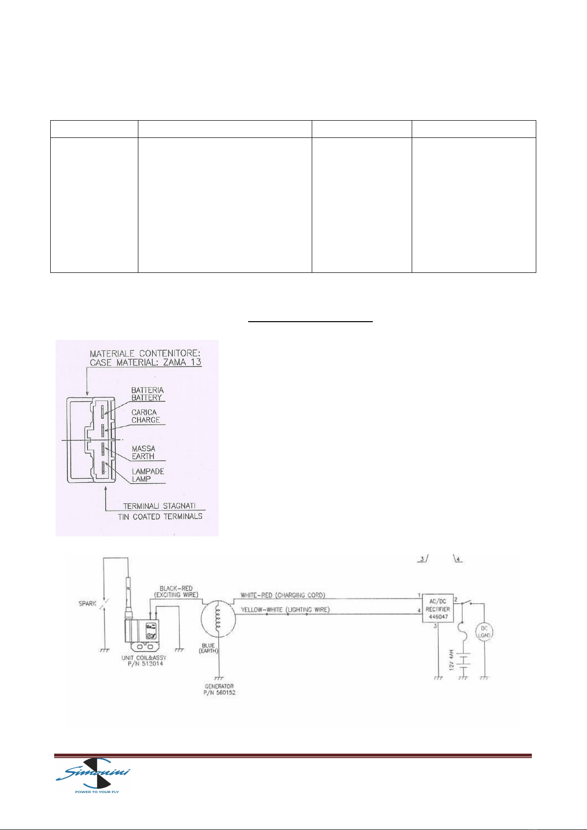
ELECTRICAL DIAGRAM

page 6
INSTALLATION
The MINI 3 engine must be fitted to the frame using its six elastic supports "silent
blocks", radially mounted: two placed on the head and four on the back of the
engine.
During the installation, some safety precautions must be made: remember that an
engine generates vibrations, even if very few, which can cause the loosening and/or
removal of screws or any other object. Therefore, to prevent any engine
components may cause damage to persons and/or property, make sure the engine
through a small steel cable. Components normally "made safe" are:
• The filter and the carburetor to the engine
• The springs and exhaust to the engine
• The engine itself to the frame, bypassing the silent blocks. In this case we will
use the "webbing" of synthetic fiber is particularly resistant to traction and tearing.
•The silent blocks and the silencer.
The mouth of the spherical muffler should be lubricated with grease resistant to
high temperatures (e.g. copper grease) before being implanted in the exhaust
manifold.
We recommend taking maximum care when carrying out these operations: in any
case, during the assembly phase the proper choices must be made by expert and
qualified personnel.
FUEL
The MINI 3 engine is designed to operate with a gasoline/oil mixture.
We recommend using oil-based semi-synthetic (for example, BARDAHL with API TC
specification) that, although inferior to a pure synthetic, remains mixed with
gasoline in the tank for a longer period. It grants good lubrication and longer life to
engine components.
During the running-in stage, use an oil percentage of 3.5% and then move to 3%
once the stage has been completed.
The gasoline must have an octane number that is not lower than 95, in order to
avoid pre-ignition phenomena.
Carefully mix the fuel oil in a tank is appropriate and it is better, once mixed, to use
it within a week. Do not use vegetable or animal oil. DO NOT MIX DIFFERENT TYPES
OF OIL. We do never recommend using Castrol TTS Oil. No guarantees by using this
oil will be applied.

page 7
CARBURETOR and FUEL PUMP
The carburetor BING 54/36, if used properly, provides good performances requiring
few tuning intervention. However, changes in weather conditions, altitude and a
possible change of the propeller (both in size and pitch) can affect its functioning.
The carburetor is adjusted during the testing phase with a standard setting. To
adjust the carburetor on the basis of these different situations, smaller or larger jets
are available.
The MINI 3 is equipped with a depression pump that draws fuel directly from the
tank. The draft tube has to no longer than 80 cm.
CARBURATION
Warning: in this paragraph the words "MIXTURE" indicates the union of the two elements (AIR) + (OIL /GASOLINE)
which takes place inside the carburetor
Weather conditions or altitude changes have influence to the operation of the
engine as it varies the air density and, consequently, changes the mix ratio between
the element AIR and the element OIL /GASOLINE.
In general, we can say that at high altitude, high humidity or high temperatures, less
air enters and therefore the mixture is richer in oil/gasoline: you will have to re-
establish the proper relationship by replacing the main jet with a lower measure.
In contrast, with low temperatures and low humidity, the air will become denser
than the lean-burn oil / gasoline, and consequently you will have to install a bigger
main jet.
WARNING: A mixture that is too low in oil/gasoline causes considerable damage to
the engine, which can cause it to break down and/or stop suddenly. It is
recommended to carry out the carburetion operations with the ENGINE SWITCHED
OFF!

page 8
RUNNING-IN
WARNING
• Before starting the engine, make sure that there are no loosened screws or
improperly attached parts;
• Ensure that any persons are at a distance of absolute safety and never in range of
the propeller;
•Do not start the engine where there are rocks or other objects that the force
generated by the propeller can lift and throw even at a considerable distance;
• Do not start the engine without propeller and without exhaust;
• Do not start the engine indoors: the exhaust gases contain poisonous carbon
monoxide which is toxic and can cause loss of consciousness and death.
The engine, before being sold, was subjected to a pre-running-in to verify the proper
operation and a test that confirms all the features advertised.
Once you require a MINI 3, you should pay particular attention to the first hour of
operation, in order to ensure all the engine’s qualities over time.
DURING THE RUNNING-IN PHASE, KEEP PARTICULAR ATTENTION TO THE EXHAUST GAS
TEMPERATURE AND HEAD TEMPERATURE UNDER CONTINUOUS OBSERVATION.
After having selected a suitable place and above all free from gravel or other
materials that may damage the moving parts, start the engine and let it warm up for
10 minutes at 2500 rpm, then slowly bring the engine to an higher system ,
decreasing and increasing the speed at intervals of 1 minute, thus going to affect
various "range" of use, but without exceeding the 4500 rpm. Absolutely avoid the
constant and repeated closing/opening the gas valve. After about 20 minutes from
start-up, shut down the engine and let cool completely.
WARNING! When the engine is running and even after its shutdown, it can cause
burns: so make sure it is completely cooled before working on it.
Proceed with a thorough visual inspection of any anomalies or loose parts. Once you
make sure everything is working properly and there are no problems of any kind,
you must repeat the previous operation for another 20 minutes of running,
respecting the same indications.
Last running-in phase: warm up the engine again for 10 minutes at 2500 rpm and
then, as in the two previous operations, gradually increasing the RPM. Now you can
wander over the entire range of use of the engine, bringing it several times to the
maximum speed at intervals of 1 minute.
After 20 minutes you can turn off the engine and, once cooled, you will proceed to a

page 9
full-tightening the screws on the MINI 3. Now the engine MINI 3 will be ready for
use for which it was designed by continuing to use a percentage of oil by 3% for the
next 10 hours.
WARNING! DURING THE RUNNING-IN PHASE, KEEP PARTICULAR ATTENTION TO THE EXHAUST GAS
TEMPERATURE AND HEAD TEMPERATURE UNDER CONTINUOUS OBSERVATION.
MAINTENANCE
Each time you use the engine, remember to perform routine checks pre-start-up:
• Check the silent block condition in complete integrity
• Make sure the exhaust does not present any cracks
• Ensure that the propeller does not present cracks or dents
• Make sure you have enough fuel, according to the duration of intended use of the
engine.
• Check that the electrical system and cables do not show abrasions or disruption.
• Check that there are no screws or parts loosened.
BELT TENSION
WARNING: CARRY OUT THE OPERATIONS WITH THE ENGINE SWITCHED OFF AND COOLED DOWN
During operation, the belt is under strain and wear and as result, lengthening
occurs, which could lead to sliding on the pulleys, with a subsequent decrease in
the general engine performance.
To restore the proper tension, loosen the screw M8 (No. 42) on the foot of the
engine which fastens the pulley can, turn screw M12 (n°51) anti-clock wise using
force of 1.8 Kgm and then re-tighten screw M8 (n°42)
INTERVENTIONS EVERY 20 HOURS
• Clean filter carburetor
• Clean fuel filter
• Check the belt tension and condition
• Lubricate the ball joint of the muffler
INTERVENTIONS EVERY 60 HOURS
• Replace the engine and exhaust silent blocks
page 10
• Replace the transmission belt
• Check the status of the intake manifold rubber
• Replace the exhaust pipe sound-absorbent material
• Check the electrode gap spark-plug: if it is over 0.6 mm, change the spark plug
• Rubber components such as belt transmission, silent block, intake manifold and
depression tube may be damaged by atmospheric agents. Their durability can
therefore be different from what is reported, you should therefore check their
condition and provide a possible replacement even outside the agreed time.
INTERVENTIONS EVERY 200 HOURS
• Replace all the bearings (N°64 + N°48)
• Replace all oil seals (N°63)
• Check the internal parts of the engine and carry out their replacement in case
the height limit confirm it is necessary.
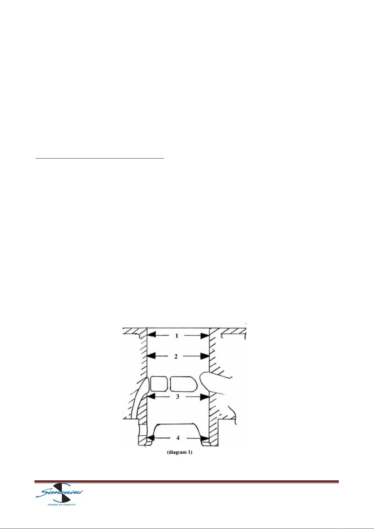
• Cylinder:
-must not show signs of seizure or scratches on the filling material (nickel
silicon);
-check the wear of the cylinder in the four points (shown in diagram 1) on X
and Y axles, none of the heights obtained must exceed the height limits:
SELECTION A: 72.830mm
SELECTION B: 72.840mm
SELECTION C: 72.850mm
SELECTION D: 72.860mm
The selection is shown with a letter at the bottom of the cylinder
• piston:

page 11
-There must not be any signs of seizure or deep cracks.
-Check the wear by measuring the piston at 18.5mm from the bottom keeping
the measuring instrument at a right angles to the axis pin.
Height limits:
SELECTION A: 72.690mm
SELECTION B: 72.700mm
SELECTION C: 72.710mm
SELECTION D: 72.720mm
• The pin must not be blue because that indicates a high working temperature and
the external diameter must not be less than 17.990mm.
• Measure the slack between the piston ring and its seat: slack height limit 0.1mm.
• Piston ring: insert a piston ring in the cylinder one by one, by using the piston, so
it is a square, measure the gap that is created between the two ends of piston ring
using feeler gauge. Height limit: 0.7mm
• Crankshaft: supporting the crankshaft at the two working points of oil seals, with
two comparators, measure the centering at the two working points of the bearings,
marked on diagram 2 with the letter A. Height limit: 0.05mm
• Measure the bearing seating, which must not be lower than the height limit:
24.98mm
•Check with a feeler gauge that the axle slack of the connecting-rod between the
two semi shaft, which must not exceed the height limit: 0.7mm
• Check the radial slack of the connecting rod on the coupling axle which must not
exceed the height limit: 0.05mm. This is detected by placing a comparator (B), as
page 12
shown in diagram 2, and moving the connecting rod vertically. The slack shown by
the comparator is assessed. Measure the diameter of the hole in the connecting-rod
foot. Height limit: 20.00mm
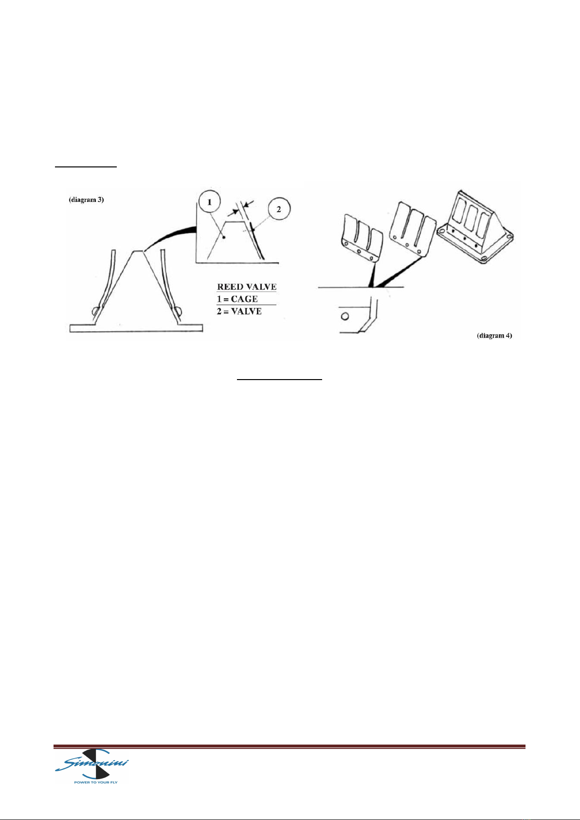
• Reed valve: Verify that between the frame and the reeds there is no space
(diagram 3). Height limit: 0.2mm.
WARNING: The reeds should not and cannot be turned (diagram 4)
TEMPERATURE
The MINI 3has been designed to work under certain operating temperatures: so
please stick strictly as written.
Temperatures that must not be exceeded when cruising or when the engine is at a
fixed rpm for a long time:
• Exhaust gas temperature 580 ° C.
• Temperature under spark plug 170 ° C.
Temperatures that must not be exceeded when taking off or when all the power is
required to the engine:
• Exhaust gas temperature 673 ° C.
•Temperature under spark plug 240 ° C.
WARNING engine will NEVER, at any time and condition, exceed:
• 670 ° C temperature of the exhaust gas.
• 240 ° C temperature under spark plug
It therefore makes it appropriate to adopt an instrument that detects these
temperatures for the protection of the engine, but especially for your and others'
safety.

page 13
We also inform you that high exhaust gas temperatures, in many cases, are a
symptom of poor carburetion. While high temperatures under the spark plugs,
usually, are due to poor ventilation (heat dissipation) of the engine, caused by the
presence of bodies and / or materials that prevent the passage of air cooling.
COMPONENTS AND TOOLS ON REQUEST
To have the possibility to customize the engine and then adapt it to different needs
and methods of use, SIMONINI offers a range of components on request:
▪PINION
In three different diameters (58/62/64) as well as providing the proper
reduction ratio, can be used to soften or make more rapid rise in engine
speed or to move, maintaining the propeller revolutions, any points of the
torque curve that does not meet your needs at a specified "range" of use, as
when cruising.
Code MINI3/53 mm. 58
Code MINI3/53 mm. 62
Code MINI3/53 mm. 64
▪PROPELLERS
We propose a two-blades wooden propeller, tractor or pushing configuration
Code E03 cm. 145
▪MAINTENANCE TOOLS
To facilitate maintenance operations, we propose two distinct tools with the
aim of extracting the ignitions flywheel and engine pulley:
Code U01 Pinion extractor
Code U02 Fly-wheel extractor

page 14
REQUEST FOR REPAIR OR REPLACEMENT OF WARRANTED
ATTENTION
The warranty is valid for 12 months from date of purchase and it covers all the
engine parts. It does not include the parts subject to wear: cylinder Nikasil, piston
and drive belts. There is NO warranty if the engine is tampered or if any not original
parts has been fitted without our approval.
In the case you need, please send the engine to
SIMONINI RACING srl
indicating:
• name
• address
• number the engine
• date of first start
• hours of operation
• any previous repairs
• carburetion setting
• complete description of the problem
Thank you for your trust and we remind you that the staff of SIMONINI RACING srl will be at your
disposal for any questions.
SIMONINI RACING SRL
Via per Marano 4303, Loc. San Dalmazio - 41028 Serramazzoni (Mo)
Tel 0536/953005 Fax 0536/953006.
Http: www.Simonini-flying.com E-mail: [email protected]
Table of contents
Other SIMONINI Racing Engine manuals

Popular Engine manuals by other brands


Desert Aircraft
Desert Aircraft DA170 owner's manual

GEIGER
GEIGER GB45MR Series Original assembly and operating instructions
 instructions")
THUNDER TIGER
THUNDER TIGER PRO-39H(R) instructions

Briggs & Stratton
Briggs & Stratton PROFESSIONAL SERIES 110000 Operator's manual

woodmizer
woodmizer LT28 G19 Safety, Operation, Maintenance & Parts Manual

Detroit Diesel
Detroit Diesel MBE4000 Service manual