Simphonics SMx User manual

Copyright © 2014 SimPhonics, Incorporated, All Rights Reserved
SMx Audio System
User’s Manual

SMx Audio System User's Manual, V1.41
SimPhonics, Inc.
Page 2 of 77
Page 2 of 77
Copyright © 2014 SimPhonics, Incorporated, All Rights Reserved
Contents
1Preface ...............................................................................8
1.1 Trademarks and Copyrights .....................................................................8
1.2 Before Reading this Document .................................................................8
1.3 Revision History .....................................................................................9
1.4 Terms and Acronyms ............................................................................11
1.5 References .......................................................................................... 11
2Introducing SMx ................................................................. 12
2.1 What is an SMx System? ....................................................................... 13
2.2 Complete Audio and I/O System Solution ................................................ 13
2.3 SMx Terminology ................................................................................. 13
3System Architecture ............................................................ 13
3.1 Overall System Block Diagram ............................................................... 15
3.2 SMx Audio System ...............................................................................16
3.3 SMx Super Mixer .................................................................................. 17
3.4 Individual Mixers..................................................................................18
3.5 Individual Mixer Module ........................................................................ 19
4Hardware .......................................................................... 20
4.1 Specifications ...................................................................................... 20
4.2 Electrical Characteristics ....................................................................... 21
4.3 Audio Performance ............................................................................... 21
4.4 Transport Delay ................................................................................... 21
4.5 Reliability and Maintainability ................................................................ 21
4.6 CPU Chassis ........................................................................................ 22
4.7 Motherboard and Processor....................................................................23
4.8 Diskless Operation................................................................................ 23
4.9 SMX Breakout box ................................................................................24
4.10 Cable Limitations ................................................................................. 24
4.11 Recommended Mating Connectors .......................................................... 25
4.12 SMX PCI DSP Card................................................................................ 26
4.13 Simulated Hardware ............................................................................. 27
4.14 Sound Cards........................................................................................ 27
4.14.1 Setting the Sample Rate Conversion Quality ............................................ 27
4.14.2 Controlling the Sound Cards .................................................................. 28
4.15 Power-up and down Sequence ............................................................... 29
4.15.1 Powering Up the System ....................................................................... 29
4.15.2 Powering Down the System ................................................................... 29
5SMx System Interconnect ..................................................... 29
5.1 SMx Breakout Box DIP Switch Settings ...................................................30
5.1.1 Master/Slave DIP Switch ....................................................................... 30
5.1.2 Phantom Power Switches....................................................................... 31
5.2 Connecting SMx Cards to SMx Master Boxes ............................................ 32
5.3 8 Channel System ................................................................................ 33
5.4 16 Channel System ..............................................................................34
5.5 24 Channel System ..............................................................................35
5.6 32 Channel System ..............................................................................36
5.7 40 Channel System ..............................................................................37

SMx Audio System User's Manual, V1.41
SimPhonics, Inc.
Page 3 of 77
Page 3 of 77
Copyright © 2014 SimPhonics, Incorporated, All Rights Reserved
5.8 48 Channel System ..............................................................................38
5.9 56 Channel System ..............................................................................39
5.10 64 Channel System ..............................................................................40
6Software Installation ........................................................... 41
6.1 Minimum Software Requirements ........................................................... 41
6.2 Installing V+ ....................................................................................... 41
6.3 Installing the SMx Audio System Software...............................................42
6.4 Updating the SMx Audio System Software ...............................................43
6.5 Configuring SMx within V+ ....................................................................44
7Registry Settings ................................................................ 46
7.1 Changing Registry Settings.................................................................... 47
8Using V+ with SMx .............................................................. 48
8.1 Application Examples............................................................................ 48
8.2 The SMx Super Mixer ............................................................................ 49
8.3 SMx I/O Devices for the SMx Audio System .............................................49
8.3.1 SMx Analog In Gain Boost Device ........................................................... 50
8.3.2 SMx Analog In Meters Device................................................................. 51
8.3.3 SMx Analog In to Analog Out Mixer Device .............................................. 52
8.3.4 SMx Analog Out Master Volume Device ................................................... 53
8.3.5 SMx Analog Out Meters Device............................................................... 55
8.3.6 SMx Wave In Mixer Device .................................................................... 56
8.3.7 SMx Wave Out Meters Device................................................................. 57
8.3.8 SMx Wave out Mixer Device................................................................... 58
8.3.9 SMx Wave Out to Wave in Mixer Device .................................................. 59
8.3.10 SMx Status Device ............................................................................... 60
8.3.11 Simulated Hardware Mode..................................................................... 60
8.4 “2103 SMx W I/O Select to A I/O” Object ................................................63
8.4.1 “2103 SMx W I/O Select to A I/O” .......................................................... 63
8.5 “2023 SMx Local ICS” Object ................................................................. 64
8.5.1 Local ICS Only ..................................................................................... 64
8.5.2 Networked ICS versus Local ICS............................................................. 64
8.5.3 Object 2023 ........................................................................................ 64
8.5.4 STATIC DATA....................................................................................... 65
8.5.5 SIDETONE ........................................................................................... 65
8.5.6 BE CAREFUL WHEN SETTING UP THE AI AND AO CHANNELS ...................... 66
8.5.7 DO NOT USE MORE THAN ONE ICS WITH THE SAME PARAMETERS ............. 66
8.5.8 SAMPLE WORKSHEET............................................................................ 66
8.5.9 PRACTICAL APPLICATION ......................................................................67
8.6 Super Mixer V+ Examples .................................................................... 68
8.6.1 Controlling the Super Mixer’s Master Gains ..............................................68
8.6.2 Monitoring the Super Mixer’s Meters ....................................................... 69
8.6.3 Controlling the Super Mixer’s AI to AO Mixer............................................71
8.6.4 Controlling the Super Mixer’s WO to AO Mixer.......................................... 72
8.6.5 Controlling the Super Mixer’s WO to WI Mixer ..........................................73
8.6.6 Controlling the Super Mixer’s AI to WI Mixer ............................................ 74
8.7 Run-Time Messages.............................................................................. 75
9Troubleshooting .................................................................. 75
9.1 Common Problems with Power ............................................................... 75
9.2 System Power Supply ........................................................................... 76

SMx Audio System User's Manual, V1.41
SimPhonics, Inc.
Page 4 of 77
Page 4 of 77
Copyright © 2014 SimPhonics, Incorporated, All Rights Reserved
9.3 Safety................................................................................................. 76
9.4 Handling Your System........................................................................... 76
9.5 Warranty & RMA Information ................................................................. 76
9.5.1 Requesting an RMA Number .................................................................. 77
9.6 Contact Information ............................................................................. 77

SMx Audio System User's Manual, V1.41
SimPhonics, Inc.
Page 5 of 77
Page 5 of 77
Copyright © 2014 SimPhonics, Incorporated, All Rights Reserved
List of Figures
Figure 1, SMx System Architecture ............................................................................. 14
Figure 2, Overall System Block Diagram...................................................................... 15
Figure 3, SMx Audio System ...................................................................................... 16
Figure 4, SMx Super Mixer......................................................................................... 17
Figure 5, SMx Mixer Matrix ........................................................................................ 18
Figure 6, Single SMx Mixer Module Showing all 4,096 Gain Controls ............................... 19
Figure 7, Typical SMx PC Chassis................................................................................ 22
Figure 8, SMXB0B-10 Front View................................................................................ 24
Figure 9, SMXB0B-10 Rear View................................................................................. 24
Figure 10, Switchcraft Plug Physical Dimensions........................................................... 25
Figure 11, SMx DSP Card .......................................................................................... 26
Figure 12, Creative Sound Blaster PCI Card Control Panel.............................................. 28
Figure 13, SMx Playback Controls Exposed by Windows................................................. 28
Figure 14, Breakout Box Master/Slave Dip Switch......................................................... 30
Figure 15, Breakout Box Phantom Power Switches........................................................ 31
Figure 16, Connecting SMx Cards to Master Boxes........................................................ 32
Figure 17, 8 Channel SMx System Connection Diagram................................................. 33
Figure 18, 16 Channel SMx System Connection Diagram ............................................... 34
Figure 19, 24 Channel SMx System Connection Diagram ............................................... 35
Figure 20, 32 Channel SMx System Connection Diagram ............................................... 36
Figure 21, 40 Channel SMx System Connection Diagram ............................................... 37
Figure 22, 48 Channel SMx System Connection Diagram ............................................... 38
Figure 23, 56 Channel SMx System Connection Diagram ............................................... 39
Figure 24, 64 Channel SMx System Connection Diagram ............................................... 40
Figure 25, V+ Platform Configure Window ...................................................................44
Figure 26, SMx Configuration Window.........................................................................45
Figure 27, Run Dialog Box ......................................................................................... 47
Figure 28, SMx I/O Devices ....................................................................................... 49
Figure 29, SMx Analog in Gain Boost Device ................................................................ 50
Figure 30, SMx Analog in Meters Device ......................................................................51
Figure 31, SMx Analog In to Analog Out Mixer Device ...................................................52
Figure 32, SMx 64 Master Attenuators (Volumes) ......................................................... 53
Figure 33, SMx Analog Out Master Volume Device ........................................................ 54
Figure 34, SMx Analog Out Meters Device ................................................................... 55
Figure 35, SMx Wave In Mixer Device ......................................................................... 56
Figure 36, SMx Wave Out Meters Device ..................................................................... 57
Figure 37, SMx Wave Out Mixer Device ....................................................................... 58
Figure 38, SMx Wave Out to Wave In Mixer Device ....................................................... 59
Figure 39, SMx Status Device .................................................................................... 60
Figure 40, SMx Simulated Hardware Mode Status Ports ................................................. 60
Figure 41, AI Gain Boost Example ..............................................................................68
Figure 42, AO Master Volume Example........................................................................68
Figure 43, AI VU Meter Example................................................................................. 69
Figure 44, AO VU Meter Example................................................................................ 70
Figure 45, WO VU Meter Example ............................................................................... 70
Figure 46, Analog In to Analog Out Mixer Example ....................................................... 71
Figure 47, Wave Out to Analog Out Mixer Example ....................................................... 72
Figure 48, Wave Out to Wave In Mixer Example ........................................................... 73
Figure 49, Analog In to Wave In Mixer Example ........................................................... 74
Figure 50, Run Time System Message Window ............................................................. 75

SMx Audio System User's Manual, V1.41
SimPhonics, Inc.
Page 6 of 77
Page 6 of 77
Copyright © 2014 SimPhonics, Incorporated, All Rights Reserved

SMx Audio System User's Manual, V1.41
SimPhonics, Inc.
Page 7 of 77
Page 7 of 77
Copyright © 2014 SimPhonics, Incorporated, All Rights Reserved
List of Tables
Table 1. SMx Physical Specifications .......................................................................... 20
Table 2. SMx Power Requirements ............................................................................. 20
Table 3. Operating and Storage Conditions ................................................................. 20
Table 4. Electrical Characteristics .............................................................................. 21
Table 5. Audio Performance Specifications .................................................................. 21
Table 6, Chassis Options ........................................................................................... 22
Table 7. Motherboard Minimum Performance Characteristics ......................................... 23
Table 8 Cable Limitations .......................................................................................... 24
Table 9, 8 Channel SMx System Parts List ...................................................................33
Table 10. 16 Channel SMx System Parts List............................................................... 34
Table 11. 24 Channel SMx System Parts List............................................................... 35
Table 12. 32 Channel SMx System Parts List............................................................... 36
Table 13. 40 Channel SMx System Parts List............................................................... 37
Table 14. 48 Channel SMx System Parts List............................................................... 38
Table 15, 56 Channel SMx System Parts List............................................................... 39
Table 16. 64 Channel SMx System Parts List............................................................... 40
Table 17, MISC Registry Key...................................................................................... 47

SMx Audio System User's Manual, V1.41
SimPhonics, Inc.
Page 8 of 77
Page 8 of 77
Copyright © 2014 SimPhonics, Incorporated, All Rights Reserved
1Preface
1.1 Trademarks and Copyrights
SimPhonics, V+, VPLus, SMx, and/or other SimPhonics products referred to in this site are
either trademarks or registered trademarks of SimPhonics. Other products and company
names that are mentioned may be the trademarks of their respective owners. All rights not
expressly granted herein are reserved.
Copyright © 1998, 2005 SimPhonics Incorporated, Tampa Florida. All rights reserved. All
other trademarks are property of their respective owners with all rights reserved.
Any trademarks shown throughout this document are the property of their respective
owners. V+, V+, SMx are trademarks of SimPhonics, Incorporated.
This document was authored using Microsoft Word 2003 and is maintained at the
SimPhonics web site in .DOC format. This document may be copied freely for any purpose.
1.2 Before Reading this Document
The reader should be familiar with the V+ Visual
Programming System, in particular the use of I/O devices
and ports. The V+ Programming System User Manual is
available from at this URL and is the software engine for the
SMx system and is the only means of controlling the SMx
behavior. The SMx audio system is designed for use in
advanced applications requiring basic knowledge of digital
audio sampling theory, real-time systems, and a good
understanding of modern desktop PC architecture. There are
additional V+ I/O devices that may be attached to the SMx
system to extend the capabilities. To review these devices, click here.

SMx Audio System User's Manual, V1.41
SimPhonics, Inc.
Page 9 of 77
Page 9 of 77
Copyright © 2014 SimPhonics, Incorporated, All Rights Reserved
1.3 Revision History
Ensure that you have the latest release of this document before relying on this information.
Version
Revision Description
Date
0.1
Pre-release.
8 October 1998
1.0
Initial Release.
29 January 2002
1.1
Added information regarding front SMx panel phone jack and volume
control and updated system block diagram, pages 9 & 11.
15 April 2002
1.2
Changed to the new SMx mixer architecture. Version 2.0 Build 104 of
the SMx Audio System Driver.
26 July 2002
1.3
Updated minimum requirements for system computer.
01 August 2002
1.4
Added “Amplitude Modulation - Single Side Band Radios in V+” section.
11 September 2002
1.5
Added SMx drawings and “tested cable lengths” data. Added section
“Connecting SMx Cards to SMx Master Boxes.”
09 April 2003
1.6
Updated “cable limitations” section. Added section “Extending SMx
Master-to-Slave Connections.”
25 April 2003
1.7
Changed fiber optic cables on drawing –“Connecting SMx Cards to
Master Boxes.”
08 May 2003
1.8
Updated document to reference VComm.
19 May 2003
1.9
Removed “BAL” from rear of SMXB0B-10 channel labels; updated DIP
Switch Settings section.
23 July 2003
1.10
Updated SMx PCI card picture.
01 August 2003
1.11
Added virtual channel user interface.
21 August 2003
1.12
Updated recommended mating connector part numbers to “mono” ¼”
connectors. Added “single-ended” description to SMx input and output
channels
29 August 2003
1.13
Added “Operating and Storage Conditions” section.
28 September 2003
1.14
Corrected Error in WO and WI figures.
16 October 2003
1.15
Removed references to multimedia headsets.
15 March 2004
1.16
Replaced references to Cool Edit with Adobe Audition.
11 May 2004
1.17
Updated power, temperature & humidity specifications.
February 18, 2005
1.18
Formatting updates.
November 17, 2005
1.19
Added CE certification to Breakout Box power supply description.
December 13, 2005
1.20
Updated environmental and electrical characteristics.
June 2, 2006
1.21
Corrected electrical characteristics.
Updated dimension shown for 4U high chassis, page 15; did not re-
release version.
June 8, 2006
September 27, 2006
1.22
Added a section describing diskless boot.
October 25, 2006
1.23
Added specifications for SNR and Crosstalk.
December 1, 2006
1.24
Clarified cross talk specification.
June 14, 2007
1.25
Updated Graphics and Mother Board Specifications.
June 27, 2007

SMx Audio System User's Manual, V1.41
SimPhonics, Inc.
Page 10 of 77
Page 10 of 77
Copyright © 2014 SimPhonics, Incorporated, All Rights Reserved
Version
Revision Description
Date
1.26
Moved the section describing diskless operation to the Hardware
chapter.
July 26, 2007
1.27
Added warning for power disconnect of the breakout box.
August 10, 2007
1.28
Discussed the new SMx devices.
April 13, 2008
1.29
Added a section with instructions for updating the driver.
August 14, 2008
1.30
Moved the WaveOut Meters to just after the Windows Audio Mixer.
October 1, 2008
1.31
Updated Table 5 to read Analog Inputs (8 Single Ended TS).
February 23, 2009
1.32
Changed Table 3’s Humidity Operating Condition to have a lower limit of
20% (Non-condensing).
April 29, 2009
1.33
Updated the status device to report to the V+ Run Time System
message window.
October 12, 2009
1.34
Updated to show proper status port results when the system is in
simulated hardware mode. (No DSPs or BOBs)
2010-11-22
1.35
Updated to correct problem in echosmx.sys driver. Added the Object
2023 detailed information along with an example.
2011-02-05
1.36
Updated the scaling of the input meters.
2011-03-01
1.37
Updated the Troubleshooting section. Corrected formatting errors, did
not re-release.
2011-09-08
1.38
Added Object 2103 W I/O Select to A I/O (SWJ)
2012-08-04
1.39
Updated installation requirements for Build 503 and greater needing
Windows 7 32-bit versions only.
2013-06-13
1.40
Added registry section. (SWJ)
2013-06-25
1.41
Updated minimum equipment performance standard and power specs
(DCH)
2014-08-27

SMx Audio System User's Manual, V1.41
SimPhonics, Inc.
Page 11 of 77
Page 11 of 77
Copyright © 2014 SimPhonics, Incorporated, All Rights Reserved
1.4 Terms and Acronyms
AI
Analog Input
AIn
Analog Input
AO
Analog Output
AOut
Analog Output
BIOS
Basic Input / Output System
CPU
Central Processing Unit
dB
Decibel
dBA
Decibel A-Weighted –Acoustical measurement of SPL
dBu
Decibel Voltage relative to 0.750 volts regardless of impedance (unloaded)
DIS
Distributed Interactive Simulation
DLL
Direct Linking Library
DOS
Disk Operating System
DSP
Digital Signal Processor
ESD
Electrostatic Discharge
HLA
High Level Architecture
Hz
Hertz –Cycles per Second
KHz
Kilo Hertz –Thousands of Cycles per Second
K
Kilo Ohms –units of measure for resistance or impedance
I/O
Input / Output
ISA
Industry Standard Architecture
NIC
Network Interface Card
PXE
Preboot Execution Environment
RMS
Root-Mean-Square
SNR
Signal to Noise Ratio
SPL
Sound Pressure Level
THD+n
Total Harmonic Distortion plus Noise
TS
Tip/Sleeve
Z
Impedance
VOX
Voice Operated Relay
WFM
Wired-For-Management
WI
Wave In
WIn
Wave In
WO
Wave Out
WOut
Wave Out
1.5 References
For more information, click on the hyperlinks below see the respective user manuals for the
system or subsystem you are interested in.
V+ User Manual
VComm User Manual
VComm Terrain Server User Manual
V+ On-line Object Help
V+ Remote Control Specification
Complete list of SimPhonics documentation

SMx Audio System User's Manual, V1.41
SimPhonics, Inc.
Page 12 of 77
Page 12 of 77
Copyright © 2014 SimPhonics, Incorporated, All Rights Reserved
2Introducing SMx
The SMx system is a culmination of over fifteen
years of real-time audio system development. From
the early days of custom hardware and software,
SimPhonics has evolved a system that finally meets
expectations of high performance, complete
flexibility, and low cost. Most importantly, it does
this while maintaining an open architecture that
embraces modern industry standards. Open
architectures mean extensibility, and the SMx was
designed from the ground up as a platform for growth into areas that are not yet defined.
SMx delivers up to 64 physical channels of input and output of 24-bit 44.1Khz digital audio
per PC. Each channel is capable of connecting to a wide variety of electrical signal levels;
from standard line audio levels to phantom powered microphones, to low impedance
headphones. Internal audio streams can be routed to any destination from any source in
any combination. In fact SMx introduces some completely new concepts in digital audio
systems that will be discussed later in this document.
Even without the use of V+, the SMx system is well suited to multi-track digital recording
and playback systems often found in recording studios.
One of the disadvantages of such a modular and flexible system is that it requires a good
understanding of its architecture in order to be fully utilized. The primary goal of this
document is to educate the user in more than just the technical workings of this system.
Since this system will be used to fulfill an application specific need, applications examples
are presented and explored.
This document describes the installation, operation and trouble-shooting of the SMx system.
More importantly, it also contains “How-To” information to help the user construct V+
designs for controlling the SMx and generating sound for simulation, simulating
communications systems, generating tones, and connecting the SMx to the DOD DIS/HLA
voice communication networks (VComm).

SMx Audio System User's Manual, V1.41
SimPhonics, Inc.
Page 13 of 77
Page 13 of 77
Copyright © 2014 SimPhonics, Incorporated, All Rights Reserved
2.1 What is an SMx System?
The SMx Audio System is a visually programmable, multi-channel audio system primarily
used in real-time simulation and training equipment. The needs of such systems are
somewhat unique. Many features of the SMx system are designed specifically to suite the
needs of flight simulation, such as low latency mixing of all channels, and special add-on
interfaces that can connect to various types of computer systems and support hardware.
2.2 Complete Audio and I/O System Solution
SMx is more than an audio system. In fact, SMx has been used as a complete I/O system.
Thanks to the various I/O devices such as our National Instruments I/O device, V+ can take
advantage of existing PC I/O hardware on the market. Also, since SMx uses existing
software standards, any network interface card with a Windows driver can be used directly.
Want to use Gigabit Ethernet? Fiber? FDDI? No problem. The Host and the DIS/HLA network
can be connected via any of these. Other custom devices are available such as VMIC’s
Reflective Memory, SCRAMNet, Camber/Bit-3 VME-to-PC, and PROFIBUS just to name a few.
2.3 SMx Terminology
Before we get started, lets agree on some terminology. Commercial audio systems generally
use audiophile terminology. However, the SMx system sticks to the engineering definitions.
Analog Input (AI or AIn) –An AI signal is an actual physical audio input connection. These
are present on breakout boxes as inputs and are labeled channel 1 through 64.
Analog Output (AO or AOut) –An AO signal is an actual physical audio output connection.
These are present on breakout boxes as outputs and are labeled channel 1 through 64.
Breakout Box –A Breakout Box provides the external interface for Analog Inputs and
Outputs. Each Breakout Box contains 8 AIs and 8 AOs which are physically situated on the
back panel using industry standard ¼” phone jacks.
Wave Output (WO or WOut) –A WO is a digital stream of output audio samples flowing from
the PC system. The term WAVE OUT is taken from the Windows file extension for sound files
(.WAV). Windows XP ships with a number of wave files in the c:\WINDOWS\MEADIA
directory, and can be played directly by the system. When Windows plays a sound, it is
usually a wave file. The WO channels in the SMx are often referred to as “virtual channels”
since these are not actually connected directly to physical outputs.
Wave Input (WI or WIn) –A WI is a digital stream of input audio samples flowing into the
PC system from a physical input. This is usually considered recording audio. The SMx uses
WI to send digital audio to the PC system. SMx WI streams can be recorded in the same way
any other sound can be recorded using windows. However, the SMx system can also send
these streams to the voice network, or a number of other destinations. The WI channels in
the SMx are often referred to as “virtual channels” since these are not actually connected
directly to physical inputs.
3System Architecture
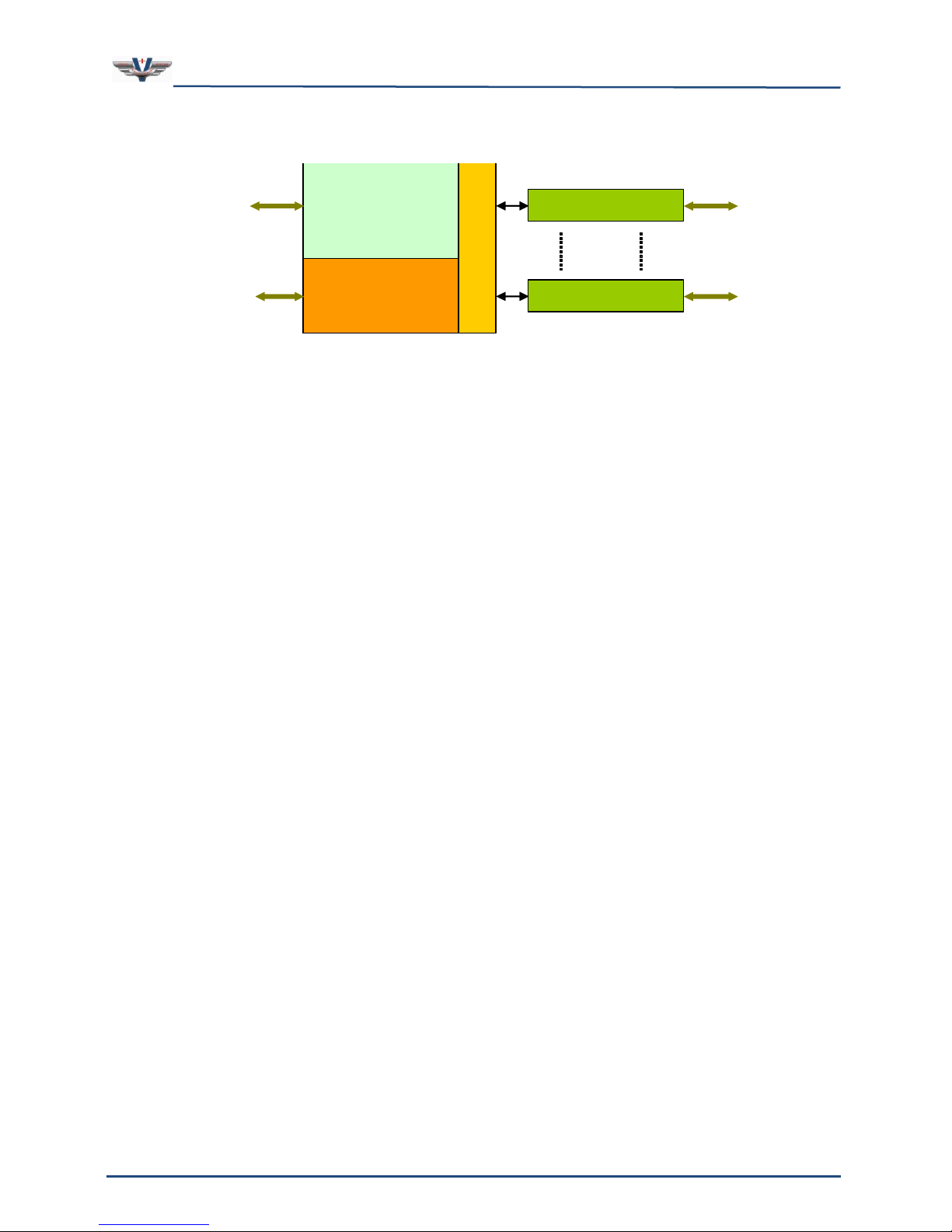
Figure 1 shows a simplified overall view of the system. A CPU powers the system and runs
the visual programming software, V+, which controls all aspects of the system. Audio
signals are connected to the system via ¼” phone plugs on the breakout boxes. Each
breakout box features eight inputs and eight outputs, and one (1) system chassis can
support up to eight breakout boxes for a total of 64 inputs and 64 outputs. The flexibility of
SMx Audio System User's Manual, V1.41
SimPhonics, Inc.
Page 14 of 77
Page 14 of 77
Copyright © 2014 SimPhonics, Incorporated, All Rights Reserved
the SMX system allows any configuration from one (1) to eight (8) external boxes resulting
in 8 to 64 channels.
CPU
CPU
BREAKOUT BOXES
I/O Device
Drivers
INTERFACES
BREAKOUT BOXES
AUDIO
S
M
x
D
S
P
Figure 1, SMx System Architecture
The interfaces shown in the figure above refer to a variety of connections that can be one or
more Ethernet connections, and or I/O devices that have their own interfaces specific to
their type. For example, a typical system may have a DIS/HLA Ethernet connection and a
Host Ethernet interface. For now, let’s focus on the audio architecture.

SMx Audio System User's Manual, V1.41
SimPhonics, Inc.
Page 15 of 77
Page 15 of 77
Copyright © 2014 SimPhonics, Incorporated, All Rights Reserved
3.1 Overall System Block Diagram
Figure 2 illustrates an overall system block diagram for a standard 32 Channel system. The
delivered components are shown in separate colors. The computer chassis connects to a
Host computer via Ethernet, which commands the system via real-time data. This data
controls a V+ design, which generates sounds via the SMx system and output rack. This
diagram represents our standard 32 Channel configuration, PN: SMx-32-Enn-RM4.
Motherboard
Ethernet
Network
SMx
DSP Card
Computer Chassis
Keyboard,
Monitor,
and Mouse
Network
Interface Card
Analog Inputs
and
Analog Outputs
BREAK-OUT BOX
SMx
DSP Card
BREAK-OUT BOX
BREAK-OUT BOX
BREAK-OUT BOX
Figure 2, Overall System Block Diagram
SMx Audio System User's Manual, V1.41
SimPhonics, Inc.
Page 16 of 77
Page 16 of 77
Copyright © 2014 SimPhonics, Incorporated, All Rights Reserved
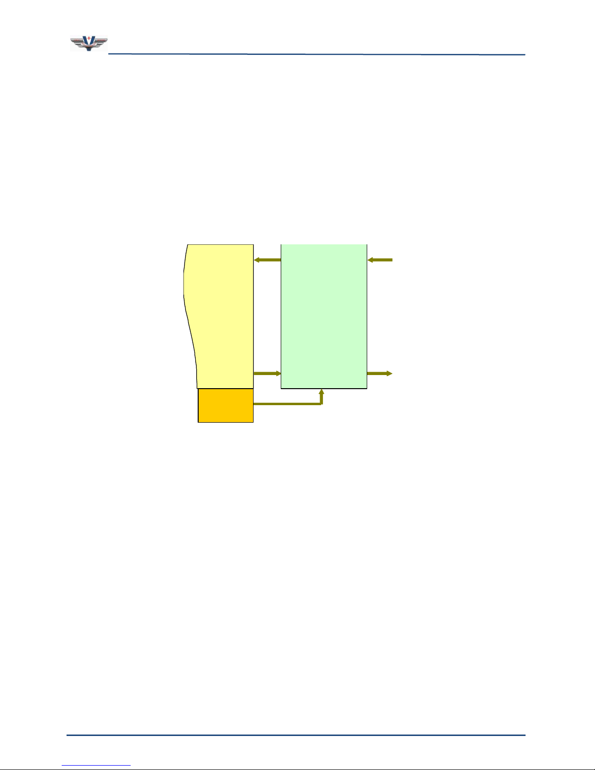
3.2 SMx Audio System
Figure 3 is a top level flow diagram of the AIs to WIs, and WOs to AOs. This is the heart of
the SMx audio system. Analog inputs and outputs flow to and from the Super Mixer, which is
also connected to the Wave inputs and Wave outputs of the Windows operating system. Our
SMx architecture is conceptually the same as an ordinary sound card for Windows, except
that there are many more channels of audio. The Super Mixer is controlled in V+ via the
“SMx Audio System” I/O driver.
The Super Mixer is a kernel level driver embedded within the Windows operating system. It
directly controls the SMx DSP cards which are connected to the breakout boxes. It can route
audio streams in almost any fashion. In order to understand SMx, it is essential to
understand the Super Mixer operation. Each line in the diagram can actually be 64 discrete
channels. Note that breakout boxes are not shown for clarity.
AO
AI
WI
WO
Windows
Audio System
(DirectX)
SMx
Super Mixer
V+ SMx
I/O Driver
Figure 3, SMx Audio System

SMx Audio System User's Manual, V1.41
SimPhonics, Inc.
Page 17 of 77
Page 17 of 77
Copyright © 2014 SimPhonics, Incorporated, All Rights Reserved
3.3 SMx Super Mixer
The Super Mixer is the key to the flexibility of SMx. This is what enables SMx to be used in
applications where normal sound cards cannot. Let’s take a look at how this works. There
are four basic audio signal paths in the Super Mixer (refer to Figure 4):
1. Analog In to Analog Out –Input signals applied to the AIs are routed through the
input gain block, monitored at the AIn metering interface, mixed to AOs by the
Analog In to Analog Out mixer, routed through the output gain block, monitored at
the AOut metering interface and sent to the AOs.
2. Analog In to Wave In –Input signals applied to the AIs are routed through the
input gain block, monitored at the AIn metering interface, mixed to WIs by the
Analog In to Wave In mixer, and sent to the WIs of the Windows audio system.
3. Wave Out to Wave In –WO signals coming from the Windows audio system are
mixed to WIs in the Wave Out to Wave In mixer, and sent to the WIs of the Windows
audio system.
4. Wave Out to Analog Out –WO signals coming from the Windows audio system are
mixed to AOs in the Wave Out to Analog Out mixer, monitored at the WOut metering
interface, routed through the output gain block, monitored at the AOut metering
interface and sent to the AOs.
This mixer is a 64-channel system. That is, all of the lines connecting these mixer
components are 64 channels of audio. Even if your system has less than 64 channels of
physical audio, all 64 signals are mixed. The user can adjust the number of WO and WI
channels that are present in any SMx system. Keep in mind however, more channels means
more processing power needed to perform the Super Mixer calculations. Modern processors
have no problem with a full 64 channel super mixer requiring less than 8 percent of the
overall CPU.
Figure 4, SMx Super Mixer
SMx Audio System User's Manual, V1.41
SimPhonics, Inc.
Page 18 of 77
Page 18 of 77
Copyright © 2014 SimPhonics, Incorporated, All Rights Reserved
Each of the components shown in the figure above are represented in V+ as an I/O device.
Each of these I/O devices is explained further in sections below.
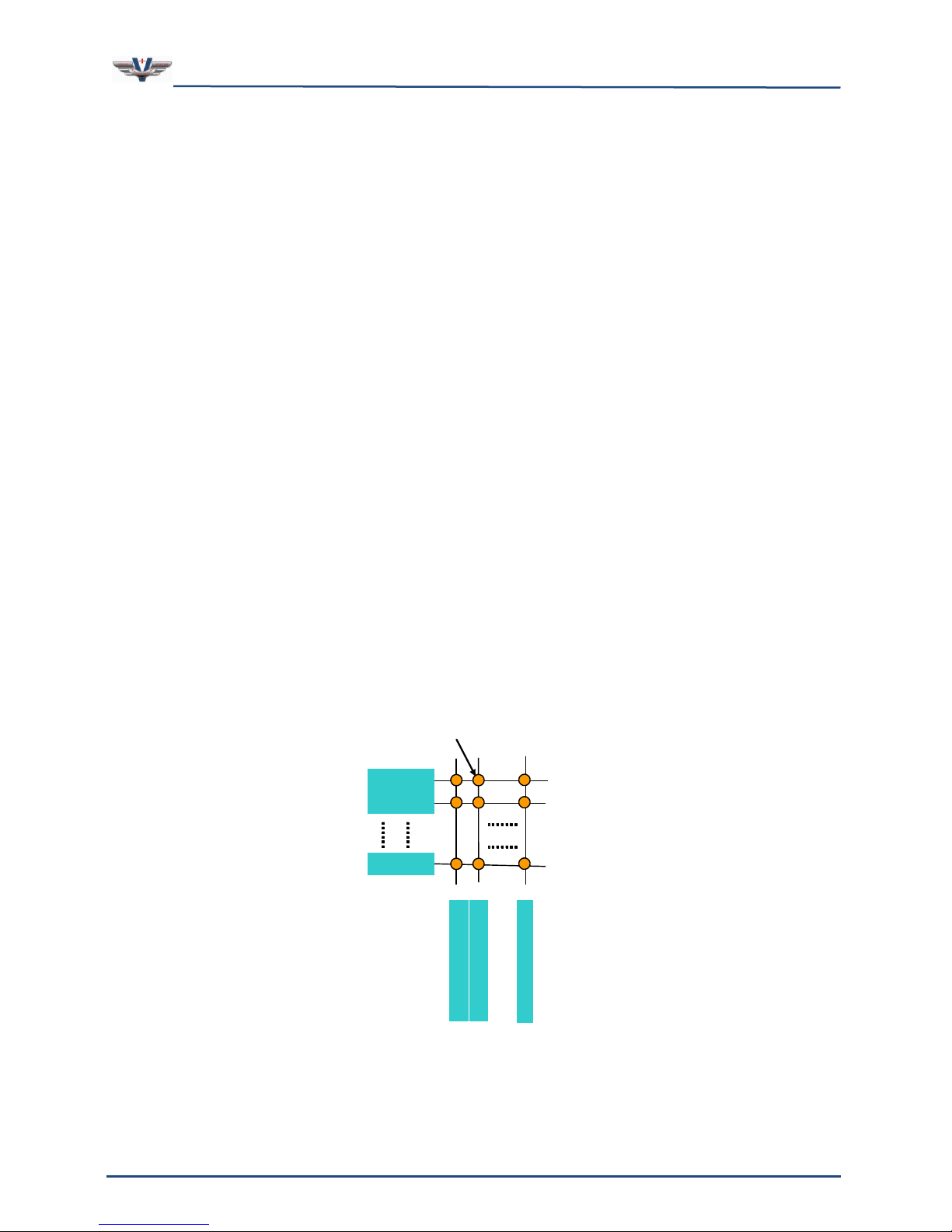
3.4 Individual Mixers
A mixer is a device used to mix audio signals from inputs to outputs. In order to remain
flexible, the mixer must be able to mix any input to any output independently without
affecting any other inputs or outputs. This is accomplished via a XY matrix of gain controls.
To further understand the generic mixer model, refer to Figure 5 below. The diagram shows
a matrix of lines, 64 horizontal and 64 vertical, with a circle at the intersection of each
horizontal and vertical line. For the sake of this discussion, let each horizontal line represent
an input to the mixer and each vertical line represent an output. The circles at the
intersections, then, would represent the gain values that are used to control the signal flow
from input to output.
The output signal is then computed as the summation of all input signals multiplied by the
respective gain values for that output. Each gain value (as represented by the circles in the
diagram) in the mixer has a corresponding port in V+ that can be given a value from 0.0 to
1.0.
There are four mixers in the SMx Super Mixer (see the tan boxes in Figure 4). The mixer
shown in the figure below is the Analog In to Analog Out Mixer. The mixers and the V+ I/O
devices that control them are discussed later.
As you can see, there a lot of V+ ports needed to control this mixer. In fact there are 64 X
64, or 4,096 ports per mixer, and there are four of them! If this mixer was exposed as a
hardware mixer to Windows XP and there were controls for each gain cell, there would be
over 16,384 controls present on the mixer console.
AI 1
AI 2
AI 64
A
O
1
A
O
2
A
O
6
4
AI 1 to AO 2
Figure 5, SMx Mixer Matrix

SMx Audio System User's Manual, V1.41
SimPhonics, Inc.
Page 19 of 77
Page 19 of 77
Copyright © 2014 SimPhonics, Incorporated, All Rights Reserved
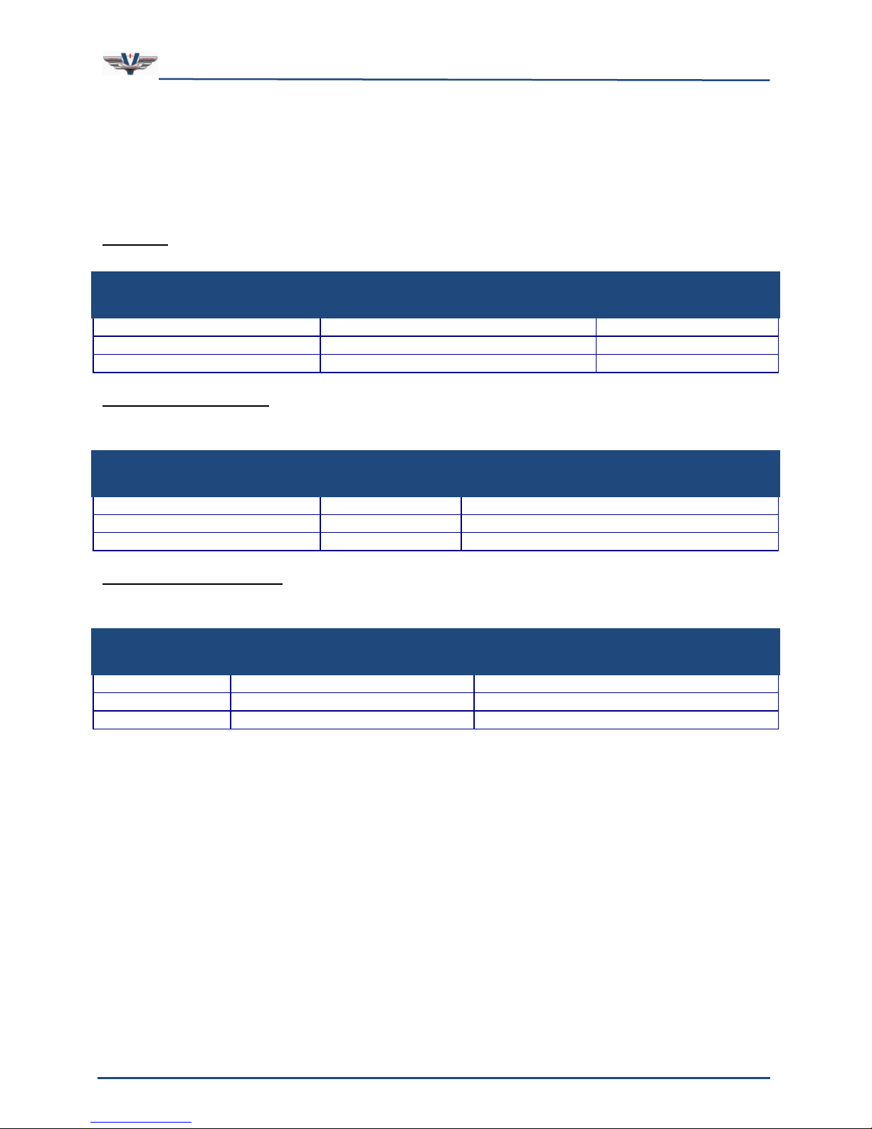
3.5 Individual Mixer Module
There are four mixer modules in the SMx super mixer and each one contains 4,096 gain
controls that are exposed as a port in V+. The entire SMx super mixer contains 4 X 4,096
or 16,384, + (5) more gain block and meter sections of 64 ports each, resulting in 16,704
V+ ports under CPU control. There is no other mixer like this on planet earth.
Figure 6, Single SMx Mixer Module Showing all 4,096 Gain Controls
SMx Audio System User's Manual, V1.41
SimPhonics, Inc.
Page 20 of 77
Page 20 of 77
Copyright © 2014 SimPhonics, Incorporated, All Rights Reserved
4Hardware
4.1 Specifications
Physical
All components shown in the Table 1 are standard 19” EIA rack-mountable units.
Table 1. SMx Physical Specifications
SMx Component
Dimensions (Inches)
Weight (Pounds)
2U System Chassis
3.465H x 19W x 25.6D
31
4U System Chassis
7.00H x 19W x 20.5D
40
SMx Breakout Box
1.5H X 19W X 6D
3
Power Requirements
All components shown in Table 2 are designed to operate from US or European power
systems. The SMx Breakout Box power supply is CE certified.
Table 2. SMx Power Requirements
SMx Component
Current
Voltage
2U System Chassis
6 / 3 A
90-264VAC (Auto Switching), 47-63Hz
4U System Chassis
10 / 5 A
100- 240 VAC (Auto Switching), 47-63Hz
SMx Breakout Box
1.5 / .75A
90-264VAC (Auto Switching), 47-63Hz
Operating and Storage
Table 3 lists the operating and storage conditions for the SMx Audio System. Note: These
specifications are for the SMx system without a keyboard, monitor and mouse.
Table 3. Operating and Storage Conditions
Category
Operating
Storage
Temperature
0°C to 40°C
-20°C to 60°C
Altitude
0 to 10,000 Feet
0 to 40,000 Feet
Humidity
20% to 90% (Non-condensing)
5% to 95% (Non-condensing)
Table of contents


 operating instructions")


