Simple CarConnect Installation instructions

CarConnect
Bluetooth Interface
Installation Manual
Page 2
CarConnect
Smartphone Integration Interface
Installation/Owner’s Manual
Table of Contents
1. Wiring Overview
2. GM Vehicles - Page 3
3. Honda/Acura Vehicles - Pages 3-4
4. Toyota/Lexus/Scion - Page 4-5
5. Connecting the Factory Satellite Radio Tuner Accessory Wire (PGHSATR) - Page 6
6. Testing & Verication - Page 7
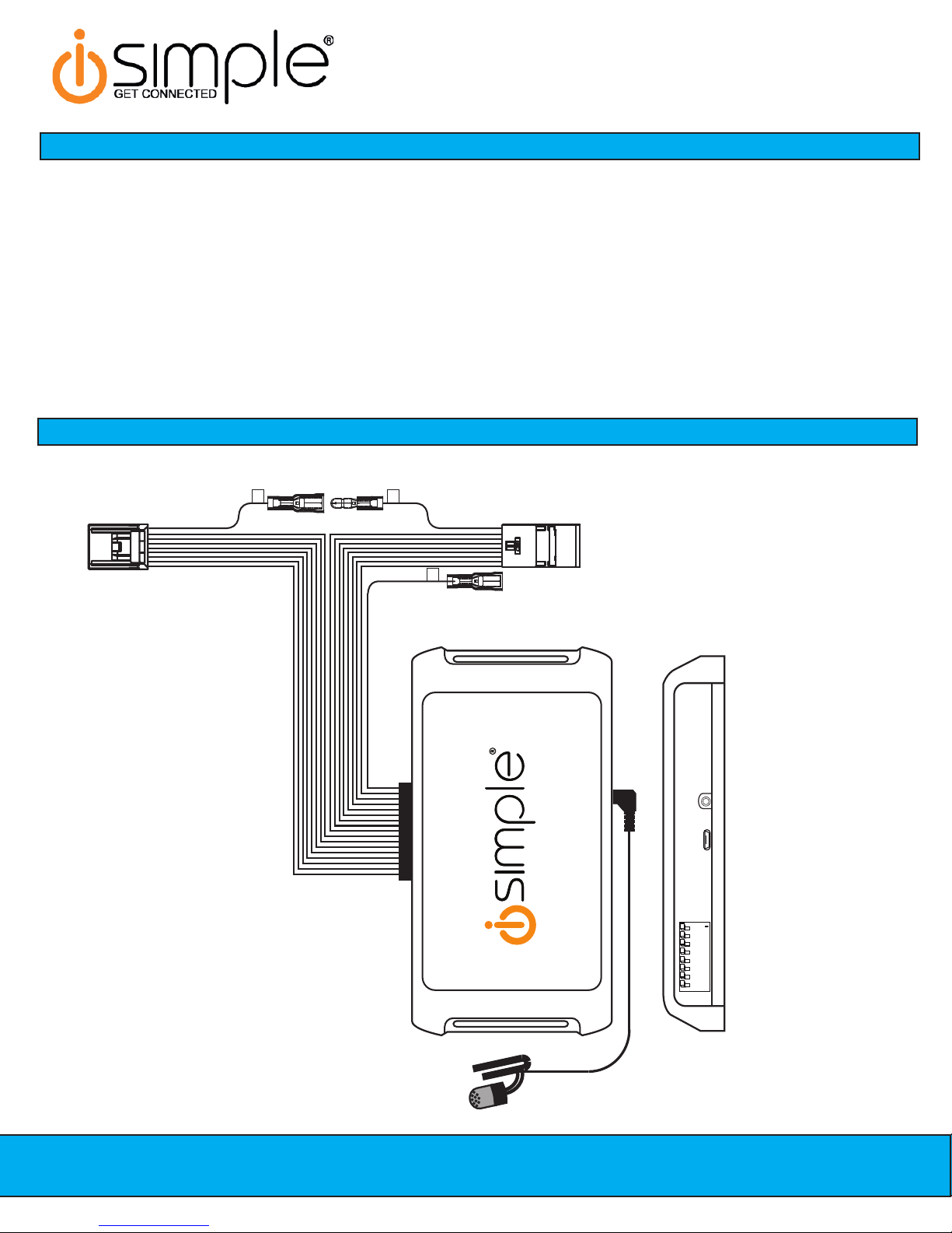
Wiring Overview
1
DIP ON
2345678
Vehicle Dipswitches
USB Port
Microphone Input
A
B
C
CarConnect
Smartphone Integration Interface
Installation/Owner’s Manual
Page 2 Page 3
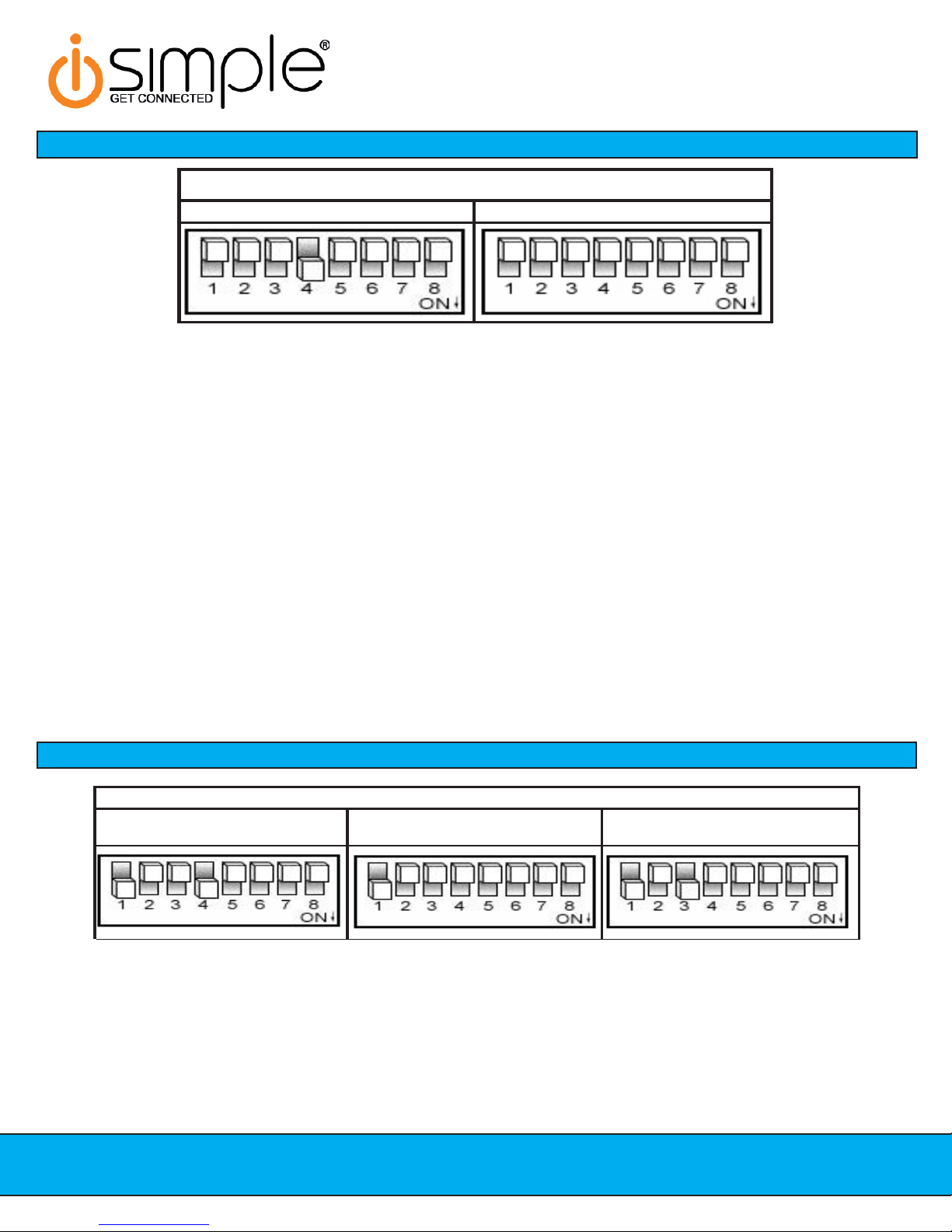
GM Vehicles
EscaladeNonNav AllOtherVehicles
1. Set the dipswitches on the CarConnect interface as indicated above.
2. Carefully remove the trim panels & bolts that secure the radio into the dash cavity. Carefully pull the radio from the dash of the
vehicle. This will provide access to the factory radio connectors where you will connect the CarConnect harness.
3. Select the location where the microphone will be mounted. This location will vary based on the vehicle and the customer’s
preference. Once mounted, carefully run the microphone cable behind the radio to the CarConnect. When running this cable
through the dash be sure to secure it away from moving parts or sharp metal edges that may damage the cable. Insert the
3.5mm microphone jack into the port on the CarConnect.
4. Disconnect the factory 16-Pin harness and 14-Pin harness from the back of the radio.
5. Plug in the male connectors on the PGHGM1 harness into the 16-pin port and 14-pin port on the back of the radio. Next,
connect the factory 16-pin and 14-pin connectors into the female connectors on the PGHGM1 harness. Be sure to make a
rm connection but do not force it. Plug the Black micro-t 24-pin connector on the PGHGM1 harness into the CarConnect
Interface.
6. To complete the installation secure the CarConnect into the cavity in the dash behind the radio. Be sure that the cables and
interface modules are not near moving parts or sharp metal edges as they may damage the cables. To prevent rattling noises
inside the dash, use zip ties, tape, or other fasteners to mount the interface securely.
7. With all connections made, insert the key into the ignition, and turn the vehicle on. Check for proper operation of the
CarConnect before reinstalling the factory dash panels (see pg. 7 for test and verication section).
Honda/Acura Dipswitch Settings
Honda/Acura Vehicles
1. Set the dipswitches on the CarConnect interface as indicated above.
2. Carefully remove the trim panels & bolts that secure the radio into the dash cavity. Carefully pull the radio from the dash of the
vehicle. This will provide access to the factory radio connectors where you will connect the CarConnect harness.
3. Select the location where the microphone will be mounted. This location will vary based on the vehicle and the customer’s
preference. Once mounted, carefully run the microphone cable behind the radio to the CarConnect. When running this cable
through the dash be sure to secure it away from moving parts or sharp metal edges that may damage the cable. Insert the
3.5mm microphone jack into the port on the CarConnect.
ill differ by vehicle but can ususally be found in the rear of the vehicle.
Page 4
CarConnect
Smartphone Integration Interface
Installation/Owner’s Manual
Toyota/Lexus/Scion Vehicles
Honda/Acura Vehicles (cont.)
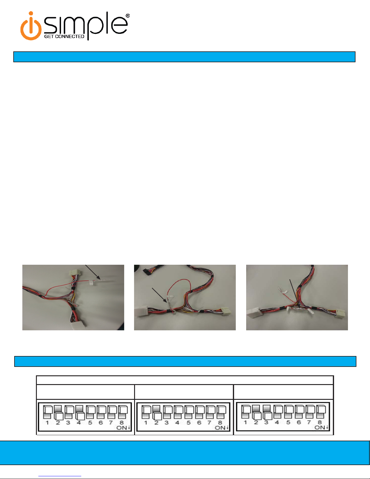
Fig. 1 Fig. 2 Fig. 3
Connect PGHSATR Wire to C Here Connect B to C Here Leave A connected to B Here
4. Disconnect the factory 14-Pin harness (if present) from the back of the radio.
5. Prepare the CarConnect harness for installation. Depending on what factory peripherals you have in your vehicle, you may
need to make changes to the red wire with bullet connectors on them.
A. Vehicles equipped with factory Satellite Radio + other Peripherals (Rear Seat Entertainment, CD Changer, etc...):
Connect the supplied PGHSATR wire to the bullet connector labeled “C” coming off of the 24-pin CarConnect connector.
(Fig.1) Run this wire to the factory satellite tuner and connect as outlined on page 6. Factory satellite tuner locations
B. Vehicles equipped with only factory Satellite Radio: Disconnect the bullet connectors labeled A & B on the
PGHHD1R harness. Connect the bullet connector labeled “B” on the vehicle side of the PGHHD1R harness to the bullet
connector labeled “C” coming off of the 24-pin CarConnect harness (Fig. 2).
C. Vehicles equipped with no factory peripherals: Leave all bullet connectors as they are out of the box (A connected to
B) No modications are necessary. (Fig. 3)
5. Plug in the male connector on the PGHHD1R harness into the14-pin port on the back of the radio. Next, connect the factory
14-pin connector (if present) into the female connector on the PGHHD1R harness. Be sure to make a rm connection but do
not force it. Plug the Black micro-t 24-pin connector on the PGHHD1R harness into the CarConnect Interface.
6. To complete the installation secure the CarConnect into the cavity in the dash behind the radio. Be sure that the cables and
interface modules are not near moving parts or sharp metal edges as they may damage the cables. To prevent rattling noises
inside the dash, use zip ties, tape, or other fasteners to mount the interface securely.
7. With all connections made, insert the key into the ignition, and turn the vehicle on. Check for proper operation of the
CarConnect before reinstalling the factory dash panels (see pg. 7 for test and verication section).

CarConnect
Smartphone Integration Interface
Installation/Owner’s Manual
Page 4 Page 5
. Set the dipswitches on the CarConnect interface as indicated on Page 4.
. Carefully remove the trim panels & bolts that secure the radio into the dash cavity. Carefully pull the radio from the dash of the
vehicle. This will provide access to the factory radio connectors where you will connect the CarConnect harness.
. Disconnect the factory 12-Pin harness (if present) from the back of the radio.
. Select the location where the microphone will be mounted. This location will vary based on the vehicle and the customer’s
preference. Once mounted, carefully run the microphone cable behind the radio to the CarConnect. When running this cable
through the dash be sure to secure it away from moving parts or sharp metal edges that may damage the cable. Insert the
3.5mm microphone jack into the port on the CarConnect.
. Prepare the CarConnect harness for installation. Depending on what factory peripherals you have in your vehicle, you may
need to make changes to the red wire with bullet connectors on them.
A. Vehicles equipped with factory Satellite Radio + other Peripherals (Rear Seat Entertainment, CD Changer, etc...):
Connect the supplied PGHSATR wire to the bullet connector labeled “C” coming off of the 24-pin CarConnect connector.
(Fig.1) Run this wire to the factory satellite tuner and connect as outlined on page 6. Factory satellite tuner locations will
differ by vehicle but can ususally be found in the rear of the vehicle.
B. Vehicles equipped with only factory Satellite Radio: Disconnect the bullett connectors labeled A & B on the
PGHHD1R harness. Connect the bullett connector labeled “B” on the vehicle side of the PGHHD1R harness to the bullett
connector labeled “C” coming off of the 24-pin CarConnect harness (Fig. 2).
C. Vehicles equipped with no factory peripherals: Leave all bullett connectors as they are out of the box (A connected to
B). No modifications are necessary. (Fig. 3)
. Plug in the male connector on the PGHTY1R harness into the12-pin port on the back of the radio. Next, connect the factory12-
pin connector (if present) into the female connector on the PGHTY1R harness. Be sure to make a firm connection but do not
force it. Plug the Black micro-fit 24-pin connector on the PGHTY1R harness into the CarConnect Interface.
. To complete the installation secure the CarConnect into the cavity in the dash behind the radio. Be sure that the cables and
interface modules are not near moving parts or sharp metal edges as they may damage the cables. To prevent rattling noises
inside the dash, use zip ties, tape, or other fasteners to mount the interface securely.
. With all connections made, insert the key into the ignition, and turn the vehicle on. Check for proper operation of the
CarConnect before reinstalling the factory dash panels (see pg. 7 for test and verification section).
Fig. 1 Fig. 2 Fig. 3
Connect PGHSATR Wire to C Here Connect B to C Here Leave A connected to B Here
Toyota/Lexus/Scion Vehicles (Cont.)

side of the accessory input wire. The procedure outlined below is specically for a Honda Odyssey and will vary by vehicle.
Page 6
CarConnect
Smartphone Integration Interface
Installation/Owner’s Manual
Connecting the Satellite Radio Tuner Accessory Wire
**PLEASE NOTE: This only needs to be done in vehicles which have multiple factory peripherals such as
Satellite Radio, Rear Seat Entertainment & a CD Changer**
In some vehicles you will need to access the factory satellite radio tuner and connect the supplied PGHSATR wire to the tuner
Remove the bottom rear panel Remove the spare tire cover and tie
down holder
Remove the spare tire
It should now look like this. Pull on
the panel from the back edge to
release it.
The satellite tuner connector is
behind the plastic
Pull back the plastic and access the
satellite tuner plug
The wire you need to cut and
connect to is Blue/Red in pin 2
Make the connection as shown here
using the supplied crimp connector.
Insulate and secure the other side of
the wire.

CarConnect
Smartphone Integration Interface
Installation/Owner’s Manual
Page 6 Page 7
This device complies with Part 15 of the FCC Rules. Operation is subject to the following two conditions:
(1) this device may not cause harmful interference, and
(2) this device must accept any interference received, including interference that may cause undesired operation.
Changes or modications not expressly approved by the party responsible for compliance could void the user’s authority to operate the
equipment.
NOTE: This equipment has been tested and found to comply with the limits for a Class B digital device, pursuant to Part 15 of the FCC Rules.
These limits are designed to provide reasonable protection against harmful interference in a residential installation. This equipment gener-
ates, uses and can radiate radio frequency energy and, if not installed and used in accordance with the instructions, may cause harmful
interference to radio communications.
However, there is no guarantee that interference will not occur in a particular installation. If this equipment does cause harmful interference to
radio or television reception, which can be determined by turning the equipment off and on, the user is encouraged to try to correct the interfer-
ence by one or more of the following measures:
FCC Statement
- Reorient or relocate the receiving antenna.
- Increase the separation between the equipment and receiver.
- Connect the equipment into an outlet on a circuit different from that to which the receiver is connected.
- Consult the dealer or an experienced radio/TV technician for help.
Testing & Verication
1. Turn the ignition on.
2. Switch the radio to the XM or CD Changer source (depending on how you have the CarConnect configured).
3. Pair your phone with the CarConnect. The CarConnect should be discoverable after the install. If it is not, follow the
proce-dure listed below for your mode of operation to make the CarConnect discoverable.
•Satellite Radio Operation: Press Preset 5 five times to make the CarConnect discoverable.
•CD Changer Operation: Press the Repeat or Scan button five times to make the CarConnect discoverable.
4. Verify that the interface streams audio and passes hands free audio.
5. Check the controls based on your protocol specific instructions.
Learn more about bluetooth car kits on our website.
Other manuals for CarConnect
1
Table of contents
Other Simple Recording Equipment manuals

Popular Recording Equipment manuals by other brands

Rane
Rane ME 60S Operator's manual

Mutable Instruments
Mutable Instruments Links user manual

Simplex
Simplex 4100 Series installation instructions

Dictaphone
Dictaphone Walkabout Express operating instructions

Toshiba
Toshiba RBM-Y0384FUL installation manual

IFM Electronic
IFM Electronic AC2482 operating instructions


