Simplex 4100 Series User manual

574-050 Rev. N
4100/4120-Series VESDA Interface Cards Installation Instructions
*0574050N*
Cautions, warnings, and regulatory information
READ AND SAVE THESE INSTRUCTIONS Follow the instructions in this installation manual. These instructions must be followed to avoid damage to
this product and associated equipment. Product operation and reliability depend upon proper installation.
DO NOT INSTALL ANY SIMPLEX™ PRODUCT THAT APPEARS DAMAGED Upon unpacking your Simplex product, inspect the contents
of the carton for shipping damage. If damage is apparent, immediately file a claim with the carrier and notify an authorized Simplex
product supplier.
ELECTRICAL HAZARD Disconnect electrical field power when making any internal adjustments or repairs. All repairs should be
performed by a representative or an authorized agent of your local Simplex product supplier.
STATIC HAZARD Static electricity can damage components. Handle as follows:
• Ground yourself before opening or installing components.
• Prior to installation, keep components wrapped in anti-static material at all times.
FCC RULES AND REGULATIONS – PART 15. This equipment has been tested and found to comply with the limits for a Class A digital device,
pursuant to Part 15 of the FCC Rules. These limits are designed to provide reasonable protection against harmful interference when the equipment
is operated in a commercial environment. This equipment generates, uses, and can radiate radio frequency energy and, if not installed and used in
accordance with the instruction manual, may cause harmful interference to radio communications. Operation of this equipment in a residential area is
likely to cause harmful interference in which case the user will be required to correct the interference at his own expense.
Introduction
This publication describes the installation procedure for the 4100-0154/4120-0154 and 4100-6048 VESDA Interface modules. This document covers
the following topics:
• Configuring, wiring, and installing a VESDA RS-232 Interface card in a 4100/4100U/ 4100ES FACP.
• Adding supervisory wiring to a VESDA power supply. This wiring is only required for VESDA power supplies, and is not required if VESDA
detectors are powered by 4100 power supplies.
Related documentation
•VESDA Installation Sheet: This document ships with the detector, and gives basic instructions on installing, wiring, and powering up the detector.
This is also available from the Xtralis Extranet site.
•VESDA Product Guide: This document is available from the Xtralis Extranet site, and gives a more detailed guide on installation, wiring, powering,
and maintaining the detector.
•VESDA LCD Programmer Product Guide: This document is available from the Xtralis Extranet, and documents how to program using the LCD
Programmer. The methods described are also used with the high level interface (HLI)
•VESDA Intelligent Interface, Operating, and Programming Manual,
•Field Wiring Diagram for 4100 Power Limited (841-731) or Field Wiring Diagram for Non Power Limited (841-995)
•4100ES Fire Alarm System Installation Guide (574-848)
page 2 574-050 Rev. N
4100/4120-Series VESDA Interface Cards Installation Instructions
Setting jumpers
Verifying jumper settings
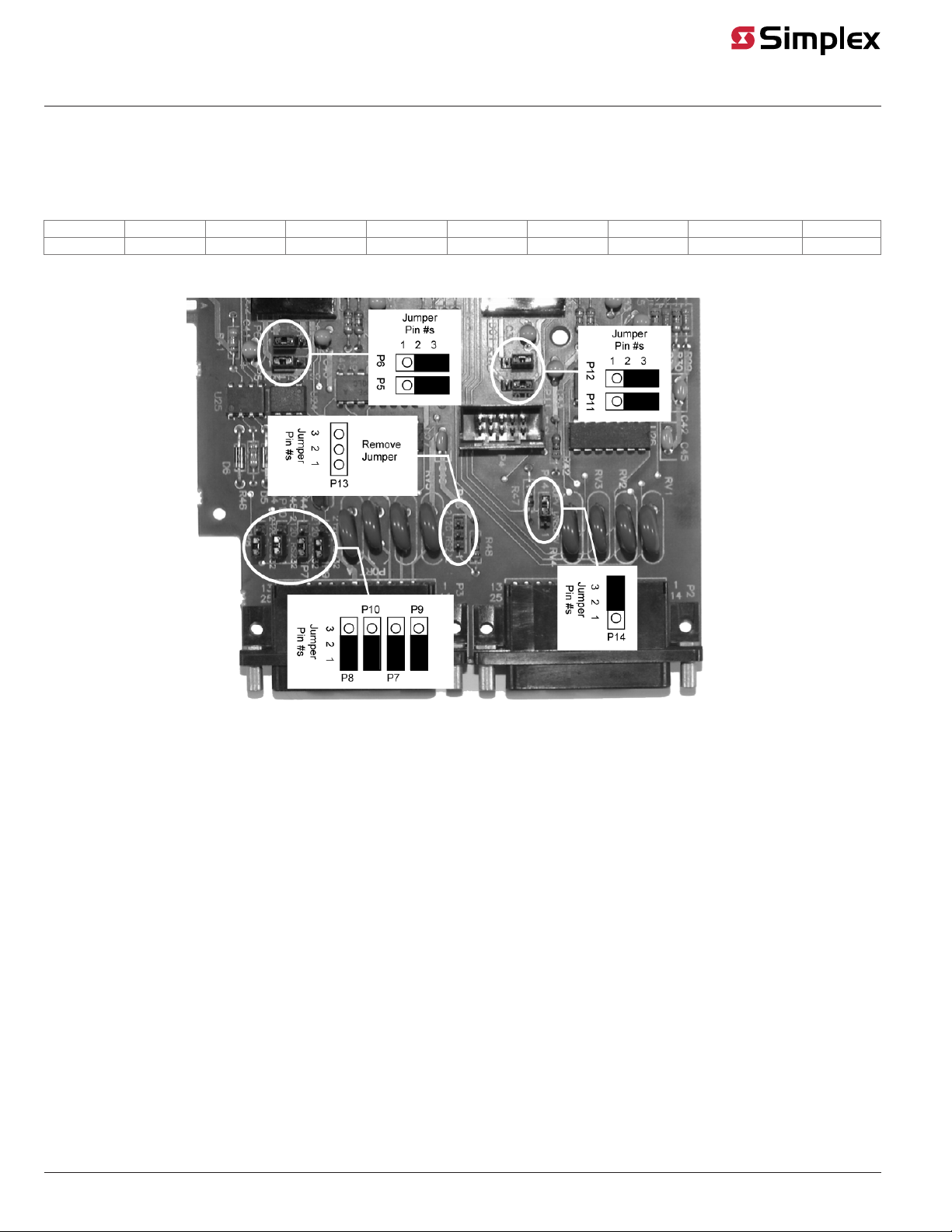
All jumpers on the VESDA RS-232 interface daughter card are factory preset and do not require modification. If necessary, use this section to verify that
the jumpers are in the correct positions. See Table 1 and Figure 1.
Table 1: VESDA default jumper settings
P5 P6 P7 P8 P9 P10 P11 P12 P13 P14
2-3 2-3 1-2 1-2 1-2 1-2 2-3 2-3 Remove Jumper 2-3
In the table above, 2-3 means you should place the jumper on pins 2 and 3, whereas a designation of 1-2 means you should place the jumper on pins
1 and 2.
Figure 1: Jumper settings for VESDA RS-232 interface card

page 3 574-050 Rev. N
4100/4120-Series VESDA Interface Cards Installation Instructions
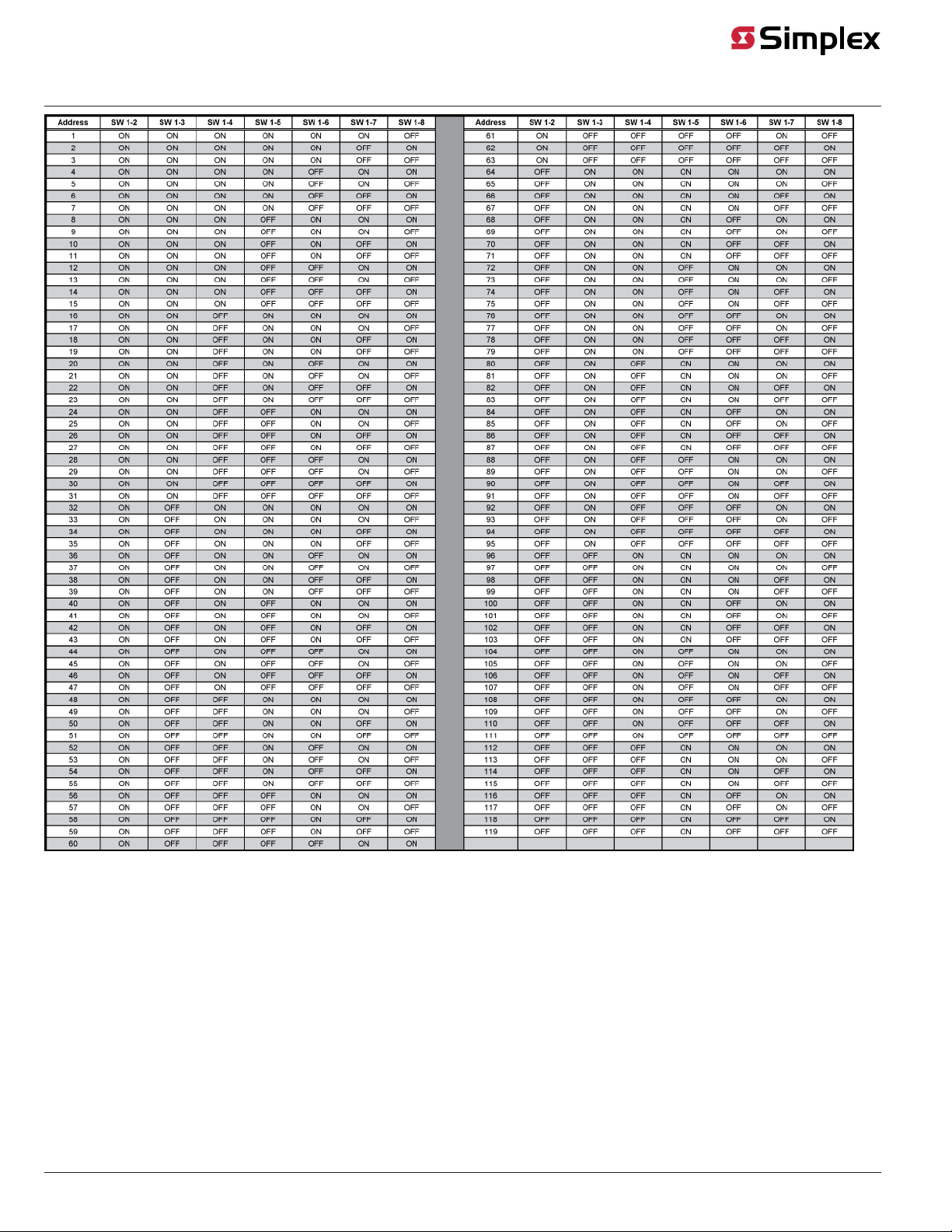
Setting switches
Switch SW1 on the VESDA RS-232 interface daughter card is a bank of eight dip switches. From left to right (Figure 2) these switches are designated as
SW1-1 through SW1-8. The function of these switches is as follows:
• SW1-1 sets the baud rate for the serial communication line running between the VESDA RS-232 interface card and the 4100 CPU. Set this
switch to ON.
• SW1-2 through SW1-8 set the card address within the 4100 FACP. These switches must be set to the value assigned to the card by the
Programmer. See Figure 3 for a complete list of the switch settings for all of the possible card addresses.
Figure 2: Jumper settings for the VESDA RS-232 interface card
page 4 574-050 Rev. N
4100/4120-Series VESDA Interface Cards Installation Instructions
Figure 3: 4100 Daughter card addresses

page 5 574-050 Rev. N
4100/4120-Series VESDA Interface Cards Installation Instructions
Installing the Motherboard into 2975-91xx Back Boxes (4100)
The VESDA motherboard can be mounted to either 4100 Back Boxes (PID series 2975-91xx) or 4100U/4100ES Back Boxes (PID series 2975-94xx).
• The 4100-0154/4120-0154 is used for systems with 4100 Back Boxes.
• The 4100-6048 is used for systems with 4100U /4100ES Back Boxes
This section describes mounting the 4100-0154/4120-0154 version into 4100 Back Boxes.
Installing in a 2975-91xx Master Controller Bay
Use the following guidelines and instruction when installing into a master controller bay.
• If the 575-274 Master Motherboard is used, it must be installed in the leftmost position of this bay. If the 575-274 Master Motherboard is not
used, the CPU motherboard must be installed in the leftmost position of the bay.
• The power supply must be installed in the rightmost position of the bay.
• Relay cards must be installed in the slots immediately to the left of the power supply. This is necessary to allow for the proper routing of
nonpower limited wiring (120 VAC wiring connected to the relay card).
• If used, the Class B motherboard (575-275) must be installed to the left of the relay cards. If a physical bridge is used with the Class B
motherboard, it must be to the right of any motherboards using NICs. This allows for earth ground detection via the physical bridge. Install the
motherboard as described below.
To install the motherboard complete the following steps:
1. Orient the motherboard so that the connector labeled J1 is on the right and the header labeled P1 is on the left.
2. Slide the motherboard you are installing to the left until the pins are completely inserted in the connector of a previously installed
motherboard.
3. Secure the motherboard to the chassis with four Torx screws.
You can install the motherboard in any of these slots. If the bay has relay cards, install them to the immediate left of the power supply.
Figure 4: Installing the Motherboard into a 4100 Master Controller Bay

page 6 574-050 Rev. N
4100/4120-Series VESDA Interface Cards Installation Instructions
Installing into a 2975-91xx Expansion Bay
Review the following guidelines before mounting the motherboard into a 2975-91xx Expansion Bay.
• If a power supply is installed in the bay, it must be installed on the far right of the bay and any relay modules must be installed in the slots
immediately to its left.
• Relay cards must be installed in the rightmost possible slots. This is necessary to allow for the proper routing of non-power limited wiring
(typically 120 VAC wiring), which could be connected to a relay module.
• If a 4100-0155 /4120-0155 SDACT, 4100-6052 Event Reporting DACT, 4100-6053 Point Reporting DACT, or a 4100-0153 / 4120-0153 CCDACT
is installed in the bay, it must be installed in the far left or far right slot. Neither of these modules contains the J1 or P1 connectors, which are
used to distribute power and communications to adjacent modules.
Use the following directions and Figure 5 to install a motherboard into an expansion bay.
1. Orient the motherboard with the connector labeled J1 on the right and the header labeled P1 on the left.
2. Match the connector on the previously installed motherboard with the pins on the motherboard you are installing. Slide the motherboard
to the left until the pins are completely inserted in the connector of the previously installed motherboard. If you are installing the leftmost
board, the pins will remain unconnected.
3. Secure the motherboard to the chassis with four torx screws.
The motherboard can be installed in any of the eight slots. If the bay has relay cards, they must be installed on the far right of the bay.
Figure 5: Installing the Motherboard into a 4100 Expansion Bay
4. If you are installing the leftmost motherboard, connect a 733-525 Power and Communication Harness. Continue to the next topic to connect
the harness.

page 7 574-050 Rev. N
4100/4120-Series VESDA Interface Cards Installation Instructions
Connecting the 733-525 Harness
If you need to connect a 733-525 Harness to a motherboard, refer to Figure 5 and follow these steps. Make sure to route the power and
communication wiring on the left side of the bay.
1. Connect one end of the harness to a motherboard in an adjacent bay. If the adjacent bay is a master controller bay, connect the harness to
the P2 and P3 connectors of the master controller motherboard and continue to step 2. If the adjacent bay is an expansion bay, connect the
harness to the P2 and P3 connectors of the motherboard installed in the leftmost slot. (If a 4100-0155 /4120-0155 SDACT, 4100-6052 Event
Reporting DACT, 4100-6053 Point Reporting DACT, or a 4100-0153 /4120-0153 CCDACT occupies the leftmost slot, connect the harness to
the motherboard in the second slot from the left.) Connect the harness as follows:
a. Insert the harness connector with the blue wire into the P2 connector. Note that the P2 connector has eight pins. Insert the harness
connector on either the top four pins or the bottom four pins, not in the middle.
b. Insert the harness connector with the white wire into the P3 connector. Note that the P3 connector has eight pins. Insert the harness
connector on either the top four pins or the bottom four pins, not in the middle.
2. Connect the other end of the harness to the leftmost motherboard in the next bay, as described below. Make sure to route the wiring on the
left side of the bay.
a. Insert the harness connector with the blue wire into the P2 connector. Note that the P2 connector has eight pins. Insert the harness
connector on either the top four pins or the bottom four pins, not in the middle.
b. Insert the harness connector with the white wire into the P3 connector. Note that the P3 connector has eight pins. Insert the harness
connector on either the top four pins or the bottom four pins, not in the middle.
Figure 6: Power and communication wiring for motherboards (4100)

page 8 574-050 Rev. N
4100/4120-Series VESDA Interface Cards Installation Instructions
Installing the Motherboards in 2975-94xx Back Boxes (4100U/4100ES)
The VESDA motherboard can be mounted to either 4100 Back Boxes (PID series 2975-91xx) or 4100U/4100ES Back Boxes (PID series 2975-94xx).
• The 4100-0154 4120-0154 is used for systems with 4100 Back Boxes.
• The 4100-6048 is used for systems with 4100U /4100ES Back Boxes.
This section describes mounting the 4100-6048 version into 4100U/4100ES Back Boxes.
Use the 4100-6048 for systems with 4100ES back boxes.
Installing in a 2975-94xx CPU bay
You can install up to two motherboards with the system CPU in the CPU bay.
To mount a motherboard into a CPU bay, complete the following steps:
1. Orient the motherboard with the connector labeled J1 on the right and the header labeled P1 on the left.
2. Slide the motherboard to the right until the pins from P1 on the motherboard to the right are completely inserted in the motherboard J1
connector.
3. Attach four lockwashers and metal standoffs to the chassis and secure the motherboard to the chassis using four #6 screws.
Figure 7: Installing the motherboard in a 4100U/4100ES CPU Bay
When installing 2 in. x 11 1/2 in. motherboards in a 4100U/4100ES expansion bay, adhere to the following guidelines:
• Each expansion bay assembly includes a chassis, two end supports, one LED/switch frame, and a power distribution interface (PDI) board.
• An expansion bay holds up to eight 4 in. x 5 in. modules. A double-size module, such as the ES-XPS/ES-PS, takes up two blocks of space as
shown in the following figure.
• You can install up to seven 2 in. x 11 11 1/2 in. motherboards in an expansion bay if no 4 in. x 5 in. modules are installed in the bay. You can
mount motherboards on top of the PDI in expansion bays. The data and power that would normally be bussed through the PDI is instead
routed across the boards through ribbon cable from one board to the next.
• As shown in Figure 8, you can install motherboards alongside 4 in. x 5 in. cards, if necessary.
• The leftmost slot must not contain a motherboard.
• You must add 4 in. x 5 in. cards right to left.
• You must add motherboards left to right.

page 9 574-050 Rev. N
4100/4120-Series VESDA Interface Cards Installation Instructions
Figure 8: Installing the motherboard in a 4100U/4100ES expansion bay
Use the following procedure when installing motherboards in an expansion bay. Start with the second slot from the left and fill to the right.
1. Orient the motherboard with the connector labeled J1 on the right and the header labeled P1 on the left
2. Attach four metal threaded standoffs and lockwashers into the screw holes on the chassis.
3. Attach two grey plastic standoffs to the motherboard socket mounting screws.
4. Secure the motherboard to the standoffs using four #6 torx screws as shown in Figure 9.
Figure 9: Installing the Motherboard in a 4100U/4100ES Expansion Bay
5. If you are installing the leftmost motherboard, connect a 733-525 Power and Communication Harness. Continue to the next topic to connect
the harness.

page 10 574-050 Rev. N
4100/4120-Series VESDA Interface Cards Installation Instructions
Connecting the 733-525 Harness
If you need to connect a 733-525 Harness to a motherboard, refer to Figure 10 and follow these steps. Make sure to route the power and
communication wiring on the left side of the bay.
1. Connect one end of the harness to a motherboard in an adjacent bay.
If the adjacent bay is a CPU bay with no additional motherboards, connect the harness to the P8 and P7 connectors of the CPU
motherboard.
- Insert the harness connector with the blue wire into the P8 connector. Note that the P8 connector has eight pins. Insert the harness
connector on either the top four pins or the bottom four pins, not in the middle.
- Insert the harness connector with the white wire into the P7 connector. Note that the P7 connector has eight pins. Insert the harness
connector on either the top four pins or the bottom four pins, not in the middle.
If the adjacent bay is an expansion bay or a CPU bay with additional motherboards, connect the harness to the P2 and P3 connectors of the
motherboard installed in the leftmost slot. (If a 4100-0155/4120-0155 SDACT, 4100-6052 Event Reporting DACT,4100-6053Point Reporting
DACT, or a 4100-0153 / CCDACT occupies the leftmost slot, connect the harness to the motherboard in the second slot from the left.)
Connect the harness as follows:
- Insert the harness connector with the blue wire into the P2 connector. Note that the P2 connector has eight pins. Insert the harness
connector on either the top four pins or the bottom four pins, not in the middle.
- Insert the harness connector with the white wire into the P3 connector. Note that the P3 connector has eight pins. Insert the harness
connector on either the top four pins or the bottom four pins, not in the middle.
2. Connect the other end of the harness to the leftmost motherboard in the next bay, as described below. Make sure to route the wiring on the
left side of the bay.
- Insert the harness connector with the blue wire into the P2 connector. Note that the P2 connector has eight pins. Insert the harness
connector on either the top four pins or the bottom four pins, not in the middle.
- Insert the harness connector with the white wire into the P3 connector. Note that the P3 connector has eight pins. Insert the harness
connector on either the top four pins or the bottom four pins, not in the middle.
Other manuals for 4100 Series
9
This manual suits for next models
1
Table of contents
Other Simplex Recording Equipment manuals

Simplex
Simplex 2100 User manual

Simplex
Simplex 4100-1340 User manual

Simplex
Simplex SafeLINC 4100-6060 Installation instructions

Simplex
Simplex 4100 Series User manual

Simplex
Simplex 4100-6062 Technical specifications

Simplex
Simplex 4100-6047 Assembly instructions

Simplex
Simplex VESDA 4100 Series User manual

Simplex
Simplex 2120 Reference guide


