General wiring guidelines
• Conductors must test free of all grounds.
• All wiring must be done using copper conductors only, unless
noted otherwise.
• The required wiring is unshielded Twisted Pair. This wiring must
have a capacitive rating of less than 60pf/ft and minimum 3 twists
(turns) per foot.
• • If shielded wire is used:
- The metallic continuity of the shield must be maintained
throughout the entire cable length.
- The entire length of the cable must have a resistance greater
than 1 megohm to earthground
• In areas of high lightning activity, or in areas that have large power
surges, the 2081-9027 Transient Suppressor should be used on
monitor points.
• Wires must not be run through elevator shafts.
• Splicing is permitted. All spliced connections must either be
soldered (resin-core solder), crimped in metal sleeves, or
encapsulated with an epoxy resin. When soldering or crimped
metal sleeves are used, the junction must be insulated with a high-
grade electrical tape that is as sound as the original insulating
jacket. If shielded wiring is used, shield continuity must be
maintained throughout.
• A system ground must be provided for earth detection and
lightning protection devices. This connection must comply with
approved earth detection per NFPA780.
• Only system wiring can be run together in the same conduit.
• Underground wiring must be free of all water.
Note:
Although the required wire for IDNAC circuits is twisted pair (controlled impedance) wiring, some applications will wish to take advantage of existing
wiring that is not twisted pair. This is only allowed if both conductors of the IDNAC circuit reside in the same metal conduit, and only under certain
conditions. Check with your local sales office before using wiring that is not twisted pair.
Device wiring guidelines
Review the following guidelines for devices before you begin the field wiring.
• Only IDNAC devices and other compatible devices are allowed on
the SLCs. Consult the Extended Power Supply manual, 579-1015,
for a list of compatible devices.
• Maximum of six isolators between any appliance and SLC
terminals. Maximum 12 isolators per SLC.
• Maximum 30 devices connected directly to any isolator terminal
pair.
• All wiring is 20 AWG to 12 AWG.
• All wiring is supervised and power-limited.
• The maximum alarm current is 3 A.
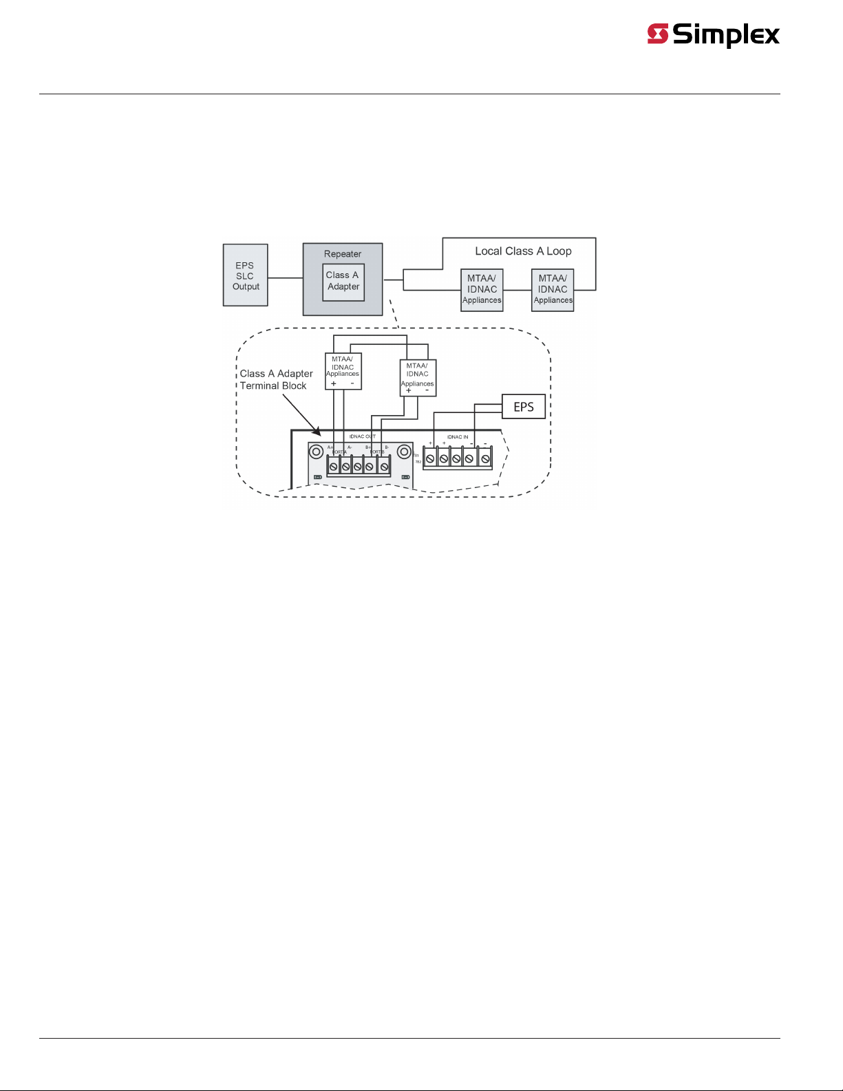
Note: In a Class A extension wiring configuration, the maximum
loop current is limited to 3A max. In this configuration, the
repeater extends the wiring distance but does not increase the
current available for the devices.
• Maximum cable load is 10,000 feet (3,048 m) per channel.
Maximum wire length from the Class A Adapter to any device is
4,000 feet (762 m).
• The nominal voltage rating is 29 VDC.
• Follow the IDNAC Speaker Wiring Application Guidelines in
579-1015 EPS Installation Instructions for TrueAlert ES speaker
and S/V appliances.
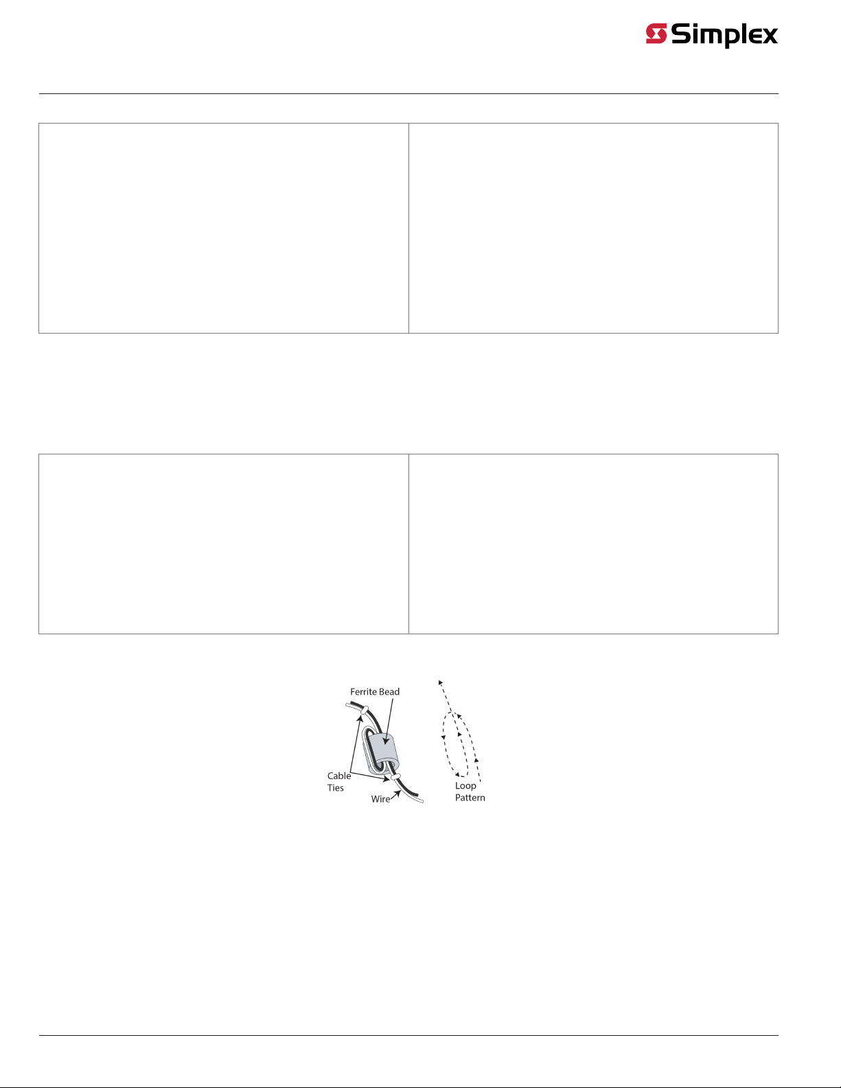
Ferrite Beads
A ferrite bead must be installed on the IDNAC input wiring, and the IDNAC output wiring. To install the ferrite bead:
Figure 5: Ferrite bead installation
1. Loop the wire though the ferrite bead close to the Repeater field wiring terminals for lowest radiated emissions (before the wires leave the box).
Do not loop the ground wire on the AC wiring through the ferrite bead.
2. Secure the ferrite bead with the provided cable ties.
page 4 579-1080 Rev. F
4009-9814 Class A Adapter Card for the 4009 IDNAC Repeater Installation Guide