Simrad PRO Argus X-Band User manual

RADAR SOLUTIONS

2The Simrad
Radar Range
Based on years of experience and designed by some of the world’s leading marine radar
system engineers, the Simrad Argus X-Band, Argus S-Band and Broadband Radar Systems
offer world class solutions for professional vessels. As the only manufacturer to offer this full
range of radar solutions, we can design a target detection solution specifically for your vessel.
Both Argus X-Band and S-Band options are fully IMO compliant and their configuration is
characterised by reduced weight, small dimensions, and compact electronics thereby offering
a great solution for a wide variety of vessels (including high speed craft).
Argus X-Band
The Argus X-Band is a state of the art professional X-band
radar including and foot antenna options* and up-mast transceiver
in both kW and kW. Thanks to the modular design, they can either be
assembled to form a stand-alone display cabinet, or be flush mounted as part of
an integrated bridge. The standard configuration always includes full ARPA, AIS and
an integrated gyro interface with Stepper, Syncro and NMEA capability as standard. An
electronic built-in interswitch for dual radar installations is also included as standard.
*Note: a ft antenna option is available and this requires a modified up-mast transceiver.
Argus S-Band
The Simrad Argus family has been expanded with the
addition of the lightest S-Band radar available in the market today. The S-Band radar has a
new slim profile antenna to reduce disturbances caused by sea waves and wind resistance.
The Argus S-Band radar does not require a separate power supply and uses the exact same
single cable as the Argus X-Band. This makes installation and service significantly easier than
most other S-Band installations in the market today.
The kW Argus S-Band Radar has enhanced near target detection, pre-wired plug and play installation, and full integration with the current Argus
X-Band Radar. The Argus S-Band is perfect for vessels over gross tonnes who require and S-Band radar ( GHz) as part of their carriage requirements.
The Argus S-Band shares some of the same proven technology and electronic components as the Argus X-Band thus reducing the required on-
board spare parts and assuring their availability via our world-wide Advantage Service program.
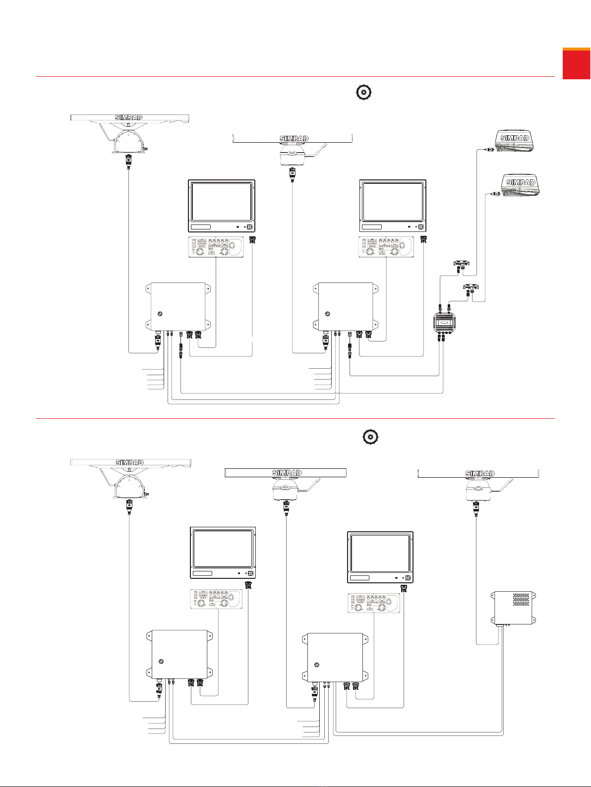
uCombined intelligent video of two radar transceivers onto
one PPI or two independent PPI on a wide screen monitor
for better situational awareness and performance
uModular and solid state construction for ease of
maintenance and servicing
uSeparate processor, monitor and operation panel offering
flexible mounting options
uUp to 100 target (ARPA) and 300 AIS targets
uFive different monitor sizes/options to suit your needs
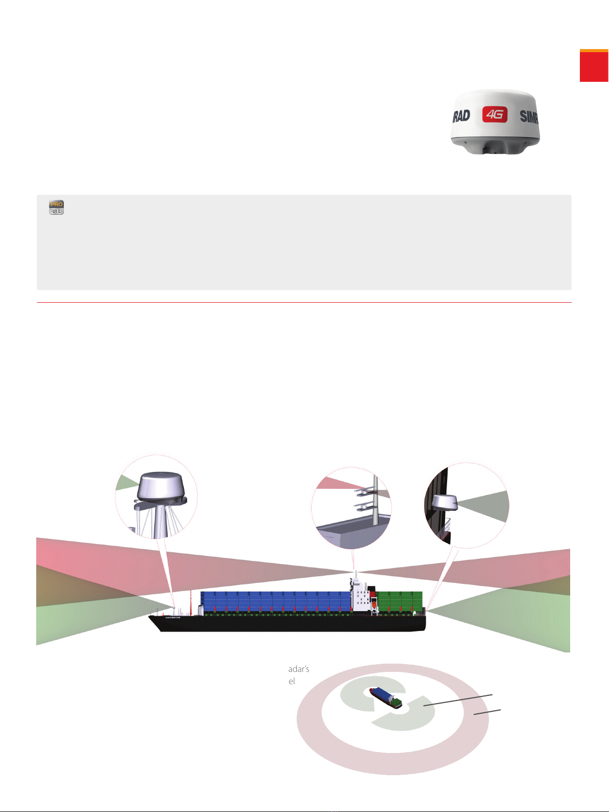
uSeamless use of up to four antennas combining X and S
Band interswitching capability. Very light S-Band antenna
that does not require a separate power supply.
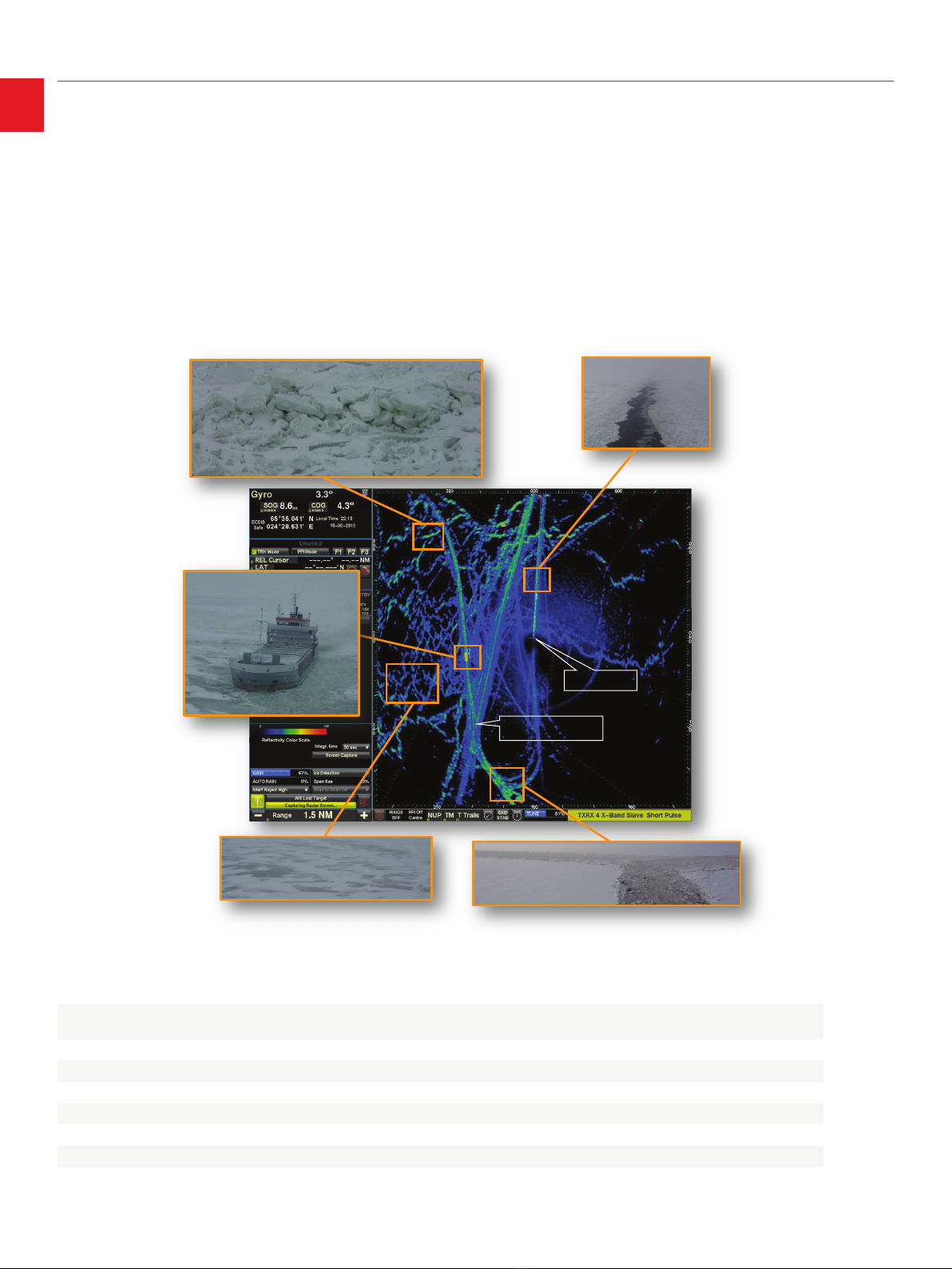
uOptional special application add-ons: Oil Spill Detection,
Small Target Detection and Ice Navigation.
uControllable antenna rotation speed 20 or 40 rpm (not
available with 12ft X-Band antenna)
uIMO approved
uPre-set video processing modes for easy operation, including
Harbour, Short Range, Medium Range, Rough Sea and Ice
uIncludes a comprehensive standard configuration with no
hidden costs. Performance Monitor, Gyro Interface, AIS, ARPA
are all included as standard.
uIntegrated FMCW Radar compatibility
KEY FEATURES

3
ARGUS Radar Display
The ARGUS display is available in three different configurations.
Argus Radar Approvals
Both the Argus X-Band and S-Band radars meet and even exceed IMO
regulations and Solas V minimum carriage requirements as follows:
. All ships of gross tonnage and upwards and passenger ships,
irrespective of size, shall be fitted with a GHz X-band Radar.
. All ships of gross tonnage and upwards shall have an automatic
tracking aid.
. All ships of gross tonnage and upwards shall have a GHz
S-band radar or where considered appropriate by the administration a
second GHz X-band radar, functionally independent of those referred
to in point .
Size of ship/craft 500 gt to 10000 gt
and HSC<10000 gt
All ships/craft
≥10000 gt
Simrad Argus
X-Band and S-Band
CATEGORIES OF SHIPS CAT 2
CAT 2H
CAT 1
CAT 1H
CAT 1 CAT 1H
CAT 2 CAT 2H
Auto-acquisition of targets NO YES YES
Minimum acquired radar
target capacity
30 40 100
Minimum activated AIS targets 30 40 300
Minimum sleeping AIS target
capacity
150 200 300
OTHER RADAR APPROVALS
- EC Marine Equipment Directive (MED)
- United States Coast Guard (USGC)
- China Classification Society (CCS)
- Russian Maritime Register of Shipping (RS)
(approval pending)
- FCC / IC
- ISO 9001
19” display
Part no. 000-10632-001
23” display
Part no. 000-10633-001
26” display
Part no. 000-11570-001
19” MO19-P Wide Screen
Part no. TBA
16” MO16-P Wide Screen
Part no. TBA
24” MO24-P Wide Screen
Part no. TBA
The table top conguration where the
monitor and keyboard are housed into
an ergonomic desktop console while
the ARPA electronics are contained in a
separate bulkhead mounted cabinet.
The deck conguration provides an
optional display deck stand which can
also house the electronic cabinet. Two
different options available :
• Desk-Top Cabinet for 26“ with Pedestal
• Desk-Top Cabinet for 23“ / Adapter
Frame kit for 19” Monitor / Pedestal
The modular conguration with
monitor, keyboard and Electronic Core
Unit supplied as three separate
modules which can be flush mounted
into the bridge console to the
customers´ preference.
ARGUS keyboard
Part no. TBA
An external mouse can be used in
conjunction with the Argus keyboard.
ARGUS Core Unit
Part no. 000-10330-001
Non-IMO Argus Core unit
for special applications
Part no. 000-10883-0001

4ARGUS Radar Screen Presentation
ARGUS Special Applications
We are among the first companies in the world to provide special application add-ons that
work in parallel with an IMO/SOLAS ARPA navigational radar (note a dedicated core unit must
be available for full IMO approval for navigational radar). From the ships owners’ point of view,
the most important benefit is the reduced maintenance costs in terms of installation, service
and spare parts, and the officer on watch only has to learn to use one radar system.
There are three additional special application software packages available offering Oil Spill
Detection, Small Target Detection, and Ice Navigation.
• Square Radar PPI - same as a chart on an ECDIS.
• Simplied PPI presentation - choose from centered or
offset PPI to allow for flexible presentation options.
• Main radar operator settings - one line containing most
used radar functions and information.
• User selectable viewing area
19” and 23” displays radar presentation:
• Square or wide Radar PPI to see more
• Simplied PPI presentation - choose from centered or offset
PPI to allow for flexible presentation options.
• User selectable second PPI - use for dual range, extra target
zoom, Broadband Radar Integration, or for center presentation.
• User selectable viewing area - select CCTV, full Conning or
second radar scanner (including Broadband 4G), all without
compromising IMO performance requirements.
Wide screen (26”) radar presentation:
High performance
radar showing crisp
and clear detail.
Wide screen - add up to 3 cameras per monitorSquare radar PPI to see more
One line containing the most used
radar functions and information.
Key navigation data
Ability to display radar
image from another
antenna (including
Broadband), or a
zoomed image from
the primary antenna.

ARGUS Special Applications
5
ARGUS Special Applications
Vessels towing oil recovery
booms into place
Vessel spilling oil
Spot area of oil
concentration
Oil spot area =
10.38km2
Oil volume =
326,592 barrels
Oil thickness
set to 5mm
1. OIL SPILL DETECTION
Early detection and the ability to mount an emergency response are essential should an oil spill occur. Adding the Oil Spill Detection capabilities
to your Simrad Argus X-Band or S-Band Radar is a must to stay operational. An Argus OSD Radar will increase your hours of operation and
efficiency, as the vessel can now work in the dark and know which part of the oil slick to concentrate on.
The Simrad Argus Oil Spill Detection application works by receiving and processing signals in real-time from on-board transceivers. The water
surface is usually dampened when it is contaminated by oil, so the backscatter of microwave radiation from these waves is unlike the rest of the
sea. The radar is then able to highlight the dampening of the reflected microwave radiation on the radar display, thus calculating the size, position
and drift (speed and course) of the oil spill. We let you see inside the oil spill!
The Simrad Argus Radar with Oil Spill Detection software has been successfully tested during two NOFO (Norwegian Clean Seas Association for
Operating Companies) on-water exercises. The radar has been found suitable for use in NOFO mode of operation. The success of this application is
further supported by the dozens of installations that are in operation today around the world.
2. SMALL TARGET DETECTION
Being able to identify small targets can be a matter of life and death. The Simrad Argus Small Target Detection unlock key allows the user to access
a set of radar functions specific to identifying small targets amongst the sea clutter.
The superior detection of small objects in clutter is carried out by using advanced signal averaging to suppress the chaotic sea clutter returns
in the background, and preserve the signal level of stationary targets. Therefore, in terms of amplitude of the received radar signal, the distance
between the clutter and target is increased and the target detect-ability is enhanced.
In addition, the operator can manually adjust the colour palette threshold to suit sea and weather conditions by adjusting some parts of the radar
signal from grey to green to highlight the presence of small targets above the average sea clutter.

63. ICE NAVIGATION
For vessels operating in low temperature environments, purchasing the Ice Navigation unlock key helps reduce any potential risk of serious
incidents in Arctic waters. This special application supports both strategic route planning and tactical ice avoidance.
The reflectivity properties of different objects (or surfaces) will be displayed on screen as different colours. Sea water, grease ice, first-year ice and
in general low radar reflectivity areas are represented with a shade of colour from black through to green, while land, old hard ice, vessels etc. are
represented by a shade of colour from green through to red.
The Ice Navigation unlock key will assist the ships navigators to set a course that will follow safety routes for significant time savings and to
avoid damage to the ship, ultimately increasing operational profits. The Ice Navigation software has been tested and approved by the Russian
administration for cold weather operation down to -50C.
Argus Radar Special Application Conguration Options:
PART NUMBER CONFIGURATION OIL DETECTION ICE NAVIGATION SMALL TARGET
DETECTION
305172A2 USB Unlock Key for Oil/Ice/Small Target detection software ✔ ✔ ✔
305172A3 USB Unlock Key for Oil Spill detection software ✔
305172A4 USB Unlock Key for Ice Navigation software ✔
305172A5 USB Unlock Key for Small Target detection software ✔
305172A6 USB Unlock Key for Oil/Ice Navigation software ✔ ✔
305172A7 USB Unlock Key for Oil/Small Target detection software ✔ ✔
305172A8 USB Unlock Key for Ice/Small Target detection software ✔ ✔
Own-Ship
Icebreaker route

BROADBAND RADAR OVERVIEW
7
• Docking Radar capabilities -with the optional Broadband Radar’s
close range performance, the navigator or pilot can monitor the vessel
relative to the dock or other structure (such as a wind farm turbine)
right up to the point of contact. Total flexibility of installation is
available due to zero radiation hazard enabling a scanner location
that is not possible with pulse radars’inherent radiation.
BROADBAND AND ARGUS RADAR INTEGRATION
Integrating Broadband Radar with the Argus X or S-Band Radars is now a standard feature. Simrad Argus X-Band and S-Band Radars can combine
signals from up to four transceivers with different output power, frequency band, antenna sizes and mounting positions.
Utilizing solid-state technology, the breakthrough 4G™ Broadband Radar solution provides superior target detection and separation, ease of
operation, and a new level of navigational safety to a wide range of applications.
Integrate the Simrad Broadband 4G™ Radar with an Argus X or S-Band for complete close range coverage.
• Tighten blind zones and reduce piracy threats –targets can be detected within a 5m range ensuring all potential threats are monitored.
Broadband Radar
X-Band/S-Band
Radar
Simrad has introduced a revolutionary radar system unlike anything else on the navigation market. Utilising
broadband Frequency Modulated Continuous Wave (FMCW), this breakthrough technology provides superior
target detection and separation, ease of operation and a new level of navigational safety. Broadband Radar
near-range performance and usability is optimized with the addition of high-speed antenna rotation (48 RPM).
This Broadband 4G™ Radar has all of the benefits of our revolutionary Broadband 3G™ Radar but with more
advanced features, including beam sharpening for target separation control, dual range radar and increased
target detection capabilities. The Broadband 4G™ also includes 18 range scales all the way down to a 50m scale,
providing the operator unprecedented short range performance.
uBeam sharpening with target separation control
uDual range anywhere from 5m to 36NM
uUp to 48RPM at less than 1NM
uDirectional STC and Sidelobe suppression
uFMCW technology with inherent LPI
uExtremely low emissions
uInstantOn™
KEY FEATURES
Broadband Radar Broadband Radar
X-Band Radar X-Band Radar
BROADBAND RADAR OVERVIEW

8System Congurations
1. IMO APPROVED X OR SBAND SYSTEM
2. IMO APPROVED X AND SBAND INTERSWITCHED
ARGUS X-Band
ARGUS S-Band
26” Wide Display 26” Wide Display
ARGUS CoreARGUS Core
15m, 30m, 60m
Radar Interface Cable
15m, 30m, 60m
Radar Interface Cable
DVI VideoDVI Video
To Heading DeviceTo Heading Device
Interswitch 1-2
Interswitch 2-1
To LOGTo LOG To EPFSTo EPFS To AISTo AIS
ARGUS X-Band ARGUS S-Band
26” Wide Display
26” Wide Display
ARGUS Core
ARGUS Core
DVI Video DVI Video
To Heading Device
To Heading Device
To LOG
To LOG
To EPFS
To EPFS
To AIS
To AIS

System Congurations
9
DVI
Video
NEP-2
System Congurations
To Heading Device
To Heading Device
To Heading Device
To Heading Device
Interswitch 1-2
Interswitch 1-2
Interswitch 2-1
Interswitch 2-1
To LOG
To LOG
To LOG
To LOG
To EPFS
To EPFS
To EPFS
To EPFS
To AIS
To AIS
To AIS
To AIS
To VDR To VDR
3. IMO APPROVED WITH BROADBAND RADAR INTEGRATION
4. LONG CABLE RUN INSTALLATION SHOWING X AND SBAND
ARGUS X-Band
ARGUS S-Band
Broadband
4G™ Radar
Broadband
4G™ Radar
ARGUS X-BandARGUS X-Band
ARGUS S-Band
SRT Adaptor
26” Wide
Display
26” Wide
Display
26” Wide Display26” Wide Display
ARGUS CoreARGUS Core
15m, 30m, 60m
Radar Interface Cable
15m, 30m, 60m
Radar Interface Cable
15m, 30m, 60m
Radar Interface Cable
Cable length: up to 300m
15m, 30m, 60m
Radar Interface Cable
15m, 30m, 60m
Radar Interface Cable
DVI VideoDVI Video
DVI VideoDVI Video

10
364 mm
200 mm
Grounding Bolt
Installation Connector
Antenna xing bolts
(threaded bolds 4xM8
tighten to 22Nm)
ANTENNA LENGTH / SWING CIRCLE (6ft 1800 mm - 9ft 2650 mm)
804 mm
534 mm
200 mm
Forward
696 mm
466 mm
90.00˚
Optional output cables
(revolve cables 90°)
768 mm
125º
306 mm
74 mm
260 mm
128 mm
510 mm
FRONT VIEW
19" and 23" Monitor 19", 23" and 26” Monitor
19", 23" and 26” Monitor
26" Monitor
635 mm
754 mm
680 mm
340 mm
13 mm
750mm
1150mm
125º
SIDE VIEW
584 mm 2
0
3623 mm (Swing circle 3695 mm)
654 mm26 mm 52.5 mm
499 mm
365.5 mm 133.5 mm
765 mm
394 mm
478 mm
Antenna xing nuts
(threaded nuts M8
tighten to 20Nm)
Safety switch
cable entrance
(optional)
Grounding bolt
System
connector
Dimension Drawings
ARGUS XBAND RADAR UPMAST
ARGUS SBAND RADAR UPMAST
ARGUS RADAR 19", 23" AND 26" MOUNTING

Dimension Drawings
11
Dimension Drawings
460 mm
250 mm (1)
(1) Minimum distance to the oor
(2) Minimum distance to the wall and to others equipments
SIDE VIEWFRONT VIEW FRONT VIEW
15 mm
85 mm (2)
15 mm
260 mm 45 mm
400 mm
150 mm
FRONT VIEW
FRONT VIEW
FRONT VIEW
SIDE VIEW
483 mm
465 mm
444 mm
98.75 mm
267 mm
14 mm68 mm
434 mm
BOTTOM VIEW
TOP VIEW
16 mm
412 mm
584 mm
568 mm
126 mm 281 mm
534 mm
619 mm8 mm
ø 6.5 mm
(4x)
8 mm 15 mm
102 mm
20 mm
20 mm 459 mm
499 mm
313 mm108.5 mm
20 mm595 mm
635 mm
ø 6.50 mm THRU
BOTTOM VIEW
14 mm
85 mm
TOP VIEW
540 mm
71 mm
22.05 mm
489.90 mm
SIDE VIEW
BOTTOM VIEW
SIDE VIEW
10.5 mm 231 mm 231 mm 10.5 mm
483 mm
7 mm 166 mm 7 mm
180 mm
ARGUS CORE UNIT ARGUS RADAR KEYBOARD
ARGUS RADAR 19” MONITOR
ARGUS RADAR 23” MONITOR
ARGUS RADAR 26” MONITOR

FRONT VIEW
FRONT VIEW
FRONT VIEW
SIDE VIEW
SIDE VIEW
SIDE VIEW
BOTTOM VIEW
BOTTOM VIEW
BOTTOM VIEW
SIDE VIEWFRONT VIEW
BOTTOM VIEW
280 mm
489.6 mm 489.6 mm
488.6 mm
488.6 mm
400mm
260mm
383mm
MAX 25.4 mm
8 mm 66.0 mm
MAX 88.0 mm
233mm
478mm
305mm
MAX 25.4 mm
8 mm
8 mm
461mm
278mm
625mm
386mm
MAX 25.4 mm
598mm
349mm
66.0 mm
MAX 88.0 mm
66.0 mm
MAX 88.0 mm
12
4G™ BROADBAND RADAR
16” MO16P WIDE SCREEN
19” MO19P WIDE SCREEN
24” MO24P WIDE SCREEN

Technical Specications
13
Technical Specications
DISPLAYS
Monitor - size and
resolution
19” LCD - 1280x1024
23” LCD - 1600x1200
26” LCD Wide screen - 1920x1200
16” MO16-P Wide Screen 1366x768
19” MO19-P Wide Screen 1366x768
24” MO24-P Wide Screen 1920x1080
Radar picture >180 mm (approval pending) / >250 mm / >320 mm
Presentation Modes Day/Night modes
Relative motion (RM) Head, Course and North Up
True Motion (TM) Course and North Up
Off-centering Up to 50% of range scales in use
Range Scales 0.125; 0.5; 0.75; 1.5; 3; 6; 12; 24; 48; 96 nm
Range Resolution 3 m on 0.75 nm range scale
Azimuth resolution 0.1°
Trackball Polar and Geographical coordinates. Continuously displayed
Diagnostic On-line diagnostic programs
TARGET TRACKING FACILITIES
Acquisition Manual or automatic up to 100 targets
Tracking Automatic up to 100 targets
Auto acquisition /
Guard Zones
One auto acquisition zone stabilized on Ownship heading and
size/shape configurable. Four sectors with fixed width of 0.5
nm configurable as auto acquisition or guard zone
AIS FACILITIES
Presentation Up to 300 targets chosen as the nearest to own ship
AIS overflow mechanism of priority
Safe checking All 300 targets in sleep or activated stated
Auto acquisition /
Guard Zones
Same zones as described for Target Tracking facilities. The
System provides up to four Guard Zones
TRIAL MANOEUVERS
Trial course
ForTarget Tracking and AIS target. Manually adjustable from 0°
to 360° or automatically computed within135° with reference to
present course.
Trial speed Adjustable from 0 to 50 knots
Trial ROT Adjustable from 1° to 60°/min
Trial time Adjustable with 1 min increments
MAPPING
Operator compiled maps up to 120 segments plus symbols and text strings with
selectable colors and line styles.
Map stabilization Relative, true (Dead Reckoning) or geographic
Map storage By name, on a built-in non-volatile memory. Transferable via
USB Memory stick
Map adjustment Position and Orientation
Parallel index Four independent parallel index lines
Data readout Own ship data ARPA target data
AIS target data
System setting Safe minimum CPA and TCPA, vector / past position / trial /
trials time
OTHERS
Alarms
Acoustic and visual warning for: Dangerous Target, Target
in Guard Zone, Lost Target, System Failure and external
interface sensors (EPFS and AIS).
Other features Anchor watch, echo reference speed (not for AIS enabled
systems), EPFS speed.
Inputs Serial interface NMEA0183 (IEC 61162-1/2)Gyro, Speed log,
EPFS, AIS, Wind sensor, Ext. Alarm Interface
Outputs
Serial interface NMEA 0183 (IEC 61162-1/2) RATTM-RAOSD-
RARSD-RAALR sentence AIACK for AIS alarm acknowledge,
RATTD, RATLB, Dead Man Alarm, Power Fail, Danger Target,
Video output for VDR
Gyro interfaces
Synchro:
. Voltage value: 50 ÷ 115 Vac +/- 10% (reference)
. 50/60 Hz or 300/400 Hz
. Gear ratio: 1:360, 1:180, 1: 90, 1:36
Stepper:
. Voltage value: 15 to +100 V positive (Vef ) -15 to -100 V
negative ( Vef )
. Gear ratio: 1:360, 1:180, 1: 90, 1:36
Stepper rectified:
. Voltage value: 100 Vac (Vef )
. Frequency: 50/60 Hz or 300/400 Hz ±6%
. Gear ratio: 1:360, 1:180, 1: 90, 1:36
Serial:
. RS422 standard FNMEA or RS232
. Load: ≥ 7 KΩ, terminated 120 Ω
Other interface Dual Ethernet 10/100Mbit/s USB 2.0 port
ENVIRONMENTAL CONDITIONS
Operating temperature
Display Unit: -15° to 55°C (IEC 60945 protected equipment)
Antenna group: In-door -15° to 55°C
Out-door, std -25°C to 55°C
Out-door option: Down to -40°C (Pedestal with heater)
Storage Temperatures 25°C to 70°C (IEC 60945)
Relative humidity Up to 93% at 40°C (IEC 60945)
IP class IP41 (display)
Vibrations As per IEC 60945
Power supply
Display Unit: 220/115 VAC 50/60 Hz (30 W)
SRT X-Band Radar: 220/115 VAC 50/60 Hz (300 VA)
Fed by Core unit
Power consumption 500 W max (depending on monitor and wind load)
Type testing in
accordance with
IMO-Resolution A.278 (VIII), A.694 (17), A.823 (19), MSC 191
(79), MSC 192 (79)
EN 62388 Ed.1.0, 2008
EN 62288 Ed.1.0, 2008
EN 60945 Ed.4.0, 2002 incl. Corr.1, 2008
EN 61162-1 Ed.4.0, 2010
EN 61162-2 Ed.1.0, 1999
XBAND RADAR UPMAST
Peak Power (kW) 12 or 25
Pulse length (nsec) 60 – 250 - 800
PRF (Hz) 3000-1500-750
Antenna model 6X 9X 12X
Gain (dB) 29 31 32.5
Horizontal beam width
at -3 dB (°) 1.3 0.9 0.7
Vertical beam width at
-3 dB (°) 22 22 22
Weight of Antenna
incl. Pedestal with
Transceiver (kg)
40 44 49
Nominal Rotation speed
(RPM) 22 or 40 22 or 40 22
SBAND RADAR UPMAST
Peak Power 30
Pulse length (nsec) 60 – 250 - 800
PRF (Hz) 3000 - 1500 - 750
Antenna model 12S/LP
Gain (dB) 27
Horizontal beam width at -3 dB (°) 1.9
Vertical beam width at -3 dB (°) 24
Weight of Antenna incl. Pedestal with Transceiver
(kg) 125
Nominal Rotation speed (RPM) 20
GRAPHIC FUNCTIONS
True or relative time adjustable vectors
Target identification number, track-ball marker and true marks
AIS identification number, ship names or call signs
Time adjustable past position plots
Four independent parallel index lines
Waypoints and Route from Electronic Position Fixing Systems
Own ship shape and activated AIS target shape on lower range scales
ARGUS SPECIFICATIONS

14
GENERAL
Compliance FCC/IC/R&TTE
FCC ID: RAY3G4G
IC ID: 4697A-3G4G
Human Exposure General Public Safety Limit
– touch dome anywhere.
Environmental IEC60945 4th edition 2002-2008
Operating Temperature: -25º to +55ºC
Relative humidity: +35ºC, 95% RH
Waterproof: IPx6
Relative wind velocity 51 m/sec (Max:100 Knots)
Power consumption Operating: 18W (Typ.) @ 13.8VDC
Standby: 2W (Typ.) @ 13.8VDC ~ 150ma
DC input (at end of radar cable) 9V to 31.2Vdc (12/24 Volt systems).
Reverse polarity protection
Transmitter Source (pre-heating
time ) No magnetron – Instant On™
Outside dimensions Height 280mm x Diameter 488mm
Weight (no cable) 7.4 kg
RADAR AND ANTENNA PARAMETERS
Radar Ranges 200’ to 24nm with 17 range settings (nm/
sm/km)
Rotation 24/36 rpm +/- 10%; Mode Dependant
Transmitter frequency X-band - 9.3 to 9.4Ghz
Transmitter source (warm-up time) No Magnetron – all solid state. Instant On™
Plane of polarization Horizontal Polarization
Transmitter peak power output (at
antenna port) 165mW (nominal)
Main Bang Dead Zone & Tuning None – not a pulse radar
Sea and Rain Clutter 5X less than a pulse radar
Sweep Repetition Frequency 200Hz
Sweep Time 1ms
Sweep Bandwidth 75MHz max
Horizontal Beam width (Tx and Rx
antenna) 5.2º+/-10% (-3dB width)
Vertical Beam width (Tx and Rx
antenna) 25º+/-20% (-3dB width)
Side lobe level (Tx and Rx antenna) Below -18dB (within ±10¡);Below -24dB
(outside ±10¡)
Noise figure Less than 6dB
COMMS/CABLING/MOUNTING
Communication Protocol High Speed Ethernet and Serial
Heading NMEA2000/Simnet (with RI-10 interface box)
Inter Connecting cable length 20m standard with RJ45 thin custom
connector – Display model dependent
Maximum inter-connecting cable
length 100m
Bolts (4) M8x30 - 304 stainless steel
Footprint W233mm (port/starboard) x L141.5mm
Part Number Description
000-10421-001 4G Broadband Radar including 20m (66 ft) scanner
cable, RI10 interface box, 1.8m (6 ft) yellow Ethernet
cable
000-10496-001 Argus 12U/6X P HSC System - includes 12kW Upmast
Scanner with 6’ Antenna, Control Panel and Core Unit
000-10497-001 Argus 12U/6X P System - includes 12kW Upmast Scanner
with 6’ Antenna, Control Panel and Core Unit
000-10498-001 Argus 12U/9X P HSC System - includes 12kW Upmast
Scanner with 9’ Antenna, Control Panel and Core Unit
000-10499-001 Argus 12U/9X P System - includes 12kW Upmast Scanner
with 9’ Antenna, Control Panel and Core Unit
Part Number Description
000-10500-001 Argus 25U/6X P HSC System - includes 25kW Upmast
Scanner with 6’ Antenna, Control Panel and Core Unit
000-10501-001 Argus 25U/6X P System - includes 25kW Upmast Scanner
with 6’ Antenna, Control Panel and Core Unit
000-10502-001 Argus 25U/9X P HSC System - includes 25kW Upmast
Scanner with 9’ Antenna, Control Panel and Core Unit
000-10503-001 Argus 25U/9X P System - includes 25kW Upmast Scanner
with 9’ Antenna, Control Panel and Core Unit
000-11753-001 Argus 30U/12S (S-Band) System - includes 30kW upmast
transceiver with 12’ Antenna, Control Panel and Core Unit
BROADBAND RADAR SPECIFICATIONS
ARGUS RADAR SYSTEMS PART NUMBERS

Technical Specications
15
A DVA N TAG E :
SERVICE BEYOND
THE STANDARD.
A DVA N TAG E :
SERVICE BEYOND
THE STANDARD.
uBy choosing a product from the Simrad Professional
Series, you automatically qualify for standard
warranty support, which oers two years of
protection on products which fail to meet the
high manufacturing standards, and true on board
support for qualifying products.*
uAs well as these standard warranty features, we have now
expanded our service offerings with the Advantage Program.
This is free to join and available to all Simrad Professional
Series customers. The Pro Series Advantage Service program
offers the most comprehensive levels of service available in
the marine electronics industry today.
*Subject to published warranty terms and conditions, available on PRO.SIMRAD-YACHTING.COM
CERTIFIED DEALER ADVANTAGE
A network of qualied Master Distributors
and Certied Dealers in more than
countries, ready to provide spare parts
and onboard support to ensure prompt
and ecient service. Supported by fteen
regional Navico hubs, co-ordinating
seamless support and communication
across the globe.
7-YEAR ADVANTAGE
The -Year Advantage oers comprehensive
support for years, including upgrade
options to current technology products, an
online spare parts locator and price list.
ONBOARD ADVANTAGE
The OnBoard Advantage Program provides
customers with the option to receive
warranty service by a Certied Dealer
onboard their vessel for the rst years.
FASTFIX ADVANTAGE
FastFix Advantage ensures that if a
qualifying product is identied as defective,
customers will be shipped a replacement
product or spare part within business day.
EXTENDED WARRANTY ADVANTAGE
Extended Warranty Advantage oers
exible extended warranty options for
Simrad Professional Series systems.
SYSTEM BUILDER ADVANTAGE
AVAILABLE The System Builder
Advantage oers Simrad Professional Series
Dealers an Apple iPad tool that combines
a current price book with a product
information guide and more in an easy-to-
use shopping cart- style purchase format.
24/7 ADVANTAGE
Support for Simrad Professional Series
customers hours a day, days a week.
CUSTOMER PORTAL ADVANTAGE
Customer Portal Advantage oers Certied
Dealers access to online tools and technical
information via a new BB portal.
VESSEL PORTAL ADVANTAGE
Vessel Portal Advantage oers Certied
Dealers access to extensive detail for
Certied Vessels via an online portal.
TRAINING ADVANTAGE
Training Advantage supports Dealers with
technical training courses for sales sta,
engineers and technicians. Comprehensive
and up to date knowledge of the complete
product range enables Dealers to provide
world-class service.

16
OUR HERITAGE: ESTABLISHED IN 1947.
With more than 60 years of maritime expertise invested in delivering solutions to the
professional market, we have unique knowledge to support professional customers
with cost effective navigation solutions.
Contact us:
Navico Asia Pacic: Tel: +64 9 925 4500 Email: ps.apac@navico.com
98510362003
This manual suits for next models
1
Table of contents
Other Simrad Marine Radar manuals