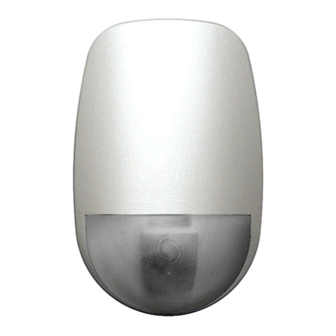
Simtronics MultiTox DGi-TT7-E User manual

Operating Manual
NOSP 16452-05 (03/2018)
MultiTox Detector
MultiTox DGi-TT7-E
DGi-TT7-O
DG-TT7-S

MultiTox : DGi-TT7-E/O & DG-TT7-S Pa e 2 / 60 NOSP 16452-05 (08/2016)

MultiTox : DGi-TT7-E/O & DG-TT7-S Pa e 3 / 60 NOSP 16452-05 (08/2016)
Note
This manual must be carefully read by those who are or will be responsible for the operation
or maintenance of this product. The product may not perform as desi ned if not used or
maintained in accordance with the manufacturer's instructions.
The warranty made by Simtronics with respect to the product is voided if the product is not
used and maintained as described in this manual.
Please read the eneral warnin s in chapter 9.
© Simtronics SAS, all ri hts reserved.

MultiTox : DGi-TT7-E/O & DG-TT7-S Pa e 4 / 60 NOSP 16452-05 (08/2016)
1. Product description ............................................................................................................. 6
1.1. Application ................................................................................................................... 6
1.2. DGi-TT7-E .................................................................................................................... 7
1.3. DGi-TT7-O .................................................................................................................... 7
1.4. DG-TT7-S ..................................................................................................................... 7
1.5. Heatin ......................................................................................................................... 7
1.6. Technical specifications .............................................................................................. 8
1.7. Detection cartrid e ...................................................................................................... 9
1.8. Wireless Confi uration Tool ........................................................................................ 9
1.9. Product Code ............................................................................................................. 10
2. Techical features............................................................................................................... 12
3. Scales and technical data ................................................................................................. 16
4. Installation ........................................................................................................................ 17
4.1. Positionin ................................................................................................................. 17
4.2. Assembly ................................................................................................................... 17
4.3. Electric Connection.................................................................................................... 20
4.4. Detection cartrid e .................................................................................................... 26
5. Commissionin ................................................................................................................. 27
5.1. Visual inspection ........................................................................................................ 27
5.2. Power-up ................................................................................................................... 27
5.3. Operational tests ....................................................................................................... 27
6. Operation ........................................................................................................................... 28
6.1. Environmental conditions .......................................................................................... 28
6.2. Inhibition .................................................................................................................... 29
6.3. Si nal current loop .................................................................................................... 29
6.4. Alarm indication......................................................................................................... 30
6.5. Display indication ....................................................................................................... 31
6.6. Wireless communication tool TLU600 ....................................................................... 32
6.7. Information menu [INFO] ........................................................................................... 35
6.8. Adjustment menu [ADJT] ........................................................................................... 36
6.9. Maintenance menu [MAIN] ........................................................................................ 41
7. HART communication ....................................................................................................... 42
8. Maintenance ...................................................................................................................... 43
8.1. Periodic maintenance ................................................................................................ 43
8.2. List of main faults ...................................................................................................... 44
8.3. Replacin the cartrid e ............................................................................................. 45
8.4. Replacin the complete detector .............................................................................. 45

MultiTox : DGi-TT7-E/O & DG-TT7-S Pa e 5 / 60 NOSP 16452-05 (08/2016)
9. Warnin s ........................................................................................................................... 46
9.1. Safety ......................................................................................................................... 46
9.2. Ownership and confidentiality ................................................................................... 46
10. Warranty ........................................................................................................................ 46
11. CERTIFICATIONS AND STANDARDS ............................................................................. 47
11.1. Product standards.................................................................................................. 47
11.2. Approvals ............................................................................................................... 47
11.3. Markin .................................................................................................................. 48
12. Accessories and spare parts ......................................................................................... 49
12.1. Accessories ............................................................................................................ 49
12.2. Spare parts ............................................................................................................. 51
12.3. Gas table codes & ran e table codes .................................................................... 52
13. Declaration of conformity .............................................................................................. 54
14. Contact details ............................................................................................................... 56

MultiTox : DGi-TT7-E/O & DG-TT7-S Pa e 6 / 60 NOSP 16452-05 (08/2016)
1. PRODUCT DESCRIPTION
The DGi-TT7-E is desi ned to monitor poisonin risk induced by the presence of toxic ases
or vapours (hydro en sulphide, carbon monoxide, ammonia...).
The DGi-TT7-O is desi ned to monitor the oxy en concentration in %vol either for inertin
(scales 1 or 5%vol.) or in breathable atmosphere control (Scale 0-25%vol).
Both versions are equipped with electrochemical cells.
The DGi-TT7-S is desi ned to monitor poisonin risk induced by the presence of toxic ases
or vapours, such as hydro en sulphide. This version is equipped with semiconductor cells.
Detectors can be connected to a lar e ran e of controllers or PLC.
These detectors may be confi ured usin the portable communication terminal (TLU600),
providin flexibility to the user.
Thus, calibration and maintenance operations can be undertaken by a sin le operator.
MultiTox are also available for use in an addressable network system with distributed
intelli ence SYNTEL. For more information, please refer to the Syntel module interface
operatin manual.
1.1. Application
The DGi-TT7 and DG-TT7 are suitable for indoor or outdoor use and offer a fast response
time. Typical applications include:
•Stora e of toxic products
•Monitorin of processes with toxic products
•Oxy en detection in inert atmosphere (DG-TT7-O)
•Chemical and petrochemical plants
•Drillin platforms
•Refineries

MultiTox : DGi-TT7-E/O & DG-TT7-S Pa e 7 / 60 NOSP 16452-05 (08/2016)
1. . DGi-TT7-E
The DGi-TT7-E is a MultiTox detector based on a transducer with electrochemical cell, which
requires oxy en to function properly.
The measurin principle is based on a redox reaction.
In the event of a lon period without oxy en, the measurement will not be representative of
ases or vapours concentration.
The characteristics of the device can also be altered by exposures to hi h concentrations or
by extended periods in hot and dry atmosphere.
1.3. DGi-TT7-O
The DGi-TT7-O is a MultiTox detector based on a transducer with electrochemical cell. The
measurement ran e is expressed in %vol O2.
The measurin principle is based on one of the principle of the « oxy en cell ».
Characteristics of the device can also be altered by exposures to extended periods in hot and
dry atmosphere.
1.4. DG-TT7-S
Le DG-TT7-S is a MultiTox detector based on a transducer with semi-conductor cells, which
requires oxy en to function properly. It is used mainly for hydro en sulphide detection in
difficult industrial environment.
The measurin principle is based on oxidation and adsorbin reactions on films surface of
heated semi-conductor.
This sensor uses a sensitive element that only requires half-yearly calibration and does not
require any injection of hi h concentration as to reactivate his sensitive element.
The measurement will not be representative anymore of the concentration of ases or
vapours if the detector is exposed too lon time without oxy en or in a very dry atmosphere.
Characteristics of the device can also be altered by the presence of some poisons, such as
silicon vapours.
1.5. Heating
In hard environmental conditions, with condensation or frost, ases and vapours may not
reach the sensor. The device takes into account this difficulty and keeps its temperature
sli htly above that of the ambient atmosphere.

MultiTox : DGi-TT7-E/O & DG-TT7-S Pa e 8 / 60 NOSP 16452-05 (08/2016)
1.6. Technical specifications
Each detector is constructed as follows:
•A wall-mounted support secured by three screws and includin cable land (M20)
(optional). There are 2 standard entries and an optional one.
•A stainless steel explosion-proof housin containin :
•A set of tropicalized electronic cards
•A display and infrared communication electronic card. Allowin the
communication with the remote control (TLU600)
•A colour coded cartrid e with a label located in the lower part of the detector, a reen
one for the toxic as detectors with electrochemical cell (DGi-TT7-E), a blue one for
the oxy en deficiency as detectors with electrochemical cell (DGi-TT7-O) and an
oran e one for semi-conductor toxic as detectors (DG-TT7-S)
The cartrid e is connected to the detector’s body by an open rin leavin
the label visible.
A colored rin enables the identification of the device type at a lar er
distance.
•A metallic support cable (optional) connects the wall mountin support and the
housin , which makes the maintenance easier.
Fi ure 1 :
Layout drawin
(Outline drawin – see Fi ure 2 : )

MultiTox : DGi-TT7-E/O & DG-TT7-S Pa e 9 / 60 NOSP 16452-05 (08/2016)
1.7. Detection cartridge
Detection cartrid es are:
•Intrinsic safety “ia” for the DGi-TT7-E- and DGi-TT7-O versions. They can be removed
when the detector is powered.
•Explosion proof “d” for the DG-TT7-S versions. They cannot be removed when the
detector is powered.
They are common to all Simtronics MultiTox products in order to reduce the number of
spares parts.
•DGi-RT7-E / DGi-RT7-O et DG-RT7-S: Network versions for Syntel loop,
•DGi-TT7-E / DGi-TT7-O et DG-TT7-S: « Telecapteur » versions,
Storin electrochemical cartrid es ( reen or blue label) for lon periods is not
recommended, as their shelf-life is short. Cartrid es should be used within 6 months (from
the date of purchase).
In order to uarantee the metrolo ical characteristics of the device, the cartrid es must be
stored in their ori inal packa in until commissionin . For a lon -term stora e, the
cartrid es will be stored in a dry place, between 0°C and 20°C.
After a lon stora e period, more than one month, the cartrid e will be stabilized for several
hours, in order to perform the nominal characteristics.
1.8. Wireless Configuration Tool
Information and status of the detector are available via the wireless confi uration tool
TLU600/610.
Confi uration and tests are performed usin this wireless confi uration tool (IrDA protocol).
This tool is common for all Simtronics MultiFlame, MultiXplo and
MultiTox products.
The TLU600/610 provides access to devices that, otherwise, would
require major lo istic operations for maintenance or for
confi uration (calibration…).
For more details, please refer to the wireless confi uration tool
operatin manual.
Some versions are equipped with the HART communication protocol, enablin
the use of all functions available with the TLU (see §7)

MultiTox : DGi-TT7-E/O & DG-TT7-S Pa e 10 / 60 NOSP 16452-05 (08/2016)
1.9. Product Code
Product codes are created from functional codes defined as below:
DGi-*T7-****-***-**-***-*-*-* et DG-*T7-****-***-**-***-*-*-*
Detector type
T T 7 31 AF -S X H -C 0 -00J -0 -C -0
C
**
Compact Sensor
T
**
Télécaptor
R
**
Network version
S
**
Replacement cell
X
**
Accessories
Families
*
T
*
Toxic
*
V
*
Flame
*
X
*
Flammable gas
*
0
*
None
Version
**
6
BT606 housing
**
7
BT10 housing
Gas type
** Refer to gas matrix
Measurement range
** Refer to gas matrix
Type
XV UVIR2
XT IR3
XW UV
Detection range
A0 Standard range
B0 Long range
Input
Type
0
**
Not used or flame
E
**
Electrochemical
S
**
Semi-conductor
K
**
Catharometer
X
**
Catalytic
M
**
MECH
R
**
TOR input
C
**
Current input 0/22 mA
I**
Infrared
W**
½ Wheatstone bridge
Variant
*
A
*
Aluminium
*
X
*
SS316
Output
Interface
**
M
1-2 mA protocol
**
A
0-22mA protocol (fault signalling in 0-4mA range)
**
E
4-20 mA protocol (Common fault signal 2 mA)
**
H
4 – 20 mA / 0-22 mA configurable & HART protocol
**
C
4 – 20 mA / 0-22 mA configurable
**
W
Wheatstone
**
L
LON
**
X
4 – 24 mA for compact explosimeter

MultiTox : DGi-TT7-E/O & DG-TT7-S Pa e 11 / 60 NOSP 16452-05 (08/2016)
T T 7 31 AF -S X H -C 0 -00J -0 -C -0
Cartridges
0
*
No cartridge or not specified or flame
DGi-TT7-O / Dmi-TT6-O
M
*
Electrochemical type M
Dgi-TT7-E / Dmi-TT6-E
Y
*
Electrochemical type Y
N
*
Electrochemical type N
Dgi-TT7-O / Dmi-TT6-O
G
*
Electrochemical type G
X
*
Catalytic
DG-TT7-S / DM-TT6-S
S
*
Semi-conductor (general designation for semiconductor
type G)
F*
Semi-conductor type 30 (previously SF) since 2015
C*
Semi-conductor type 31 since 2015
K*
Catharometer
E
*
Ex05 (external)
Half Wheatstone bridge probes
T*
SX202-10
U*
SX202-14
V*
SX202-17
H*
MTHX-S
W*
SD122
DG-TT7-I / DM-TT6-I
D*
Infrared type D
DG-TT7-I / DM-TT6-I
P*
Infrared type P
Semicond.Sensor type & special configurations
*
0
Not specified or standard
DG-TT7-S / DM-TT6-S
*
A
20
*
B
23
*
C
24
*
D
25
*
E
27
*
F
30 (become obsolete to release *R association)
Options
*
M
Special version MarED (TX6 and TV6 in type A
only
)
*NSpecial version with ALRM LED not memorized (not
in compliance with EN 54-10) (flame version only)
*
R
With relay board for HW type D
Customized versions *1Customized EPR (special follow up, SP4M20)
(DM and DMi only)
*
2
Configuration
000 Standard
00A Absolutely no grease
00B Special version MarED (old code)
(TX
6
and TV
6 in type A only
)
00C Not EN 54-10 compliant version (not
latched ALRM LED) (type A only)
00D IRDA cap instead of display
00E 0V not connected to housing ground on
Tox type C
00F TCM02 instead of IRDA cap
00G Hydrocentrifugon paint (nuclear
applications)
00H Special paint : light grey (10A03 according
to « British standards 4800/5252 »)
00J Special paint : red (RAL 3001)
Language
0 Fr / GB
F French
E English
P Portuguese
C Chinese
Hardware version
A Type 63
B Type 65
C Type 67 (HART)
D Type 69 (magnet)
Software version
0 Standard

MultiTox : DGi-TT7-E/O & DG-TT7-S Pa e 12 / 60 NOSP 16452-05 (08/2016)
. TECHICAL FEATURES
GENERAL
Type Gas detector
DGi-TT7-E MultiTox (electrochemical for toxic components)
DGi-TT7-O MultiTox (electrochemical for measurement of oxy en)
DG-TT7-S MultiTox (semi-conductor for toxic components)
DGi-RT7 / DG-RT7 Network detector
Calibration* Factory set. A test is recommended every 3-4 months on
DGi -TT7-E and DGi-TT7 and every 6 months on DG-TT7-S.
OUTPUT SIGNALS
Loop 4-20mA si nal Type active (source) maximum load impedance 700Ω
E version - « 4-20mA » 4-20mA with one fault level
(Factory set) - 0% full scale 4 mA
- 100% full scale 20 mA
- 105% full scale 20.8 mA
- Fault or inhibition 2 mA
Version A- « 0-22mA » 4-20mA with several fault levels, for PLC and some recent
control units
- 0% full scale 4 mA
- 100% full scale 20 mA
- >105% full scale 20.8 mA
- Inhibition 3.4 mA
- Fault measure 2.6 mA
- Device fault (HW/SW) 2.0 mA
Output relays 2 x confi urable relays max 1A / 30V AC/DC
ELECTRICAL
Power supply 24VDC, (18 – 28 V DC on versions DGi-TT7 or DG-TT7-S)
(18 – 30 V DC on versions DGi-RT7 or DG-RT7-S)
Consumption 2 W (typical), 3.5 W (output 20 mA and max bri htness
display)
7.8 W Max (output 20 mA, max heatin , max bri htness)
(DGi-TT7-E/O only)
Wirin 0,5mm² (20AWG)-1,5mm² (16AWG).
* These frequencies of calibration control are provided for information purposes only. The frequency depends on
the operatin conditions, the experience and safety requirements.

MultiTox : DGi-TT7-E/O & DG-TT7-S Pa e 13 / 60 NOSP 16452-05 (08/2016)
MTBF 100 000 h (Version DGi-TT7-E/O out of the EC cell)
136 100 h (Version DG-TT7-S includin the cell, SIL2 cetified)
ENVIRONMENT
Stora e temperature -40°C to +70°C without cartrid es
-10°C to +50°C (recommended between 0°C - 20°C) with the
cartrid es type -E or –O
-35°C to +55°C with the cartrid es type –S
Please refer to comments on stora e conditions - §1.7
Operatin Please refer to table §3
Pressure 1013 Hpa ± 10%
Humidity 15 - 90% RH non condensin (version DGi-TT7-E/O)
5-100% RH non condensin (version DG-TT7-S)
Protection IP66
RFI/EMI EN 50270
Heatin time* 60 sec to 120 sec dependin on the version
Stabilization time stabilization time 1st implementation or up to 24h after bein
powered off:
-DGi-TT7-E : 2 hours
-DGi-TT7-O : 10 min
-DG-TT7-S : 16 to 24 hours
EXPLOSION PROOF HOUSING
Material Stainless steel 316 L
Wei ht 4.0 k
ATEX/IECEx : DGi-TT7 II 2 G / Ex d ia II C T6 Gb
-20°C < Ta < + 60°C
ATEX/IECEx : DG-TT7 II 2 G / Ex d II C T6 Gb
-40°C < Ta < + 65°C
Dimensions Please refer to Fi 2
* The indicated warm-up time corresponds to the duration of inhibition measurement when powered on. It
prevents from tri erin alarms while si nal is reachin its stabilised level. Nominal performances mi ht be
reached only after a stabilisation period.

MultiTox : DGi-TT7-E/O & DG-TT7-S Pa e 14 / 60 NOSP 16452-05 (08/2016)
FUNCTIONAL SAFETY
SIL SIL certified based on IEC/EN 61508 part 1 to 7 (2011) standards
Certification delivered by LCIE Bureau Véritas
•The safety function is either integrating the 4/20 mA current loop, as an output, or the
relays one
•PFD calculation is based on a 12 months verification frequency and a 5 hours MTTR
Current output
Detector
D
atas
Definitions
Value
s
MultiTox
DG-TT7-S
MTBF Mean Time Between Failure 136 100 h
λFailure rate per hour 7.35x10
-
6
/h
SFF Safety fraction failure (T1= 12 mois) 91.4 %
PFD Probability of failure on Demande 2.80x10
-
3
PFH Probability of failure / h (1oo1) 6.34x10
-
7
MTTR
Mean Time To Repair
Fault on cartridge 16 min
Fault on Detector 26 min
MTTR used for PFD calculation 300 min
SIL compliance HFT = 0 / G.Fixed / 30°C / type B 1
Relay output
Detector
D
atas
Definitions
Val
ue
s
MultiTox
DG-TT7-S
MTBF Mean Time Between Failure 139 300 h
λFailure rate per hour 7.18x10
-
6
/h
SFF Safety fraction failure (T1= 12 mois) 88.9 %
PFD Probability of failure on Demande 3.50x10
-
3
PFH Probability of failure / h (1oo1) 7.94x10
-
7
MTTR
Mean Time To Repair
Fault on cartridge 16 min
Fault on Detector 26 min
MTTR used for PFD calculation 300 min
SIL compliance HFT = 0 / G.Fixed / 30°C / type B 1

MultiTox : DGi-TT7-E/O & DG-TT7-S Pa e 15 / 60 NOSP 16452-05 (08/2016)
Fi ure 2 :
Outline drawin (mm)

MultiTox : DGi-TT7-E/O & DG-TT7-S Pa e 16 / 60 NOSP 16452-05 (08/2016)
3. SCALES AND TECHNICAL DATA
O2
DGi-TT7-O H2S
DGi-TT7-E H2S
DG-TT7-S NH3
DGi-TT7-E CO NO NO2H2SO2Cl2HCl HCN
Measurement
range
0-5
%vol 0-20
0-50 0-20
0-50
0-100
0-50
0-100 0-100
0-200 0-100 0-20 0-2000 0-20 0-10 0-50
0-100 0-50
0-25
%vol 0-100
0-200 0-1000 0-500
0-1000 0-10000 0-50
τ(0-50%) (sec)
τ(0-90%) (sec)
< 8
< 25
<15
< 60
<30
< 70
< 120
< 35
< 20
< 45
< 70
< 30
< 30
< 150
< 60
Zero point
stability < 0.1
%vol ± 1 ppm
<1 ppm
± 2 ppm
± 4 ppm
± 3 ppm
±0.5ppm
±40 ppm
±0.5ppm
±0.5ppm
± 3 ppm
± 1 ppm
± 2 ppm
±20 ppm
± 10ppm
±200 ppm
T° range
(°C) -10/+40
-20/+50
-40/+65
-20/+40
-20/+50
-20/+50
-20/+50
-20/+50 -20/+50 -20/+40
-20/+50
-20/+40
Accuracy
5 %
Ech.
± 2 ppm
± 10 %
reading
± 2 ppm
± 10 %
reading
± 4 ppm
± 10 %
reading
± 4 ppm
± 10 %
reading
± 4 ppm
± 10 %
reading
± 2 ppm
± 10 %
reading
± 50 ppm
± 5 %
reading ± 2 ppm
± 10 %
reading
± 2 ppm
± 10 %
reading
± 4 ppm
± 10 %
reading
± 2 ppm
± 10 %
reading
4 % Ech
± 4 ppm
± 10 %
reading
± 25
ppm
± 10 %
reading
± 15
ppm
± 10 %
reading
± 50 ppm
± 5 %
reading
Shelf
-
life
(months) 12 à 18
24 60 24 36 36 24 24 24 24 24 18
Warming
-
up
time or
polarisation < 10 min
< 10 min
< 60 min
< 10 min
< 10 min
< 60 min
< 10 min
< 10 min
< 10 min
< 10 min
< 60 min
< 10 min
Gas injection
time (ref) 1’ 3’ 3’ 4’ 2’ 1’ 2’ 4’ 2’ 2’ 4’ 3’
Table 1: performances
In ppm unless otherwise indicated.
Long term stability (21 days) under stable environmental conditions.
On the range: 0°C to 40 °C.
< 120 seconds at the 1st exposure.
The precision is estimated based on replication, linearity and temperature parameters.
Select the higher value where two tolerances are proposed.
For a 6 hours powered-off time
DG-TT7-S detectors: The silicone compounds are known to have poisoning effects
on the semi-conductor element.
DG-TT7-O detectors: High CO concentration (several %vol.) is known to have
poisoning effect on the cell. In a similar way, solvents higher than 1000 ppm will
gradually damage the cell.
DG-TT7-O detectors: The measure is proportional to the partial pressure of
oxygen in the measured mixture.

MultiTox : DGi-TT7-E/O & DG-TT7-S Pa e 17 / 60 NOSP 16452-05 (08/2016)
4. INSTALLATION
The detectors described in this manual are safety instruments intended to be installed in
explosive atmospheres and have been desi ned in compliance with standards EN60079-0,
EN60079-1, EN 60079-11, CEI 60079-0, CEI 60079-1 and CEI 60079-11.
Intervention in some sites may be subject to restrictions that we invite you to
follow for your own safety and those of others.
4.1. Positioning
The detector must be positioned as close as possible to sources of potential leaka es, takin
into account airflows (e. . upper and lower ventilation). The hei ht is determined by the
density of as to detect.
Generally speakin , a detector will not be placed in front of an air inlet which brin s clean air
This hei ht may be adjust to take into account the specific conditions which may interfere on
the risk level ( as density, ambient temperature….)
4. . Assembly
Use the two 7 mm diameter holes and the half slotted hole to secure the support.
It is hi hly recommended to install the support with cable- land downward in order to avoid
water infiltrations. In case of horizontal position, it is advised to make one or two loops with
the cable at the entry of the cable- land.
On stainless steel housin s, plu s are sealed with Loctite. If the plu s are moved or
removed, it must be sealed a ain, usin Loctite or equivalent.
Fi ure 3 :
Drillin dimensions for support fixin .

MultiTox : DGi-TT7-E/O & DG-TT7-S Pa e 18 / 60 NOSP 16452-05 (08/2016)
4. .1. Detector assembly
Check the presence of the O-rin on explosion proof seal, make sure that it is correctly
reased and has no visible dama e. Plu connectors to the base, as described in para raph
“Electric connection”.
Fit the main housin on the base, placin the cable excess in the base. Put in place and
ti hten the four M5 screws with their rower rin s.
It is possible to set up a suspension cable (not supplied) between the base and the housin
(at the lower part) with two threaded holes (M4 x 6).
4. . . Cable‘s inputs (as an option)
Connection cables must pass through a cable gland (Explosion Proof certified)
For installation details, refer to the instructions provided by the manufacturer of the cable
land used.
The unassigned cable glands entries must be blanked with explosion proof
certified plugs (M 0).They are glued with Loctite (type tubétanche 577) or
equivalent compound. If a plug is moved or removed, it must be glued again with
Loctite or an equivalent.

MultiTox : DGi-TT7-E/O & DG-TT7-S Pa e 19 / 60 NOSP 16452-05 (08/2016)
4. .3. Communication using the TLU 600
Communication elements are located above the display.
The orientation enables a communication with an ½ horizontal an le about 35°, an ½
vertical-up an le about 30° and a vertical-down an le about 50°.
The maximum communication distance is between 7 to 9 m.

MultiTox : DGi-TT7-E/O & DG-TT7-S Pa e 20 / 60 NOSP 16452-05 (08/2016)
4.3. Electric Connection
Never adjust electric connections when detectors are powered. Maintenance must
be undertaken by qualified staff. Observe safety site rules.
MultiTox are sensors with standard current output 4-20mA or 0-22mA. The connection can
be on 3 or 4 wires. The 4 wires confi uration allows insulation between the si nal and power
loops.
In addition, two independent relays outputs can be connected directly to a controller or
si nal device.
We recommend usin an armoured and shielded cable, type NF M 87 202, in accordance with
the requirements for hazardous areas and NF C 15 100. Other cables can be used if they are
compliant with the local re ulations and standards.
The table below shows the maximum cable len ths in meter (ft) based on the wire cross
section and the supply volta e.
Min. sin le wire cross section mm²/AWG 0.5 (20) 0.9 (18) 1.5 (16)
Supply volta e 24VDC / consumption power ≤ 2W 580 (1900)
1000 (3280) 1000 (3280)
Supply volta e 24VDC -10% / consumption power ≤ 2W 340 (1110)
600 (1960) 1000 (3280)
Supply volta e 24VDC / 2W < consumption power ≤ 3.5W 330 (1080)
580 (1900) 1000 (3280)
Supply volta e 24VDC -10% / 2W < consumption power ≤ 3.5W
200 (650) 340 (1110) 600 (1960)
Supply volta e 24VDC / 3.5W < consumption power ≤ 5W 230 (750) 400 (1310) 710 (2320)
Supply volta e 24VDC -10% / 3.5W < consumption power ≤ 5W
140 (450) 240 (780) 430 (1410)
NB : Those values are calculated considerin the minimum supply volta e at 18VDC at the
sensor level
This manual suits for next models
2
Table of contents
Other Simtronics Security Sensor manuals
