Fire Sentry SS3 User manual

SS3-A, SS3-AN, SS3-AB, SS3-ABN
Electro-Optical Fire Detectors
Installation and Operations Guide
____________________________________________________________________________________________________________________
Fire Sentry Corporation Document No. 1508-002 - Rev B © Copyright 2009 All Rights Reserved
_____________________________________________________________________________
Multi-Spectrum Digital
Electro-Optical Fire Detectors
MODEL SS3
(Models SS3-A, SS3-AN, SS3-AB, and SS3-ABN)
STAND-ALONE MODE or FS2000 SYSTEM MODE
Installation Guide
and
Operating Manual
Fire Sentry Corporation (FSC)
23311 La Palma Avenue Tel.: 714-694-2700
Yorba Linda, California 92887 Fax: 714-694-2701

____________________________________________________________________________________________________________________
Fire Sentry Corporation Document No. 1508-002 - Rev B © Copyright 2009 All Rights Reserved
Fire Sentry Corporation (FSC)
23311 La Palma Avenue
Yorba Linda, California 92887
Tel: (714) 694-2700
Fax: (714) 694-2701
www.firesentry.com
Read and understand this manual before
installing or operating equipment.
No part of this document may be copied or reproduced without the express
written permission of Fire Sentry Corporation (FSC).
This manual is subject to change without notice.
ACCTTL, ALERT-1, ALARM-2, ALERT-1: ALARM 2, ALERT-1: ALARM-2, ATAG, Clean Room Sentry,
COP-i, Complete Optical Path Integrity, CM1, CM1-A, DartLogic, FireLogic, Fire Signature Analysis,
FireBusI, FireBusII, FirePic, FirePicII, FirePicIII, FirePix, FirePicture, FSC, Fire Sentry Corporation, Fire
Sentry Corp., FSX, All FSX Nomenclature Variations (such as: FS2, FS2X, FS3, FS3X, FS4, FS4X, FS5,
FS5X, FS6, FS6X, FS7, FS7X, FS8, FS8X, FS9, FS9X, FS10X, FS10X, FS11, FS11X, FS12, FS12X,
FS14, FS14X, FS15, FS15X, FS16, FS16X, FS17, FS17X FS18, FS18X, FS19, FS19X, FS20, FS20X,
FS24, FS24X, FS24XN, FS26, FS26X, FS26XN), FS7-2173-2RP, FS System 7, FS System 10, FS7-
2173, FS7-2173-RP, FS2000, FS System 2000, High Speed Flame & Surveillance Detector, Multi-
Spectrum QuadBand Triple IR, Multi-Spectrum TriBand, Multi-Spectrum Tri-Band, Near Band Infrared,
Near Band IR, NearBand IR, QuadBand IR, Room Sentry, RS, RS2, SM2, SM3, SS, SS2, SS2X, SS2-A,
SS3, SS3-A, SS3X, SS4, SS4-A, SS4X, SnapShot, SLR-BIT, SuperBus, SuperSentry, System 2000, Tri-
Mode Plot, QuadBand Triple IR Plus, TriBand, Tri-Band, “FS & FSC triangle logo’s”, WBIR, Wide Band
Infrared, WideBand IR, Wide Band IR
are Trademarks of Fire Sentry Corporation (FSC), Yorba Linda, California.
©Copyright 1998 - 2009 by Fire Sentry Corporation (FSC)

SS3-A, SS3-AN, SS3-AB, SS3-ABN
Electro-Optical Fire Detectors
Installation and Operations Guide
_____________________________________________________________________________________________________________________
Fire Sentry Corporation Document No. 1508-002 - Rev B © Copyright 2009 All Rights Reserved
TABLE OF CONTENTS
PAGE
SECTION 1 FAMILIARIZATION 1
1.1 Introduction 1
1.2 Stand-Alone Operation 1
1.3 FS2000 System Operation 1
1.4 Overview 1
1.4.1 Model SS3 Detector 1
1.4.2 Testing 1
SECTION 2 INSTALLATION 2
2.1 Installation Procedure 2
2.1.1 Installation Precautions 2
2.1.2 Device Layout 2
2.1.3 Wiring Recommendations 2
2.1.4 Power Supply Considerations 2
2.2 Detector Installation 2
2.3 Wiring Detectors 2
2.3.1 Wiring as Standalone 3
2.3.2 Wiring to FS2000 (FireBus) 3
2.3.3. Wiring the Fire Relay 3
SECTION 3 MAINTENANCE AND TROUBLESHOOTING 5
3.1 Personnel 5
3.2 Cleaning Windowed Enclosures and Detectors 5
3.3 Model SS3 Detector 5
3.4 Detector Repair 5
SECTION 4 DETECTOR DATA 6
Table 1: Model SS3 Detector Connectors - Pinouts 6
Mechanical Layouts 7
Model SS3 Detector Mounting Brackets 7
Model SS3-A and SS3-AN Detectors 8
MODEL SS3-AB AND SS3-ABN DETECTORS 8
INDEX 9

SS3-A, SS3-AN, SS3-AB, SS3-ABN
Electro-Optical Fire Detectors Page 1
Installation and Operations Guide
_____________________________________________________________________________
____________________________________________________________________________________________________________________
Fire Sentry Corporation Document No. 1508-002 - Rev B © Copyright 2009 All Rights Reserved
SECTION 1
FAMILIARIZATION
1.1 Introduction
The Model SS3 Optical Fire/Flame Detectors operate the SAME whether they are connected to the FS2000
Fire Early Warning System (with FS2000 Controller and FireBus) or whether they operate in the Stand-Alone
configuration. When the Model SS3 Detectors are connected to the FS2000 System, refer to the Fire Sentry
Corporation document MN0003 entitled "FS2000 FIRE EARLY WARNING SYSTEM - INSTALLATION and
OPERATIONS GUIDE". The only difference between FS2000 System Model SS3 Detectors and a Stand-
Alone SS3 Detectors is how each is wired. Sections 1.2 and 1.3 below explain the wiring differences.
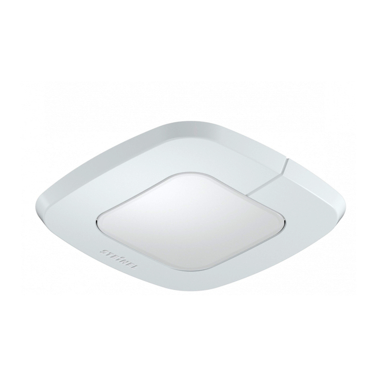
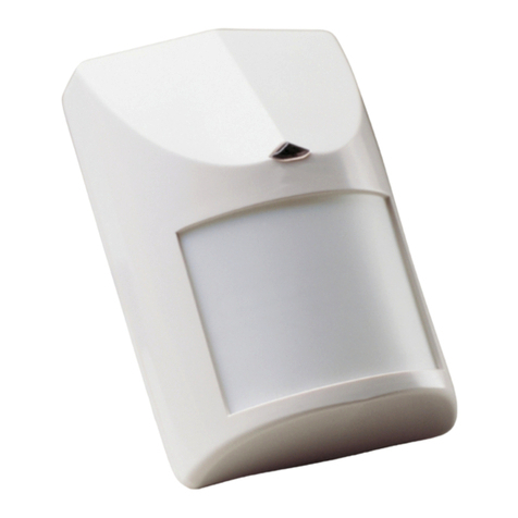
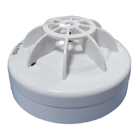
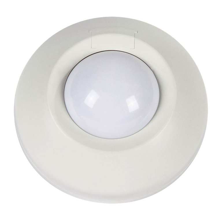
The SS3 products consist of the Models SS3-A, SS3-AN, SS3-AB and SS3-ABN. Each detector is housed
in an ABS white plastic enclosure. The cost-effective Model SS3 fire detector products were designed for
indoor applications and applications where a low profile detector is preferred.
The Model SS3-A and SS3-AN are Multi-Spectrum Optical Fire Detectors which utilize the wide band
infrared (IR), visible (VIS), and ultraviolet (UV) spectral bands. The SS3-A uses a latching relay and the
SS3-AN has a NON-latching relay and auto resets. Both feature a wide 120 degree field of view.
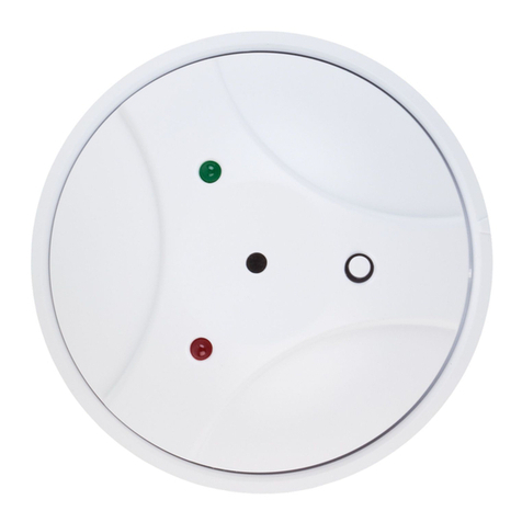
The Model SS3-AB and the SS3-ABN are Ultraviolet (UV) Optical Fire Detectors which feature a wide 180
degree field of view back-facing UV sensor for use in enclosed areas such as wet stations or gas cabinets.
The SS3-AB uses a latching relay and the SS3-ABN uses a NON-latching relay and auto resets.
1.2 Stand-Alone Operation
For Stand-Alone operation, the Model SS3 Detectors may be connected to a FM/UL Approved Fire/Security
Panel. The Model SS3 Detector operates on 24 volts DC. The Model SS3 Detector, when operated in the
Stand-Alone mode, uses its Fire relay to interface to FM/UL Approved Fire /Security Panels
1.3 FS2000 System Operation
For FS2000 System operation, the Model SS3 fire signals are sent digitally to the FS2000 System Controller
using the four wire FS2000 FireBus. The FireBus provides the 24 volts DC power for the Model SS3
Detector and RS-485 digital communication (Refer to Fire Sentry document MN0003 entitled "FS2000 FIRE
EARLY WARNING SYSTEM - INSTALLATION and OPERATIONS GUIDE"). For special remote alarm
applications, users may connect directly to the Model SS3's Fire relay connector.
1.4 Overview
1.4.1 Model SS3 Detector
The Model SS3 Detectors are micro-computerized devices. The Detectors’ logic "brain" alarms to fires
quickly.
There is one LED on the Model SS3 Detectors that indicate the state of the Detector. If the LED blinks
approximately every 10 seconds, then the Detector is in Normal Operation
When a Model SS3 Detector alarms to a fire, it energizes its Fire relay and turns on its red LED.
1.4.2 Testing
The Model SS3 Detectors contain an internal monitoring circuits for self-testing. For testing the Model SS3-A
and SS3-AN Detectors end-to-end for both optical path and window cleanliness, use a Fire Sentry Model
DD85001 UV/IR Test Lamp. The Model SS3-AB and SS3-ABN can be tested using the Model 85001 and
Model 85001(B) UV testers.

SS3-A, SS3-AN, SS3-AB, SS3-ABN
Electro-Optical Fire Detectors Page 2
Installation and Operations Guide
_____________________________________________________________________________
____________________________________________________________________________________________________________________
Fire Sentry Corporation Document No. 1508-002 - Rev B © Copyright 2009 All Rights Reserved
SECTION 2
INSTALLATION
2.1 Installation Procedure
This section describes the installation of the Model SS3 Detector for the Stand-Alone mode. It is
recommended that junction boxes be used to wire the Model SS3 Detectors..
2.1.1 Installation Precautions
The following precautions should be observed during installation of Model SS3 Detectors.
Double-check to make sure that the external electrical power is turned OFF
before connecting to the Model SS3 Detector.
2.1.2 Device Layout
Model SS3 Detectors should be located to cover the specific "fire threat" areas. The Model SS3-A and SS3-
AN Multi-Spectrum Detectors’ field of view is 120º with a range of 30 feet to an industry-standard one square
foot Type B gasoline pan fire. In area coverage applications the Detectors should be located with
overlapping fields of view to insure complete coverage of the area. Detectors should also be located away
from strong RF (Radio Frequency) sources. The Model SS3-AB and SS3-ABN UV Fire Detectors are
designed for enclosed areas and feature a wide 180º field of view.
2.1.3 Wiring Recommendations
Fire Sentry Corporation recommends using junction boxes to help prevent problems with intermittent
connections. Install a junction box near each Model SS3 Detector location. Next, wire each Model SS3
Detector to its junction box. Use screw-down terminal strips inside the junction box to make the connections
to the Detector's terminals and a UL/FM Approved Fire Alarm Panel. Use UL/FM Approved junction boxes
and terminal strips.
Avoid wire splices. However, if wire splices are necessary, Fire Sentry Corporation recommends
soldering all splices. The use of good wiring practices will greatly improve the ease of installation, improve
reliability, and allow easier servicing.
2.1.4 Power Supply Considerations
The Model SS3 Detectors use 12 or 24 volts DC at a maximum current of 40 milliamps. Make sure that the
Panel's power supply can handle the current load of the total number of Model SS3 Detectors connected to
it. For example, if 10 each Model SS3 Detectors are used on one Panel's power supply, (multiply 10 times
40 milliamps), the Panel's power supply must be able to handle at least 400 milliamps. This current load
must also be considered when calculating the Panel's power backup requirements for 24 hour backup.
2.2 Detector Installation
Although not required, Fire Sentry Corporation recommends using the Mounting Bracket when installing the
Model SS3 Detector to a wall or junction box.
a. Choose fasteners for the bracket that will secure it solidly to the type of material at the enclosure
location.
b. Mount the bracket to the wall.
c. Install the Model SS3 Detector enclosure onto the bracket
2.3 Wiring Detectors
The Model SS3 Detector may be wired for use on the FS2000 System or to another Control Panel in the
Standalone configuration. Regardless of which type of Controller or System the Detector is wired to the Fire
Relay will function the same. There are several ways to wire the Fire Relay to a Control Panel or Initiating
Circuit. See the manual for the control panel you will be using for specific wiring information.

SS3-A, SS3-AN, SS3-AB, SS3-ABN
Electro-Optical Fire Detectors Page 3
Installation and Operations Guide
_____________________________________________________________________________
____________________________________________________________________________________________________________________
Fire Sentry Corporation Document No. 1508-002 - Rev B © Copyright 2009 All Rights Reserved
2.3.1 Wiring as Standalone
Connect the 24 volt DC Power Supply wires into the connector and firmly tighten down the slotted screws
with a small screwdriver. DO NOT CONNECT ANY WIRES TO J1 - Pin 2 or J1 - Pin 3. Do NOT over
tighten or the screws may strip or break. Refer to Figure 4, Model SS3 Detector Wiring.
Pin 1 Pin 2 Pin 3 Pin 4
Black Green or Blue White or Yellow Red
GROUND (-) NOT USED NOT USED POWER (+)
2.3.2 Wiring to FS2000 (FireBus)
Connect the FireBus Cable wires into the connector and firmly tighten down the two slotted screws with a
small screwdriver. Do NOT over tighten or the screws may strip or break. Refer to Figure 4, Model SS3
Detector Wiring.
Pin 1 Pin 2 Pin 3 Pin 4
Black Green or Blue White or Yellow Red
GROUND (-) FIREBUS (RX) FIREBUS (TX) POWER (+)
2.3.3. Wiring the Fire Relay
For Stand-Alone or FS2000 systems: Connect the initiating circuit wires to the four pin WECO terminal.
Install the wires into Pins 7 and 8 (for Normally Open relay) or Pins 6 and 7 (for Normally Closed relays) and
firmly tighten down the slotted screws with a small screwdriver. There is an internal 10K ohm resistor
between Pins 5 and 6 for circuits which require an End of Line (Supervision) resistor. One common
configuration is to Jumper Pins 5 to 8 and connect the initiating circuit to Pins 7 and 8.
Refer to Figure 4, Model SS3 Detector Wiring, for more details on relay connections.

SS3-A, SS3-AN, SS3-AB, SS3-ABN
Electro-Optical Fire Detectors Page 4
Installation and Operations Guide
_____________________________________________________________________________
____________________________________________________________________________________________________________________
Fire Sentry Corporation Document No. 1508-002 - Rev B © Copyright 2009 All Rights Reserved
Figure 1
Model SS3 Detector Connection Diagrams
Figure 2
Model SS3 Detectors Wiring

SS3-A, SS3-AN, SS3-AB, SS3-ABN
Electro-Optical Fire Detectors Page 5
Installation and Operations Guide
_____________________________________________________________________________
____________________________________________________________________________________________________________________
Fire Sentry Corporation Document No. 1508-002 - Rev B © Copyright 2009 All Rights Reserved
SECTION 3
MAINTENANCE AND TROUBLESHOOTING
3.1 Personnel
The following will aid in troubleshooting the Model SS3 Detectors. Tests must be performed by qualified
authorized personnel observing standard safety practices. Although the Model SS3 Detector operates on
safe 24 volts DC, the FM/UL Approved Fire Alarm Panel's power supply may operate on a dangerous 120 or
240 volts AC.
WARNING: Hazardous voltages may be present during testing procedures. Serious
injury or death may result if personnel fail to observe safety precautions.
3.2 Cleaning Windowed Enclosures and Detectors
The optical windows on the Model SS3 Detector should be cleaned periodically on a regular maintenance
schedule. For clean applications, this may be every month. However, for extremely dirty applications a
cleaning schedule of every day may be necessary.
Clean the windows on the Model SS3 Detectors whenever they are handled, whenever the windows look
dirty, or whenever the Model SS3 Detector fails to pass an end-to-end test with a Handheld Tester.
Use a blast of an air hose or an oil-free cloth to clean the enclosure windows. Oil degrades the performance
of UV detectors. Occasionally, the use of a solvent such as alcohol may be required. No disassembly of the
Model SS3 Detector is required.
DO NOT USE SILICONE-BASED OR COMMERCIAL WINDOW
CLEANING PRODUCTS. THEY WILL DEGRADE THE MODEL
SS3 DETECTOR PERFORMANCE.
3.3 Model SS3 Detector
CAUTION: Model SS3 Detectors are susceptible to permanent
damage due to electrostatic discharge (ESD).
3.4 Detector Repair
Return a defective detector to the factory for repair service.
THERE ARE NO USER SERVICEABLE PARTS
IN A MODEL SS3 DETECTOR.
If a Model SS3 Detector must be shipped back to the factory for repair, it MUST be packed in static protected
material. An RMA (Return Material Authorization) is required for all returns to the factory. Contact Customer
Service for an RMA number before shipping a unit back to the factory.

SS3-A, SS3-AN, SS3-AB, SS3-ABN
Electro-Optical Fire Detectors Page 6
Installation and Operations Guide
_____________________________________________________________________________
____________________________________________________________________________________________________________________
Fire Sentry Corporation Document No. 1508-002 - Rev B © Copyright 2009 All Rights Reserved
SECTION 4
DETECTOR DATA
Table 1: Model SS3 Detector Connectors - Pinouts
DETECTOR INPUT POWER FIRE RELAY
PIN PIN
1 DC Return or Ground (-) 5 Fire Relay EOL Resistor (10K ohms)
2 FireBus Communication (-) 6 Fire Relay Normally Closed
3 FireBus Communication (+) 7 Fire Relay Common
4 Power (+24 Volts DC) 8 Fire Relay Normally Open

SS3-A, SS3-AN, SS3-AB, SS3-ABN
Electro-Optical Fire Detectors Page 7
Installation and Operations Guide
_____________________________________________________________________________
____________________________________________________________________________________________________________________
Fire Sentry Corporation Document No. 1508-002 - Rev B © Copyright 2009 All Rights Reserved
Mechanical Layouts
P.N. 188424 for SS3-A and SS3-AN P.N. 188424(B) for SS3-AB and SS3-ABN
(Included with Detector) (Included with Detector)
Figure 3
Model SS3 Detector Mounting Brackets

SS3-A, SS3-AN, SS3-AB, SS3-ABN
Electro-Optical Fire Detectors Page 8
Installation and Operations Guide
_____________________________________________________________________________
____________________________________________________________________________________________________________________
Fire Sentry Corporation Document No. 1508-002 - Rev B © Copyright 2009 All Rights Reserved
Figure 4
Model SS3-A and SS3-AN Detectors
Figure 5
Model SS3-AB and SS3-ABN Detectors

SS3-A, SS3-AN, SS3-AB, SS3-ABN
Electro-Optical Fire Detectors Page 9
Installation and Operations Guide
_____________________________________________________________________________
____________________________________________________________________________________________________________________
Fire Sentry Corporation Document No. 1508-002 - Rev B © Copyright 2009 All Rights Reserved
INDEX
C
Cleaning Products, 5
D
Detector
Cleaning, 5
Enclosure, 2
FireBus, 3
LED, 1
Maintenance
Schedule, 5
Mounting Brackets, 7
Pinout, 6
Replacement, 5
SS3-, 8
SS3-CRUV(B), 9
Standalone, 3
Status, 1
Wiring, 3, 4, 6
F
False Alarms, 1
FireBus, 1
FireBus
Wiring, 2
FireLogic, 1
Flame Detector See
Detector, 1
I
Installation, 2
Detector, 3
Enclosure, 2
Precautions, 2
J
Junction Box, 2
L
Layout Planning, 2
M
Maintenance, 5
Mounting Brackets, 7
P
Personnel - Qualified, 5
Power, 2
R
Relay
Fire, 3, 6
S
SS3 See Detector, 1
Stand-Alone, 1
T
Test Source, 1
Theory of Operation, 1
Troubleshooting, 5
W
Wiring
Detector, 4

Thank you for reading this data sheet.
Please contact us for a quotation:
Head Office (UK)
P.O. Box 2124
Chelmsford
Essex CM1 3UP
England
Tel: +44 (0)1245 600 560
Fax: +44 (0)1245 600 030
Email:
General Information/Sales:
info@keison.com
Accounts Department:
accounts@keison.com
Switzerland Office
Zugerstrasse 46
6314 Unterägeri
Zug
Switzerland
Tel: +41 41 541 5877
Fax: +41 41 541 5878
Email:
General Information/Sales:
info@kesn.ch
Accounts Department:
accounts@kesn.ch
USA Office
233 Rogue River Highway #425
Grants Pass
Oregon 97527-5429
USA
Tel: +1 503 206 0941
Fax: +1 541 610 1646
Email:
General Information/Sales:
info@keison.com
Accounts Department:
accounts@keison.com
Latin America Office
World Trade Centre
Apartado 0832-00708
Ciudad de Panamá
República de Panamá
Tel: +507 836 5304
Fax: +507 399 1804
Email:
General Information/Sales:
ventas@keison.com
Accounts Department:
cuentas@keison.com
This manual suits for next models
4
Table of contents
Other Fire Sentry Security Sensor manuals
