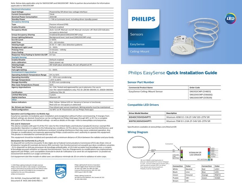
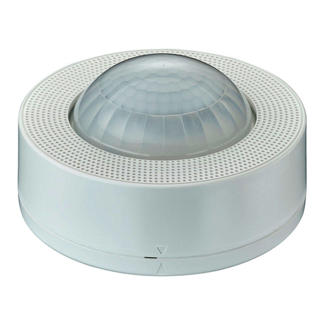
manuals.online logo
Brands
  1. Home
  2. •
  3. Brands
  4. •
  5. Philips
  6. •
  7. Security Sensor
  8. •
  9. Philips DUS804C User manual

Philips DUS804C User manual

DUS804C & DUS804C-SM
Ceiling Mount Universal Sensor Installation Manual
The DUS804C and DUS804C-SM are low profile recessed flush mount 360º ceiling mount sensors that
combine motion detection (PIR), infra red remote control reception (IR) and ambient light level detection
(PE) in the one device.
In applications such as office buildings, lecture theatres, and homes, the DUS804C and DUS804C-SM
universal sensors can be utilised to detect different levels of motion and switch on the lights. In the case of
the standard detection model it can detect movements of items of a size of 700mm x 250mm, whereas the
slight motion version can detect movements of items of a size of 200mm x 200mm –it also has more
detection zones and a faster detection speed (0.5ms vs 1.0ms) –see specifications on page 4 for more
information.
When rooms are unoccupied, lights can be automatically dimmed or switched off to provide energy
savings. The unit also incorporates a segmented click-up bezel surrounding the motion sensor element.
This enables a portion of the sensing field to be readily masked to prevent nuisance detection from
adjacent doorways or corridors. The same sensor provides IR control reception to enable full remote
control over lights, audio-visual equipment and blinds. A range of hand held infra-red transmitters to
complement DUS804 and DUS804C-SM universal sensors are available. In situations where it is critical to
maintain precise lighting control for individual workspaces, such as an office workstation or even air traffic
control centers, the DUS804C facilitates light compensation. Both the DUS804C and DUS804C-SM can
also be placed in an automatic “Daylight Harvesting” mode once motion has been detected for additional
energy savings.
instructions
2DUS804C Installation Manual Rev I.docx
This unit is for indoor use only. This unit is designed for installation in a 64mm diameter hole where the ceiling void is at
least 40mm deep. Select an appropriate indoor mounting location, as detailed in the location guidelines on the following
pages. Note that the product has two functions, and the optimum mounting location for each individual function may
conflict with each other, and may require use of multiple sensors.
DUS804C NETWORK CONNECTIONS:
• Fix the sensor to a firm section of ceiling
• Position the sensor so it is between 2.1 and 4.0m from the floor. Optimum height is 2.4m
• Position the sensor so it is at least 1m away from electrical lighting such as neon and fluorescent lights
• Position the sensor as to avoid exposing it to direct sunlight and heating/cooling sources
• Position the sensor where pedestrian traffic is likely to walk across the detection zones
• Note that for the DUS804C coverage area is rectangular (see Motion Detector coverage diagram)
• When terminated correctly and powered from the Dynet network the sensors LED will flash for 5 min every time a push
button is pressed. This is to confirm the sensor is terminated correctly
• Only after all network devices are confirmed to be terminated correctly can the commissioning of the system begin.
PIR sensor
Network sign
on button & IR
window
Click-up bezel for
motion shield
-RJ option
Recommended Cable Types
Belden: 9503
Garland: MCP3S
Hartland: HCK603
M&M Cable: B2003CS
Dynalite: DYNET-STP-CABLE
STANDARD CABLE CONNECTION
Recommended Cable Colours
Green/White Pair paralleled for GND
Orange/White Pair paralleled for +VE
Blue/White Pair Blue for DATA +
White for DATA -
Light level sensor
motion detector coverage at 2.4m mounting height
DUS804C Installation Manual Rev I.docx 3
photo electric cell mounting location
• Position the sensor so it “sees” a combination of artificial light and natural
Light
• Position the sensor so it is not directly exposed to artificial light or sunlight
• For programming instructions refer to Dynalite Tech Note - Setting up PE
functions
masking regions from motion detection
It is possible to reduce the field of view of the DUS804C-DALI from their normal 3600by use of the in-built
rotating pull out shield. The shield blocks 1200of the field of view, reducing the motion detection field area to
2400. The shield can also be rotated to block any 1200area once the sensor has been installed.
5.66M
2.5M
2.5M
7.42M
Lens pattern –DUS804C
Lens pattern –DUS804C-SM
specifications
4DUS804C Installation Manual Rev I.docx
Warranty policy
Dynalite warrant to the original purchaser for a period of twenty four (24) months from the date of shipment ex-factory of the
equipment that should the equipment prove defective by reason of improper workmanship or material, Dynalite will repair or replace
the same without charge provided the equipment has not been improperly installed, operated, repaired, damaged or abused. The
warranty granted herein is limited to repair or replacement only. Dynalite has the right to substitute any warranty item not on the
current price/equipment list. As far as the law permits, Dynalite shall not be liable for any loss or damage caused to property or
persons arising from any cause whatsoever. This warranty is subject to the return of the equipment to Dynalite, or the Dynalite
authorised distributor who supplied the equipment (the „Supplier‟), by prepaid freight within the twenty four (24) months warranty
period. Where Dynalite, or the Supplier, agree to a site visit during the warranty period and it is found to be an operational problem,
and not subject to warranty in that event, then a field service call out charge will apply. Contact Dynalite or the Supplier for details.
DUS804C Installation Manual Rev G.doc. Specifications and design subject to change without notice. Philips Dynalite manufactured by WMGD Pty Ltd (ABN 33 097 246 921). All rights reserved. Dynalite,
Dimtek, DyNet and DLight and associated logos are the registered trademarks of Dynalite Intelligent Light Pty Ltd. Not to be reproduced without permission.
DUS804C:
Standard Sensitivity
Maximum detection range: 5.0m
Detection Area: up to 7.4m x 5.6m rectangular
(at a height of 2.4m)
Detection speed: 1.0m/s
Detection object: 700mm x 250mm
Detection zones: 64
LED activation indicator
Sensor: Quad element pyro-electric
PE Cell
Range <5 lux to >5000 lux (reflected)
Automatic “Daylight Harvesting” mode
Infra Red Remote Control Receiver
Range up to 6m
LED activation indicator
Can be used with DTK500 series infra red remotes
or other learning IR remotes controls
Controls
Walk test/ LED indicator
Service switch
Control IO
Serial Port –RS485 Dynet 20mA
Terminals
Standard:
5 way removable terminal strip, 1 x 2.5mm2 max
conductor size
-RJ option:
2 x RJ12 network sockets
Operating Environment
0oC to 40oC ambient temperature
0% to 90% RH non condensing
Dimensions
72mm diameter x D 26mm
Weight
Packed weight 0.116kg

This manual suits for next models

1

Other Philips Security Sensor manuals

Philips LRM226500 User manual

Philips

Philips LRM226500 User manual

Philips HP8115 User manual

Philips

Philips HP8115 User manual

Philips LCN3110/05 User manual

Philips

Philips LCN3110/05 User manual

Philips EasyAir SNS212 MC User manual

Philips

Philips EasyAir SNS212 MC User manual

Philips EcoSet SEG101 User manual

Philips

Philips EcoSet SEG101 User manual

Philips EasySense SNS200CMP User manual

Philips

Philips EasySense SNS200CMP User manual

Philips Dynalite DUS704W User manual

Philips

Philips Dynalite DUS704W User manual

Philips EasyAir SNS300 User manual

Philips

Philips EasyAir SNS300 User manual

Philips 17266xx16 Series User manual

Philips

Philips 17266xx16 Series User manual

Philips CHLORIDE COMPAC CXX Series User manual

Philips

Philips CHLORIDE COMPAC CXX Series User manual

Philips OccuSwitch LRM1771 User manual

Philips

Philips OccuSwitch LRM1771 User manual

Popular Security Sensor manuals by other brands

Energy Saving Sensors HC-7B installation manual

Energy Saving Sensors

Energy Saving Sensors HC-7B installation manual

LEGRAND CP Electronics EBDSPIR-DALI2 installation guide

LEGRAND

LEGRAND CP Electronics EBDSPIR-DALI2 installation guide

Optex VX Infinity Series installation instructions

Optex

Optex VX Infinity Series installation instructions

B.E.G. LUXOMAT PD2N-KNX-ST-FT Mounting instructions

B.E.G. LUXOMAT

B.E.G. LUXOMAT PD2N-KNX-ST-FT Mounting instructions

Johnson Controls LC-200S installation instructions

Johnson Controls

Johnson Controls LC-200S installation instructions

Busch-Jaeger Busch-Watchdog 280 ProfessionalLINE installation instructions

Busch-Jaeger

Busch-Jaeger Busch-Watchdog 280 ProfessionalLINE installation instructions

STEINEL IS 360 D TRIO installation instructions

STEINEL

STEINEL IS 360 D TRIO installation instructions

Apollo Smoke Detector XP95 Installation & maintenance guide

Apollo

Apollo Smoke Detector XP95 Installation & maintenance guide

Würth Elast Single Instructions of use

Würth

Würth Elast Single Instructions of use

Elkron DC600S quick guide

Elkron

Elkron DC600S quick guide

Lambrecht aem 8141.6 user manual

Lambrecht

Lambrecht aem 8141.6 user manual

INIM ED100 Product description

INIM

INIM ED100 Product description

STEINEL HPD 2 IP Information

STEINEL

STEINEL HPD 2 IP Information

Wintop iDoorSensor quick start

Wintop

Wintop iDoorSensor quick start

STEINEL PROFESSIONAL IR 180 KNX Information

STEINEL PROFESSIONAL

STEINEL PROFESSIONAL IR 180 KNX Information

Arcom QAM Snare Snoop user manual

Arcom

Arcom QAM Snare Snoop user manual

Elkron IRT600 quick guide

Elkron

Elkron IRT600 quick guide

resideo C554A Product data

resideo

resideo C554A Product data

manuals.online logo
manuals.online logoBrands
  • About & Mission
  • Contact us
  • Privacy Policy
  • Terms and Conditions

Copyright 2025 Manuals.Online. All Rights Reserved.