Simu LED DC Hz User manual

* 2.1 (step 2) and 2.2 (step 1 & 3) only in case of multi channel transmitters (COLOR).
FR
Récepteur Led DC
5112070C
Lire attentivement cette notice
avant toute utilisation
1/1
Programmation du récepteur
2
Caractéristiques
4
Fonctionnement
3
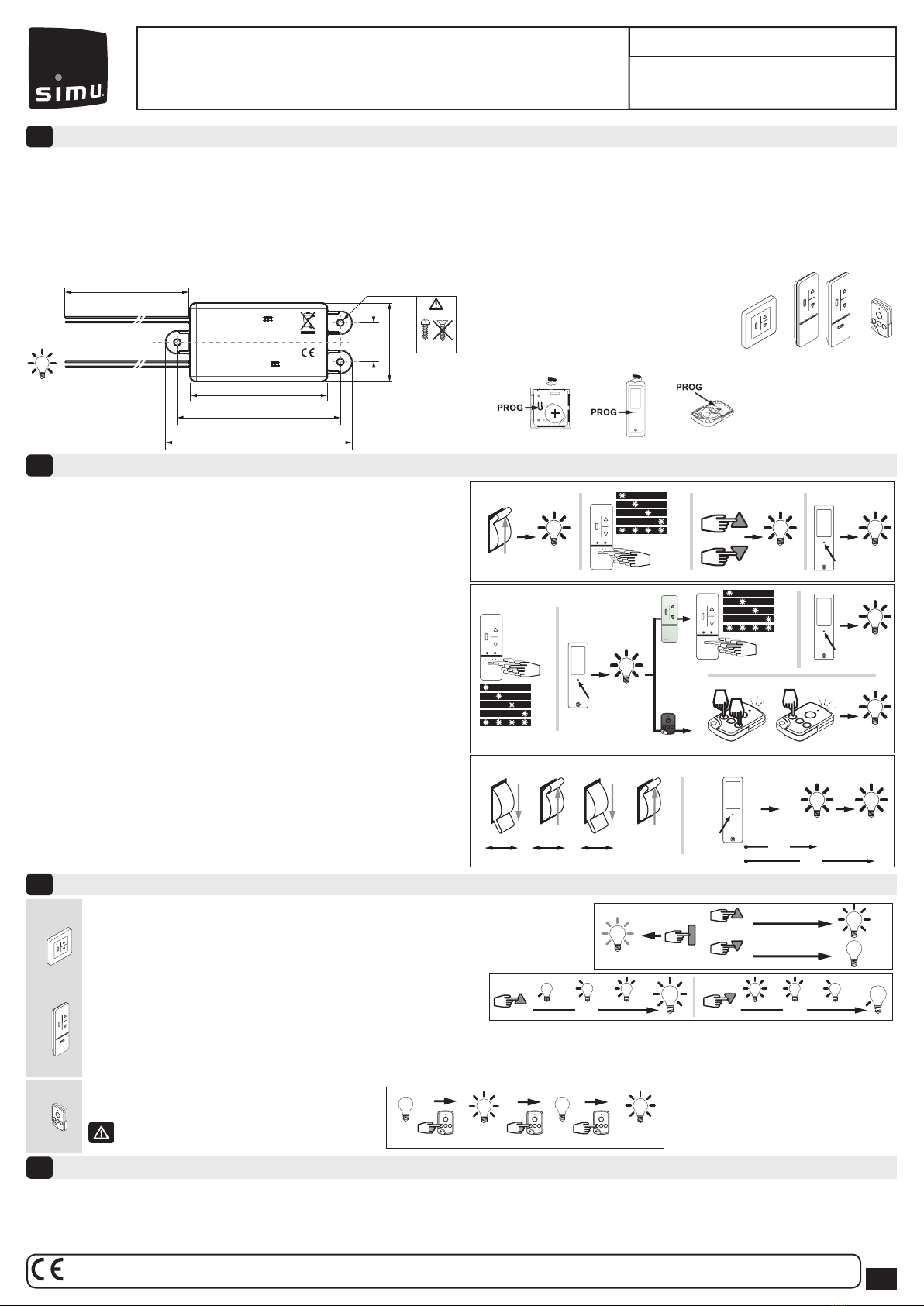
2.1- Programmation du premier émetteur:
1. Mettre le récepteur sous tension (12V), l’éclairage s’allume pendant deux secondes.
2. Sélectionner le canal à programmer*.
3. Appuyer simultanément sur les touches montée et descente d’un émetteur
Hz, l'éclairage s’allume pendant deux secondes.
4. Appuyer 1 sec. sur la touche PROG du nouvel émetteur, l’éclairage s’allume pendant
deux secondes. L’opération est terminée.
2.2- Programmation d’un nouvel émetteur:
1. Sélectionner un canal déjà programmé*.
2. Appuyer 3 sec. sur le bouton PROG de l’émetteur, jusqu’à l’allumage de l’éclairage
pendant deux secondes.
3. Sélectionner le canal à programmer*.
4. Appuyer 1 sec. sur la touche PROG du nouvel émetteur COLOR+,
l’éclairage s’allume pendant deux secondes. L’opération est terminée.
5. Appuyer simultanément sur les 2eme et 4ème boutons de l’émetteur
TSA+ Hz, la Led de l’émetteur TSA+ se met à clignoter.
6. Appuyer ensuite sur le bouton de la TSA+ à programmer, l’éclairage s’allume pendant
deux secondes. L’opération est terminée.
- Pour supprimer un émetteur : répéter les opérations 1 et 2 avec un émetteur programmé,
et les opérations 3,4 ou 5,6 avec l’émetteur (canal) à supprimer.
2.3- Annulation complète de la programmation:
1 - Couper l’alimentation 12V du récepteur pendant 2 secondes.
2 - Rétablir l’alimentation 12V du récepteur pendant 7 secondes.
3 - Couper l’alimentation 12V du récepteur pendant 2 secondes.
4 - Rétablir l’alimentation du récepteur, l’éclairage clignote pendant 2 minutes
5. Appuyer sur la touche PROG de l’émetteur pendant plus de 7 secondes. l’éclairage
s’allume pendant deux secondes deux fois de suite.
- Alimentation: 12VDC (min.: 11V/max.:16V)
- Sortie de commande: 72W à 12V pour eclairages à
incandescence/halogène ou LED.
- Radio: 433.42 MHz
- Température de stockage: -20°C +80°C
- Température d’utilisation: -20°C +70°C (et exceptionellement
jusqu’à +80°C (usage limité à 5 min))
- Sortie protégée contre les surcharges.
- Temporisation éclairage: 3 heures.
- Veiller à recycler les déchets via votre système local de
collecte.
- Conformité européenne: CE
- Indice de protection: IP 55 — Indice IK: IK05.
- Niveau de sécurité : Classe III.
- Ne nécessite pas de refroidissement forcé.
- Bande fréquence d’émission : 433,050 MHz – 434,790 MHz
F: 433,420 MHz
- Puissance maximale transmise : ERP < 10 mW
Allumage/extinction de l’éclairage:
Chaque impulsion sur la touche de commande de l’émetteur commande successivement
l’allumage ou l’extinction de l’éclairage.
Variation de l’intensité lumineuse, impossible avec cet émetteur.
ÉMETTEURS 1 & 2ÉMETTEUR 3
2 s.
≥3 s.
2 s. 2 s.
2 s.
Ch1
Ch2
Ch3
Ch4
Ch5
2 s.
2 s.
+
NEW
NEW
Ch1
Ch2
Ch3
Ch4
Ch5
Ch1
Ch2
Ch3
Ch4
Ch5
PROG
PROG
7 s.
1 s.
PROG
2 s.
1 s.
PROG
new new
2 s.
< 1 s.
12V ON
+
2 s. 7 s. 2 s.
OFF ON OFF ON
1. 2.
1. 2.
3.
3. 4.
5. 6.
4.
1. 2. 3. 4. 5.
2 s.
7 s.
> 1 s.
> 1 s.
50%
0%
100%
stop
0% 0% 100%
< 0,5 s. < 0,5 s. < 0,5 s.
100%
100%
100%
> 0,5 s. > 0,5 s.
3 s. 3 s.
< 0,5 s.
< 0,5 s.
0%
100%
50%
IP
2.1
2.2
2.3
Installation
1
Input 12V DC
IN +12V : rouge
Alimentation
12 VDC
IN GND : noir
Output 12V DC
84 mm
Ø 4,2 mm (0.165 inch)
24 mm (0.94 inch)
48 mm (1.89 inch)
100 mm (3.94 inch)
420 mm (16.50 inch)
114 x 48 x 18,5 mm (4.49 x 1.89 x 0.73 inch)
6 A
OUT LED +12V : marron
OUT LED GND : bleu
AWG18
AWG18
Ø 4 mm
OK
Emetteurs compatibles (12 émetteurs max. par récepteur) :
1 : Emetteur Hz COLOR+ mural
2 : Emetteur Hz COLOR+ mobile 1 / 5 canaux
3: Emetteur TSA+
Emplacement de la touche PROG sur les émetteurs Hz
1
1
2
2
3
3
Instructions de sécurité:
- Ne pas percer le récepteur. La ligne alimentant le récepteur doit être équipée d'un dispositif de sectionnement et une protection contre les surintensités.
Préconisations:
- Ce récepteur n'est pas protegé contre les surtensions (Load dump).
- L’utilisation d’un appareil radio utilisant la même fréquence (433,42MHz) peut dégrader les performances de ce produit (ex.: casque radio Hi-Fi).
- Respecter une distance minimum de 20cm entre deux récepteurs Hz. Respecter une distance minimum de 30cm entre un récepteur Hz et un émetteur Hz.
- Ce produit Simu doit être installé par un professionnel de la motorisation et de l’automatisation de l’habitat auquel cette notice est destinée. L’installateur doit, par ailleurs, se
conformer aux normes et à la législation en vigueur dans le pays d’installation et informer ses clients des conditions d’utilisation.
- Le produit ne constitue pas une protection et isolation électrique, un appareil TBTS (très basse tension de sécurité) en amont doit être présent an de protéger les biens et les
personnes s'accordant avec les codes électriques locaux et nationaux.
US PAT n°7852765/8189620
OR
Par la présente SIMU déclare que l'équipement radio couvert par ces instructions est conforme aux exigences de la Directive Radio 2014/53/UE et aux autres
exigences essentielles des Directives Européennes applicables. Le texte complet de la déclaration UE de conformité est disponible sur www.simu.com.
Allumage/extinction de l’éclairage:
Un appui bref (<0,5 sec.) sur la touche ▲ allume l’éclairage (100%).
Un appui bref (<0,5 sec.) sur la touche ▼ éteint l’éclairage (0%).
Un appui bref (<0,5 sec.) sur la touche Stop commande l’éclairage en position intermédiaire (ex: 50%).
Variation de l’intensité d’éclairage:
Un appui maintenu (>0.5 sec) sur les touches ▲ ou ▼ d’un émetteur Color +,
permet d’augmenter ou de diminuer l’intensité lumineuse. (5% tous les 0,16sec,
0% au minimum, 100% au maximum).
Enregistrement /commande/suppression d’une position intermédiaire:
- Enregistrement : Maintenir l’appui sur la touche ▲ ou▼ jusqu’à ce que l’intensité de l’éclairage rejoint le niveau souhaité. Appuyer ensuite 5s sur la touche
STOP. L’éclairage s’allume pendant deux secondes.
- Commande : Un appui bref (<0.5 sec) sur la touche STOP, allume l’éclairage à l’intensité lumineuse mémorisée comme position intermédiaire.
- Suppression : Un appui bref (<0.5 sec) sur la touche STOP, allume l’éclairage à l’intensité lumineuse mémorisée comme position intermédiaire. Appuyer
ensuite 5s sur la touche STOP. L’éclairage s’allume pendant deux secondes.
SIMU S.A.S. au capital de 5 000 000 € - Z.I. Les Giranaux - BP71 - 70103 ARC-LÈS-GRAY CEDEX - FRANCE - RCS VESOUL B 425 650 090 - SIRET 425 650 090 00011 - n° T.V.A CEE FR 87 425 650 090
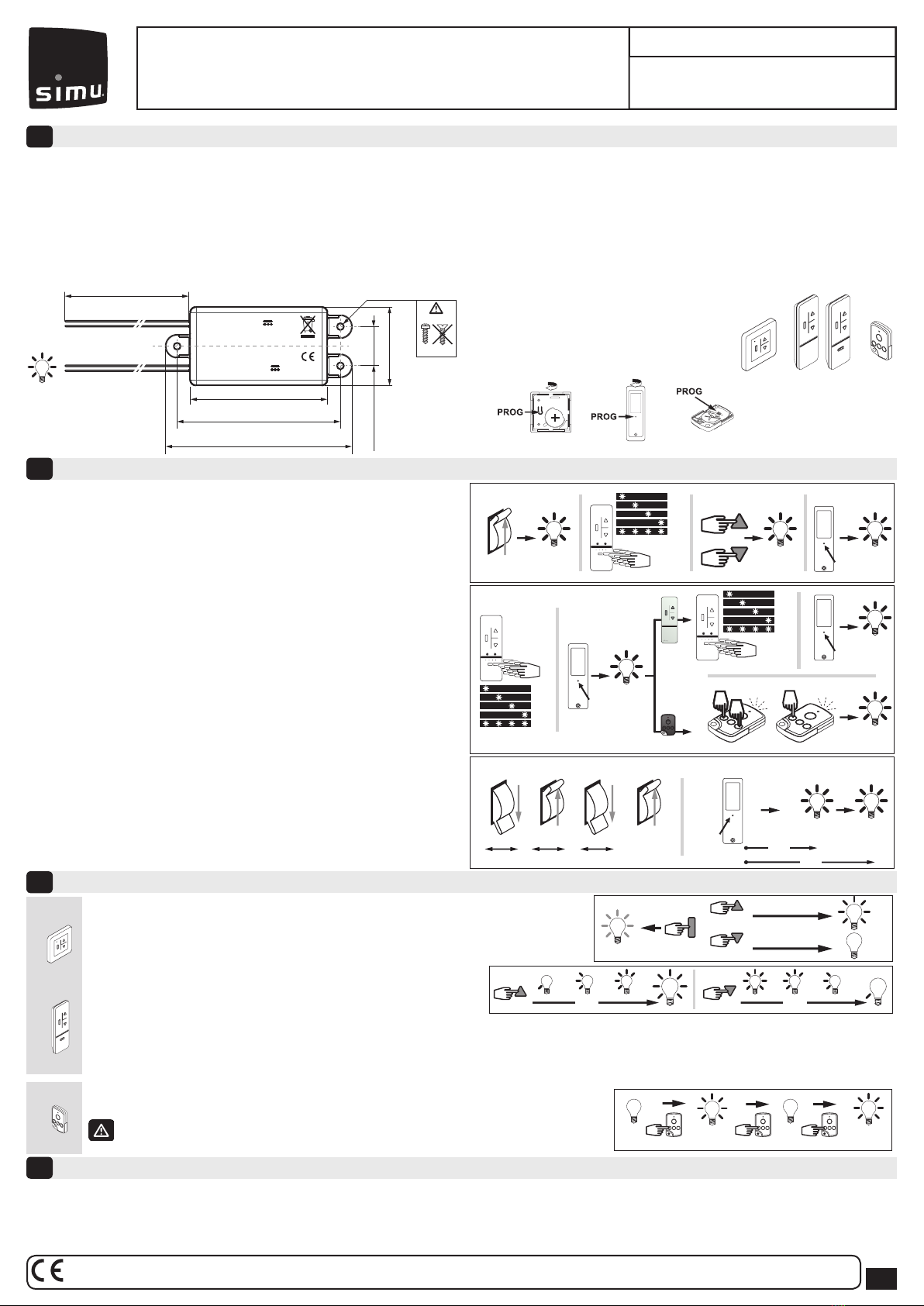
2.1- Programming the rst transmitter:
1.
Switch the 12 V power supply of the receiver ON. The Led ramp will turn on for two seconds.
2. Select the desired channel*.
3. Press simultaneously the UP and DOWN buttons of the transmitter, the Led ramp
will turn ON for two seconds.
4. Press the PROG button 1 second, the Led ramp will turn ON for two seconds.
The operation is completed.
2.2- Adding a new transmitter:
1. Select a channel already programmed*.
2. Press for 3 seconds the program button (PROG) until the Led ramp turns ON
for two seconds.
3. Select the channel of the new transmitter you wish to add*.
4. Press the PROG button for 1 second, the Led ramp will turn ON for two seconds.
The operation is completed.
5. Press simultaneously the 2nd and 4th buttons on the TSA+ you wish to add as shown
in the picture, the TSA+’s Led will blink.
6- Press the desired channel (button) on the TSA+ you wish to add, the Led ramp turn
on for two seconds. The operation is completed.
To remove a transmitter (Channel): repeat stages 1, 2 with a transmitter (Channel)
that currently controls the receiver and stage 3,4 or 5,6 with the transmitter (Channel)
to be deleted from the receiver).
2.3- Cancelling programming:
1. Switch o the 12V power supply to the receiver for 2 seconds.
2. Switch the power to the receiver back on for 7 seconds.
3. Switch o the power supply to the receiver for 2 seconds.
4. Switch the power to the receiver back on. The Led ramp will blink for 2 minutes.
5. Press on the transmitter's PROG button for more than 7 seconds, the Led ramp will
turn ON for 2 seconds twice in succession. The operation is completed.
* 2.1 (step 2) and 2.2 (step 1 & 3) only in case of multi channel transmitters (COLOR).
EN
LED DC Hz Receiver
5112070C
Carefully read these instructions
before any use.
1/1
Programming
2
Technical characteristics
4
Functioning
3
Led ramp control:
A short press (<0,5 sec.) on the ▲ button to turn the Led ramp on (100%).
A short press (<0,5 sec.) on the ▼ button to turn o the Led ramp (0%).
A short press (<0,5 sec.) on the Stop button to turn ON the Led ramp at the Intermediate Position (ex: 50%).
Led ramp dimming:
A long press (> 0,5 sec.) on the ▲ or ▼ keys increase or decrease the level
of the Led ramp (step: 5% each 0.16 sec, 0% at minimum, 100% at maximum).
Recording/controlling/deleting intermediate position:
- Recording : Press on the ▲ or ▼ button until you reach the desired light level, then press for 5 seconds on the Stop button, the Led ramp will turn ON for 2 seconds.
- Controlling : A short press of the Stop button will the turn ON Led ramp to the memorized intermediate level.
- Deleting : A short press on Stop button and the Led ramp will turn ON to the memorized level. Then press for 5 seconds on the Stop button, the Led ramp will turn on
for 2 seconds.
- Power supply: 12VDC (min.: 11V/max.:16V)
- Control output: 72W at 12V for incandescent/halogen or Led
bulbs.
- Radio: 433.42 MHz
- Storage temperature : -20°C +80°C
- Temperature of use: -20°C +70°C (and exceptionally up to
+80°C (use limited to 5 min))
- Over-current protection on the output.
- Lighting time-out 3 hours.
- Please ensure you dispose of waste products using your
local refuse collection system.
- European compliance: CE
- Protection index : IP 55 — IK Index: IK05.
- Safety level : Class III.
- No need for forced cooling system.
- Frequency range: 433,050 MHz – 434,790 MHz F: 433,420
MHz
- Max power used: ERP < 10 mW.
Led ramp control:
Each press of the button toggles between ON and OFF
No dimming possible with this transmitter.
TRANSMITTERS 1 & 2TRANSMITTER 3
2 s.
≥3 s.
2 s. 2 s.
2 s.
Ch1
Ch2
Ch3
Ch4
Ch5
2 s.
2 s.
+
NEW
NEW
Ch1
Ch2
Ch3
Ch4
Ch5
Ch1
Ch2
Ch3
Ch4
Ch5
PROG
PROG
7 s.
1 s.
PROG
2 s.
1 s.
PROG
new new
2 s.
< 1 s.
12V ON
+
2 s. 7 s. 2 s.
OFF ON OFF ON
1. 2.
1. 2.
3.
3. 4.
5. 6.
4.
1. 2. 3. 4. 5.
2 s.
7 s.
> 1 s.
> 1 s.
50%
0%
100%
stop
0% 0% 100%
< 0,5 s. < 0,5 s. < 0,5 s.
100%
100%
100%
> 0,5 s. > 0,5 s.
3 s. 3 s.
< 0,5 s.
< 0,5 s.
0%
100%
50%
IP
2.1
2.2
2.3
Installation
1
Input 12V DC
IN +12V : red
Power supply
12 VDC
IN GND : black
Output 12V DC
84 mm
Ø 4,2 mm (0.165 inch)
24 mm (0.94 inch)
48 mm (1.89 inch)
100 mm (3.94 inch)
420 mm (16.50 inch)
114 x 48 x 18,5 mm (4.49 x 1.89 x 0.73 inch)
6 A
OUT LED +12V : brown
OUT LED GND : blue
AWG18
AWG18
Ø 4 mm
OK
Compatible transmitter (max. 12 per receiver):
1: COLOR+ Wall Hz transmitter
2: COLOR+ 1/5 mobile Hz transmitter
3: TSA+ transmitter
USA : use only FCC transmitter range.
Location of the PROG button on Hz transmitters:
1
1
2
2
3
3
Mandatory instructions:
- Take care not to drill through the Hz DC receiver.
- The receiver power supply line must be equipped with a sectioning, and an over-current protection.
Recommendations:
- This receiver is not protected against load dump.
- Radio appliance using the same frequency (433.42 MHz) may reduce our product’s performance (Ex: Wireless headphones).
- Keep a minimum distance of 8 in. (0.2m) between two Hz receivers. Keep a minimum distance of 12 in. (0.3m) between Hz receivers and Hz transmitters.
- The receiver must be installed by a licensed electrician or a qualied professionnal of motorisation or automation in accordance with these instructions and with local and national
electrical codes.
- The product does not perform electrical insulation and protection, a SELV (Safety Extra Low Voltage) device upstream must be present in order to protect property and persons
according with local and national electrical codes.
US PAT n°7852765/8189620
OR
SIMU hereby declares that the radio equipment covered by these instructions is in compliance with the requirements of Radio Directive 2014/53/EU and the other
essential requirements of the applicable European Directives. The full text of the EU declaration of conformity is available at www.simu.com.
SIMU S.A.S. au capital de 5 000 000 € - Z.I. Les Giranaux - BP71 - 70103 ARC-LÈS-GRAY CEDEX - FRANCE - RCS VESOUL B 425 650 090 - SIRET 425 650 090 00011 - n° T.V.A CEE FR 87 425 650 090
1/1
Programmierung
2
Eigenschaften
4
Funktion der Steuerung
3
2.1- Programmierung des ersten Senders:
1.
Schalten Sie die 12 V Versorgung des Empfängers ein. Die LED´s leuchten für 2 Sekunden
2. Wählen Sie den gewünschten Kanal aus*.
3. Drücken Sie die AUF und AB Tasten des Senders gleichzeitig, die LED´s leichten für
2 Sekunden.
4. Drücken Sie die PROG Taste für 1 Sekunde, die LED´s leuchten für 2 Sekunden.
Die Programmierung ist abgeschlossen
2.2- Hinzufügen eines neuen Senders:
1. Wählen Sie den bereits programmierten Kanal aus*.
2. Drücken Sie 3 Sekunden die PROG Taste, bis die LED´S für 2 Sekunden leuchten.
3. Wählen Sie den neuen Kanal aus*.
4. Drücken Sie die PROG Taste für 1 Sekunde, die LED´s leuchten für 2 Sekunden.
Die Programmierung ist abgeschlossen. Gehen Sie zum Punkt 3 um einen COLOR+
Sender hinzuzufügen, oder zu Punkt 5 für einen TSA+ Sender.
5. Wie auf dem Bild gezeigt, drücken Sie die 2te und 4te Taste auf dem neuen TSA+
gleichzeitig. Die LED auf dem TSA+ blinkt.
6. Drücken Sie die Taste für den gewünschten kanal auf dem neuen TSA+, die LED`s
leutchten für 2 Sekunden. Die Programmierung ist abgeschlossen.
Um einen Sender (oder Kanal) zu löschen, wiederholen Sie Punkt 1& 2 mit dem
Sender, der weiterhin erhalten bleibt und Punkt 3&4 oder 5&6 mit dem Sender
der gelöscht werden soll.
2.3- Löschen der Programmierung:
1. 12V Empfängerversorgung 2 Sekunden lang ausschalten.
2. Empfängerversorgung 7 Sekunden lang wieder herstellen.
3. Empfängerversorgung 2 Sekunden lang ausschalten.
4. Empfängerversorgung wieder herstellen. Die LED`s gehen für zwei Sekunden an.
5. Über 7 Sekunden lang die “PROG” –Taste betätigen, Die LED`s gehen zwei Mal
nacheinander für je zwei Sekunden an. Der Empfänger ist komplett gelöscht.
Schalten der LED's:
Kurzes Drücken (<0,5 sec.) auf die ▲ Taste schaltet die LED´s ein (100%).
Kurzes Drücken(<0,5 sec.) auf die ▼ Taste schaltet die LED´s aus (0%).
Kurzes Drücken(<0,5 sec.) auf die STOP Taste schaltet die LED´s auf Zwischenposition (z.B. 50%)
Dimmen der LED's:
Langes Drücken (>0.5sec.) auf die ▲ oder▼ Taste erhöht oder senkt den
Level der LED´s (5% alle 0.16 sec, 0% Minimum, 100% Maximum):
Speichern/Kontrolle/Löschen der Zwischenposition:
- Speichern: Drücken Sie die ▲ oder ▼ Taste bis der gewünschte Helligkeitslevel erreicht ist. Anschliessend halten Sie die STOP Taste 5 Sekunden gedrückt, die LED´s
leuchten für 2 Sekunden.
- Kontrolle: Kurzes Drücken auf die STOP Taste lässt die LED´s in der gewünschten Helligkeit leuchten.
- Löschen: Kurzes Drücken auf die STOP Taste lässt die LED´s in der gewünschten Helligkeit leuchten. Drücken Sie anschliessend für 5 Sekunden die STOP Taste, die
LED`s leuchten für 2 Sekunden
- Spannung: 12VDC (min.: 11V/max.:16V)
- Steuerungsausgang: 72W bei 12V mit Glüh-,Halogenlampen
oder LED.
- Funkanlage: 433.42 MHz
- Lagerungstemperatur: -20°C +80°C
- Betriebstemperatur: -20°C +70°C (im Extremfall +80°C
(maximal 5 min))
- Überspannungsschutz am Ausgang.
- Einschaltzeit auf 3 Stunden begrenzt,
- Abfälle müssen über Ihr lokales Sammelsystem entsorgt
werden
- EG- Konformität: CE
- Schutzart: IP 55 — IK Index: IK05
- Schutzklasse : III.
- Keine externe Kühlung notwendig
- Frequenzband: 433,050 MHz - 434,790 MHz F. 433,420 MHz
- Eektive maximale Sendeleistung : ERP < 10 mW.
Schalten der LED's:
Jede Betätigung der Steuertaste des Senders schaltet die Beleuchtung der Reihe nach ein bzw. aus.
Mit diesem Sender ist Dimmen nicht möglich.
SENDER 1 & 2SENDER 3
2 s.
≥3 s.
2 s. 2 s.
2 s.
Ch1
Ch2
Ch3
Ch4
Ch5
2 s.
2 s.
+
NEW
NEW
Ch1
Ch2
Ch3
Ch4
Ch5
Ch1
Ch2
Ch3
Ch4
Ch5
PROG
PROG
7 s.
1 s.
PROG
2 s.
1 s.
PROG
new new
2 s.
< 1 s.
12V ON
+
2 s. 7 s. 2 s.
OFF ON OFF ON
1. 2.
1. 2.
3.
3. 4.
5. 6.
4.
1. 2. 3. 4. 5.
2 s.
7 s.
> 1 s.
> 1 s.
50%
0%
100%
stop
0% 0% 100%
< 0,5 s. < 0,5 s. < 0,5 s.
100%
100%
100%
> 0,5 s. > 0,5 s.
3 s. 3 s.
< 0,5 s.
< 0,5 s.
0%
100%
50%
IP
2.1
2.2
2.3
Installation
1
Input 12V DC
IN +12V : Rot
Spannungsversorgung
12 VDC
IN GND : Schwarz
Output 12V DC
84 mm
Ø 4,2 mm (0.165 inch)
24 mm (0.94 inch)
48 mm (1.89 inch)
100 mm (3.94 inch)
420 mm (16.50 inch)
114 x 48 x 18,5 mm (4.49 x 1.89 x 0.73 inch)
6 A
OUT LED +12V : Braun
OUT LED GND : Blau
AWG18
AWG18
Ø 4 mm
OK
Kompatible Sender (max. 12 Sender per Empfänger):
1: Hz Wandsender COLOR+
2: Hz 1 und 5 Kanal-Sender COLOR+
3: TSA +
Anordnung der PROG Taste am Hz-Sender:
1
1
2
2
3
3
Wichtige Hinweise:
- Bei der Montage ist darauf zu achten, dass der Hz-Empfänger nicht durchgebohrt wird
- Die Stromversorgung des Empfängers muss mit einer schnell lösbaren Verbindung und einer Überstromsicherung
Empfehlungen:
- Dieser Empfänger ist nicht gegen Überlastung geschützt (Load dump).
- Ein Radiogerät, das die gleiche Frequenz nutzt (433,42 MHz), könnte die Leistung des Produkts stören (z.B. Hi-Fi Radio- Kopfhörer).
- Zwischen 2 Hz-Empfängern ist ein Minimalabstand von 20 cm einzuhalten. Zwischen einem Hz- Empfänger und einem Hz-Sender ist ein Minimalabstand von 30 cm einzuhalten.
- Dieser Empfänger muss von einer fachlich qualizierten Person (Elektrofachkraft nach DIN VDE 1000-10) für Antriebe und Automatisierungen im Haustechnikbereich installiert
werden, für die diese Anleitung bestimmt ist.
- Das Produkt selbst verfügt über keine elektrische Isolierung und keinen elektrischen Schutz. Es muss ein SELV- (Safety Extra Low Voltage) Netzteil vorgeschaltet werden, um
Eigentum und Personen entsprechend den lokalen und nationalen Vorschriften und Normen zu schützen.
*2.1 (Punkt 2) and 2.2 (Punkt 1 & 3) nur bei Mehrkanalsendern (COLOR+).
ODER
SIMU erklärt hiermit, dass das in dieser Anleitung beschriebene Produkt die Anforderungen der Funkanlagenrichtlinie 2014/53/EU sowie die grundlegenden Anforderungen
anderer geltender europäischer Richtlinien erfüllt. Der vollständige Text der EU-Konformitätserklärung ist unter der Internetadresse www.simu.com verfügbar.
DE
LED DC Hz EMPFÄNGER
5112070C
Bitte gründlich vor dem Einbau lesen
US PAT n°7852765/8189620
SIMU S.A.S. au capital de 5 000 000 € - Z.I. Les Giranaux - BP71 - 70103 ARC-LÈS-GRAY CEDEX - FRANCE - RCS VESOUL B 425 650 090 - SIRET 425 650 090 00011 - n° T.V.A CEE FR 87 425 650 090

*2.1 (paso 2) y 2.2 (paso 1 y 3) solo para emisores multicanal (COLOR+).
1/1
Características técnicas
4
Funcionamiento
3
Control de la Led ramp:
Una pulsación breve (menos de medio segundo) del botón ▲ para encender la luz (100 %).
Una pulsación breve (menos de medio segundo) del botón ▼ para apagar la luz (0%).
Una pulsación breve (menos de medio segundo) del botón Stop para encender la luz en
la posición intermedia (ej. 50%).
Led ramp dimming:
Una pulsación larga (>0.5sec.) en las teclas ▲ o ▼ incrementa o reduce el
nivel de iluminación de Led ramp (pulsación: 5% cada 0.16 sec, 0% al mínimo,
100% al máximo).
Memorizar, activar y eliminar una posición preferida:
- Memorizar : Pulsar el botón ▲ o ▼ hasta alcanzar el nivel deseado de iluminación, después pulsar 5 segundos la tecla Stop, la Led ramp se encenderá durante 2 segundos.
- Activar: Una pulsación breve en el botón Stop encenderá la Led ramp al nivel de iluminación programado.
- Eliminar : Pulsar brevemente el botón Stop la Led ramp se encenderá alcazando la posición programada. Pulsar durante 5 segundos la tecla Stop, la Led ramp se
apagará durante 2 segundos.
- Alimentación: 12 VCC (mín: 11 V/ máx: 16 V)
- Salida de control: 72 W a 12 V para bombillas incandes-
centes/halógenas o LED.
- Radio: 433,42 MHz
- Temperatura de almacenamiento: de -20°C a + 80°C
- Temperatura de uso: de -20°C a +70°C (y, excepcionalmente,
hasta +80°C (uso limitado a 5 min))
- Protección contra sobrecorrientes en la salida.
- Tiempo de desconexión de las luces: 3 horas.
- Asegúrese de eliminar los productos de desecho mediante su
sistema de recogida de desechos local.
- Conformidad europea: CE
- Índice de protección: IP 55 — Índice IK: IK05
- Nivel de securidad : Clase III.
- No es necesario contar con un sistema de enfriamiento
forzado.
- Banda de frecuencia de transmisión : 433,050 MHz –
434,790 MHz F: 433,420 MHz
- Potencia radiada aparente : ERP< 10 mW.
Control de la rampa Led:
Cada pulsación del botón alterna entre encendido y apagado entre encendido y apagado.
Las luces no se pueden atenuar con este emisor.
EMISORES 1 & 2EMISOR 3
> 1 s.
> 1 s.
50%
0%
100%
stop
0% 0% 100%
< 0,5 s. < 0,5 s. < 0,5 s.
100%
100%
100%
> 0,5 s. > 0,5 s.
3 s. 3 s.
< 0,5 s.
< 0,5 s.
0%
100%
50%
IP
Instalación
1
Input 12V DC
IN +12V : roso
Alimentación
12 VDC
IN GND : negro
Output 12V DC
84 mm
Ø 4,2 mm (0.165 inch)
Ø 4 mm
24 mm (0.94 inch)
48 mm (1.89 inch)
100 mm (3.94 inch)
420 mm (16.50 inch)
114 x 48 x 18,5 mm (4.49 x 1.89 x 0.73 inch)
6 A
OUT LED +12V : marron
OUT LED GND : azul
AWG18
AWG18
OK
Emisores compatibles (máx. 12 por receptor):
1: Emisor Mural Hz COLOR+
2: Emisor Hz portátil 1/5 COLOR+
3: Emisor TSA+
Ubicación de la tecla PROG en los Emisor Hz:
1
1
2
2
3
3
Mandatory instructions:
- Tenga cuidado en no perforar el receptor Hz CC.
- La alimentación del receptor debe estar equipada con una desconexión rápida y protección ante subidas de corriente.
Recomendaciones:
- Este receptor no está protegido contra picos de tensión (Load dump).
- Los aparatos de radio que utilicen la misma frecuencia (433,42 MHz) pueden inuir en el correcto funcionamiento del receptor. (ej.auriculares hi)
- Mantenga una distancia mínima de 8 pulgadas (20 cm) entre dos receptores Hz. Mantenga una distancia mínima de 12 pulgadas (30 cm) entre los receptores Hz y los transmisores
- El receptor tiene que ser instalado por un electricista cualicado o una persona cualicada en la motorización o automatización en acuerdo con estas instrucciones y con los códigos
eléctricos locales y nacionales.
- El producto no satisface al aislamiento y proteccion electrico. Un dispositivo precedente MBTS (Muy Baja Tensión de Seguridad) debe estar presente con el n de proteger la propie-
dad y las personas en acuerdo con los códigos eléctricos locales y nacionales.
Programación
2
2.1- Programación del primer Emisor:
1.
Conecte la alimentación de 12 V del receptor. Se encenderá la Led ramp durante 2 segundos.
2. Seleccionar el canal por programar
3. Pulsar simultáneamente en las teclas subida y descenso de un emisor Hz. la rampa Led se
encenderá durante 2 segundos
4. Pulsar aproximadamente 1 segundo en la tecla PROG del emisor que desee programar; la
Led ramp se encenderá durante 2 segundos. La programación ha nalizado.
2.2- Añadir un nuevo emisor:
1. Seleccionar el canal por programar *.
2. Pulsar aproximadamente 3 segundos en la tecla PROG del emisor la Led ramp se
enciende durante dos segundos. Ir a paso 3 para añadir un Color + emisor, o paso
5 para añadir TSA+ emisor.
3 Seleccione el canal del nuevo transmisor que desee agregar *.
4. Pulsar 1 segundo aproximadamente en la tecla PROG, la Led ramp se encenderá du-
rante 2 segundos. La programación ha nalizado.
5. Pulse simultáneamente los botones 2 y 4 del nuevo TSA+, como se indica en la imagen;
la Led ramp parpadeará.
6. Pulse el canal deseado (botón) del nuevo TSA+ que desee añadir; la luz se encenderá
durante 2 segundos. La programación ha nalizado.
Para eliminar un emisor (canal): repita los pasos 1 y 2 con un emisor (canal) que controle en ese
momento el receptor; y los pasos 3 y 4 o 5 y 6 con el emisor (canal) que desee borrar de la memoria.
2.3- Cancelación de la programación:
1. Desconecte la alimentación 12 V del receptor durante 2 segundos.
2. Vuelva a conectar la alimentación del receptor durante 7 segundos.
3. Desconecte la alimentación del receptor durante 2 segundos.
4. Vuelva a conectar la alimentación del receptor. La Led ramp parpadeará durante 2 minutos.
5. Pulsar más de 7 segundos en la tecla PROG del emisor, las Led ramp se encenderán
durante dos segundos dos veces consecutivas. La programación ha nalizado.
2 s.
≥3 s.
2 s. 2 s.
2 s.
Ch1
Ch2
Ch3
Ch4
Ch5
2 s.
2 s.
+
NEW
NEW
Ch1
Ch2
Ch3
Ch4
Ch5
Ch1
Ch2
Ch3
Ch4
Ch5
PROG
PROG
7 s.
1 s.
PROG
2 s.
1 s.
PROG
new new
2 s.
< 1 s.
12V ON
+
2 s. 7 s. 2 s.
OFF ON OFF ON
1. 2.
1. 2.
3.
3. 4.
5. 6.
4.
1. 2. 3. 4. 5.
2 s.
7 s.
2.1
2.2
2.3
O
ES
Receptor de LED Hz CC
5112070C
Leer atentamente este documento
antes de cualquier uso
US PAT n°7852765/8189620
En virtud del presente documento SIMU declara que el equipo de radio cubierto por estas instrucciones es conforme a las exigencias de la Directiva de radio 2014/53/UE y las demás
exigencias básicas de las Directivas europeas aplicables. El texto completo de la declaración UE de conformidad se encuentra disponible en www.simu.com.
SIMU S.A.S. au capital de 5 000 000 € - Z.I. Les Giranaux - BP71 - 70103 ARC-LÈS-GRAY CEDEX - FRANCE - RCS VESOUL B 425 650 090 - SIRET 425 650 090 00011 - n° T.V.A CEE FR 87 425 650 090
Table of contents
Languages:
Other Simu Receiver manuals


