SincMill SCM-1148L Quick setup guide
Performance Home Gym
Model: SCM-1148L
Assembly and Use Instructions
NOTE:
Please read all instructions
carefully before using this
product
Contents
Important Precautions
Component - Parts
Components - Fixings
Assembly
Operation and Adjustment
Maintenance
Parts List
Model
SCM-1148L
Retain This
Manual for
Reference
20221107
OWNER'S
MANUAL


Contents
Before you Begin
1
Safety Information
2
Components-Parts
3-4
Components-Fixings
5
Assembly Instructions
6-22
Explosion diagram
23
Exercise Information
24-27
Parts List
28-29


1
Thank you for selecting SCM-1148L Multi Purpose Home Gym. For your safety and benefit, read this manual
carefully before using the machine. As a manufacturer, we are committed to provide you complete customer
satisfaction. If you have any questions, or find there are missing or damaged parts, we guarantee you complete
satisfaction through direct assistance from our factory. To avoid unnecessary delays, please contact our after-
sales mailbox. Our customer service staff will assist you immediately.
Before starting the installation, be sure to check that all parts are intact, as there
is a very small chance of missing parts or shipping damage, which will halt the
installation process. If any parts are missing or damaged, please contact the after-
sales email address below, and professional customer servicewill sincerely serve
you to ensure your satisfaction.
This manual will update some details from time to time. The latest version of the electronic manual can be
downloaded from the product details page. Combined with this manual and the installation video tutorial in the
product details page, it can be easily understood and installed. Happy fitness.
After-sales email: Aurora23196 outlook.com
Before you Begin
Additional Notes:
Because the products are large and heavy, they were shipped in four boxes with different tracking
numbers, so they may not be delivered on the same day. Because of the rules of the shopping platform, I can
only upload one tracking number. If you need all the tracking numbers, you can contact the seller on the
shopping platform to get them.
Page 23 has all the part numbers for this machine and some parts are pre-assembled on the part assembly
on page 3,4. Please refer to pages 3,4,5 for part number checks prior to installation. Difficult to distinguish
parts have been placed on plastic cardboard and are numbered. Other parts can be easily identified by their
shape and are not numbered.
Part #102 is a pair of weight covers made of nylon. They were folded into a square and placed in box #1.
Because weight covers made of other materials tend to fall in shipping and cause damage or deformation,
weight covers made of soft materials will be more suitable for express shipping.
Thank you for your patience and understanding.
Have a good day.

2
This exercise equipment is built for optimum safety. However, certain precautions apply whenever you
operate a piece of exercise equipment. Be sure to read the entire manual before you assemble, operate
or use this equipment.
Assembly
•The product must be installed on a stable and level
surface.
•Assemble the item as close to its final position
(in the same room) as possible.
•Make sure you have enough space to layout the
parts before starting.
•Keep children and animals away from the exercise
area, small parts could pose a choking hazard if
swallowed.
•Dispose of all packaging carefully and responsibly.
•Check you have all the components and tools
listed in the parts list, bearing in mind that, for
ease of assembly, some components are pre-
assembled.
•The assembly of this equipment is best carried out
by 2 people.
Use
•It is the responsibility of the owner to ensure that all
users of this product are properly informed as to how
to use this product safely.
•This product is intended for domestic use only.
Do not use in any commercial, rental, or institutional
setting.
•Use the equipment only for intended use, as
described in this manual. Do not use attachments not
recommended by the manufacturer.
• Keep this equipment indoors, away from moisture
and dust. Do not put the equipment in a garage,
outbuilding, covered patio, or near water.
•Your product is intended for use in clean dry
conditions. You should avoid storage in excessively
cold or damp places as this may lead to corrosion
and other related problems that are outside our
control.
•Keep unsupervised children away from the
equipment.
• Parents and others in charge of children should be
aware of their responsibility because the natural play
instinct and the fondness of experimenting of
children can lead to situations and behavior for which
the training equipment is not intended.
• If children are allowed to use the equipment under
supervision, their mental and physical development
should be taken into account. They should be
controlled and instructed to the correct use of the
equipment. The equipment is under no
circumstances suitable as a toy.
•Disabled persons should not use the equipment
without aqualified person or doctor in attendance.
This product is not suitable for therapeutic
purposes.
•Always wear appropriate workout clothing when
exercising. Do not wear loose or baggy clothing, as
it may get caught in the equipment. Wear trainers
to protect your feet while exercising.
•Do not place any sharp objects around the
equipment.
•Keep hands away from all moving parts.
• If any of the adjustment devices are left projecting,
they could interfere with the user’s movement.
•Before using the equipment to exercise, always
perform stretching exercises to properly warm up.
• Only one person at atime should use the
equipment.
•A spotter is recommended during exercise.
•If the user experiences dizziness, nausea, chest
pain, or other abnormal symptoms stop the workout
and seek immediate medical attention.
•Injuries to health may result from incorrect or
excessive training.
•This product is suitable for a maximum user weight
of: 120kg.
Warning: Before beginning any exercise program, consult your Doctor. This is especially important
for persons over the age of 35 or persons with pre-existing health problems. You MUST read all
instructions before using any fitness equipment. we and associates assumes no responsibility for
personal injury or property damage sustained by or through the use of this product.
Important –Please read fully before assembly or use
Safety information

3
Note: Some of the smaller components may be pre-fitted to larger components. Please check carefully before
contacting us regarding any missing components.
Components - Parts
Please check you have all parts listed below

4

5
Note: The quantities below are the correct amount to complete the assembly. In some cases more
hardware may be supplied than are required. Some of thefixings arepre-fitted to thelarger components.
Please check carefully before contacting us regarding anymissing fixings.
Components - Fixings
Please check you have all parts listed below
Qty5
6
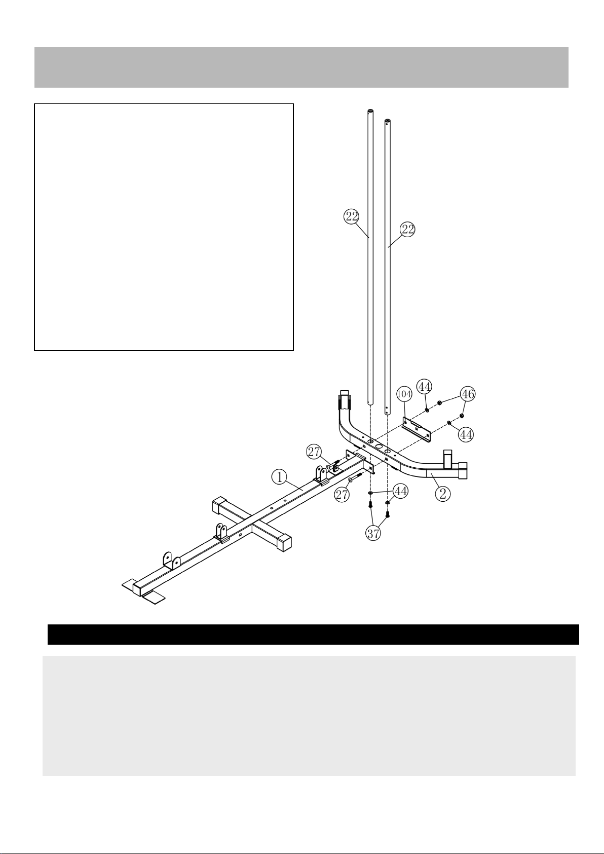
Assembly Instructions
1. Insert 2 pcs guide rods (22#) into the holes of the Rear Stabilizer(2#) separately and tighten them with
2 pcs M10*25 Allen Bolt(37#) and 2pcs Ø10 washers(44#).
2. Attach the Base Frame(1#) to the Rear Stabilizer(2#) as the diagram shows and tighten them with
2pcs M10*70 carriage bolt(27#),1pc bracket(104#),2pcs Ø10 washers(44#) and 2pcs M10 Aircraft
nuts(46#)
Step 1
Please download the latest electronic manual
from 【Product guides and documents】on the
product details page and watch the 3D installation
video tutorial from 【Videos for this product】.
Paper manuals are not guaranteed to be up to date
and there will be many installation details that
cannot be added.
The nut wrench and chain are included in a
plastic bag in box #2.
If any parts are missing, please contact the
seller.
Please be sure to regularly lubricate and
maintain areas where there is friction between
parts, for example steel cable and weight guide
#22 etc.
Happy Fitness.
7
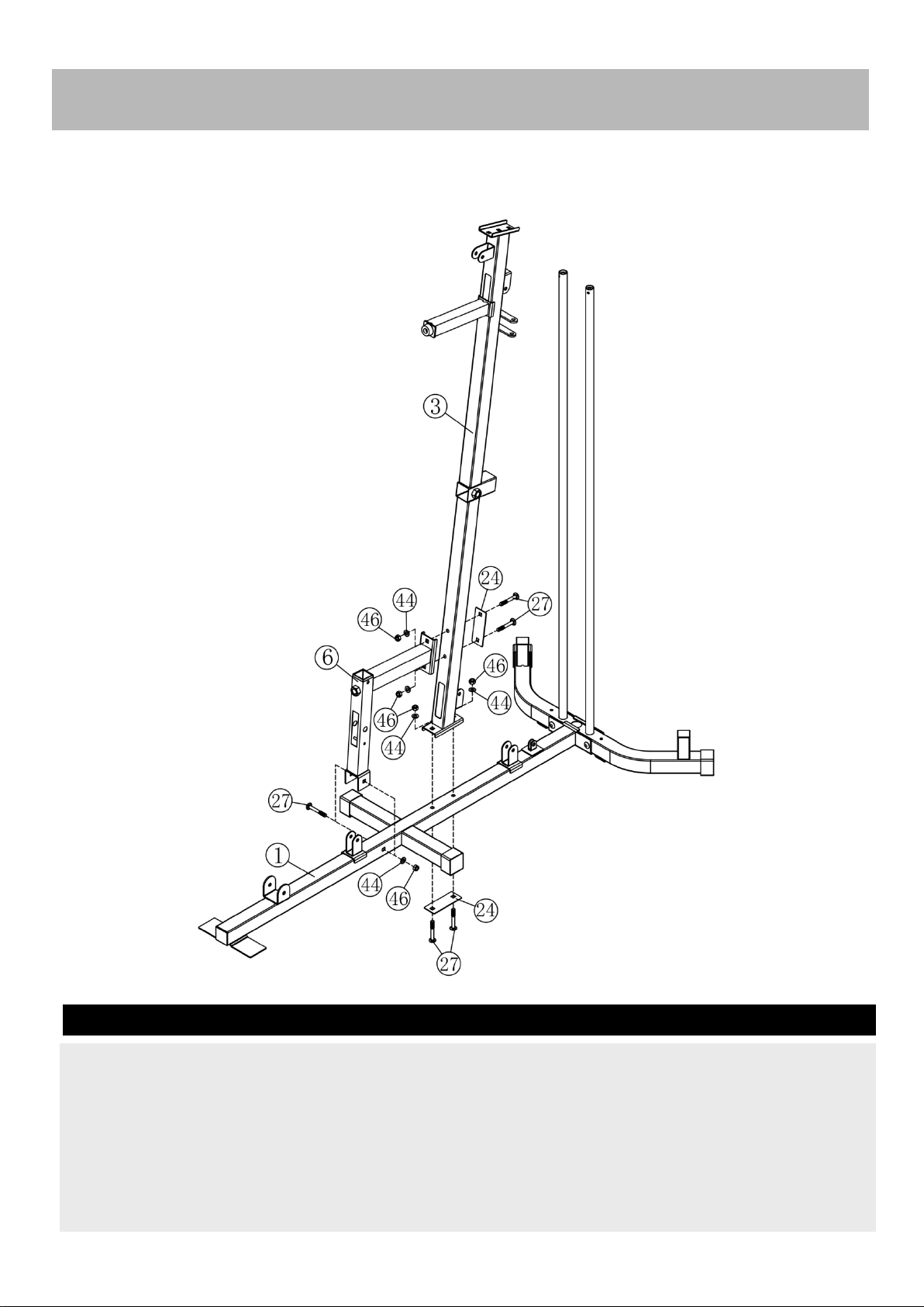
Step 2
Assembly Instructions
1. Attach the front vertical frame(3#) onto the base frame(1#). Carefully align the holes and secure
them with 2 pc M10*70 carriage bolt(27#), 1 pc bracket(24#),2pcs Ø10 washers(44#) and 2pcs M10
Aircraft nuts(46#) .
2. Attach the seat pad support(6#) to the front vertical frame(3#) and secure them with 2pcs M10*70
Carriage bolt(27#),1pc bracket(24#),2pcs Ø10 washers(44#),2pcs M10 Aircraft nuts(46#) .
3. Attach the seat pad support(6#) to he base frame(1#) and secure them with 1pc M10*70 Carriage
bolt(27#),,1pc Ø10 washer(44#), 1pc M10 Aircraft nut (46#) .

8
Assembly Instructions
Place the 2pcs weight plate bottom bracket(92#) along the guide rods(22#) and secure them with 2pcs
M10*25 Allen Bolt(37#) and 2pcs Ø10 washers(44#).
Place 14pcs weight plate(100#) along the guide rods(22#) from the top to the bottom, Insert the Selector
Rod(17#) into the center hole of the weight plates. And then place the weight stem(101#) again.
Step 3
Note:
#82 is a shock absorbing rubber pad.
#100 has the large U-shaped groove
facing down and the small U-shaped
groove facing up.
Note the distinction between #92 and
#91, there is no triangle inside #92.

9
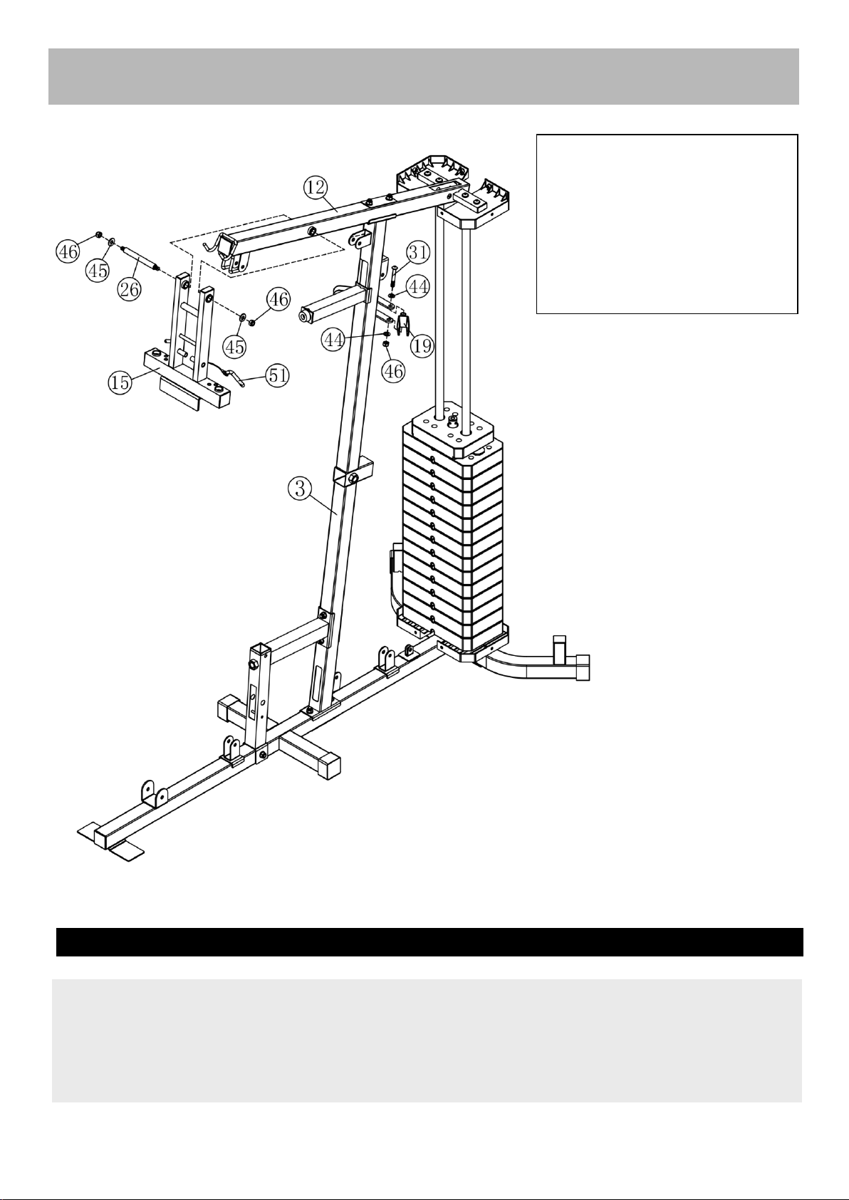
Assembly Instructions
1. Place the 2pcs weight plate upper bracket(91#) along the guide rod(22#).
2. Place the Upper Frame(12#) onto the Front Vertical Frame(3#) and 2pcs Guide Rod(22#), Align the
holes and secure them with 2pcs M10*25 Allen Bolt (37#),4pcs Ø10 washers(44#) ,2pcs M10*70
Carriage bolt(27#),1 pc bracket(24#),,2pcs M10 Aircraft nuts(46#) .
3.Attach the 2pcs weight plate upper bracket(91#) to the rear part of the upper frame with 2pcs M10*50
Allen Bolt (34#),2pcs Ø10 washers(44#).
Step 4
The area where #27 screws are installed
might be a little difficult to push #22
and loosen #3 screws (don't unscrew the
nuts completely) to finely adjust their
clearance distance, and finally tighten
them together.
Do not tighten #34 and #91 when
connecting them, just connect them a
little bit and let #91 lower the height as
much as possible. For the subsequent
installation of the protective cover more
easily.
10
Assembly Instructions
1. Attach the Front Press Frame(15#) to the Upper Frame(12#), Secure them with 1pcs axle(26#),2pcs
Ø25×Ø10.5×б1.5 washer(45#)and 2pcs M10 Aircraft nut (46#).
2. Attach the swivel pulley bracket(19#) to the support as the diagram shows, and secure it with 1pc
M10*65Allen Bolt (31#) ,2X Ø10 washer (44#) and 1pcM10 Aircraft nut (46#). Repeat the same way to
install another.
Step 5
Note:
All movable joints and the pulley
system behind require regular
grease maintenance. Improve user
comfort and parts life.
Do not tighten the nuts on both
sides of #26 and #19 too much.
Just let #15 and #19 turn flexibly.
11
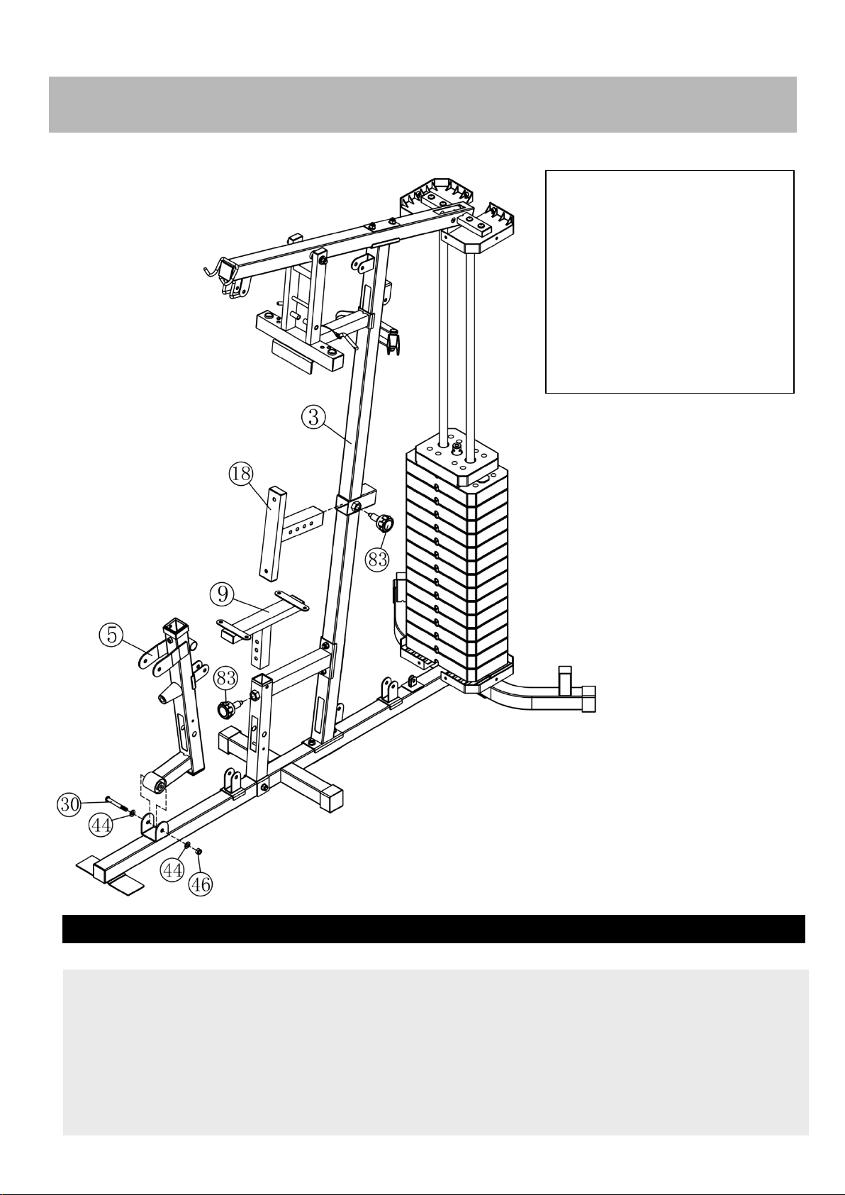
Assembly Instructions
1. Attach the Front support frame r(5#) onto the base frame, Secure them with 1pcs M10*80 Carriage
bolt(30#),2pcs Ø10 washers(44#),1 pc M10 Aircraft nuts(46#) .
2. Insert the seat pad adjustment support(9#) into the hole of the seat pad support, Select the desired
height with the lock knob(83#).
3. Insert the backrest pad support(18#) into the hole and select the desired location with theLock knob
(83#).
Step 6
Note:
When tightening #83, the
backrest or seat cushion can be
stabilized and not wobbling. and
when loosening, it can be pulled
and adjusted the position of the
backrest or seat cushion.
Do not tighten the nuts on both
sides of #5 too much. Just let #5
turn flexibly.

12
Assembly Instructions
Step 7
1. Attach the Right butterfly(8#) to the front press base,Secure them together with 1 pc Ø25×Ø10.5×б
1.5 Washer (45#),1pc M10 Aircraft nut(46#) .Push 1pc butterfly foam roll(78#) as the diagram shows.
2.Repeat the same way to install the left butterfly(7#).
3.Attach the leg developer(13#) as the diagram shows and secure them with swivel axle(25#),2pcs
M10*16 Allen bolt (38#) and 2pcs Ø10 washer (44#).
Do not tighten the nut bolts
connecting #7, #8 and #25 too
much. Allow them to turn
flexibly.
Hold the bottom of #78, turn it
left and right and push it
upward to install it on the arm.
Be careful not to block the
handle hole.
13
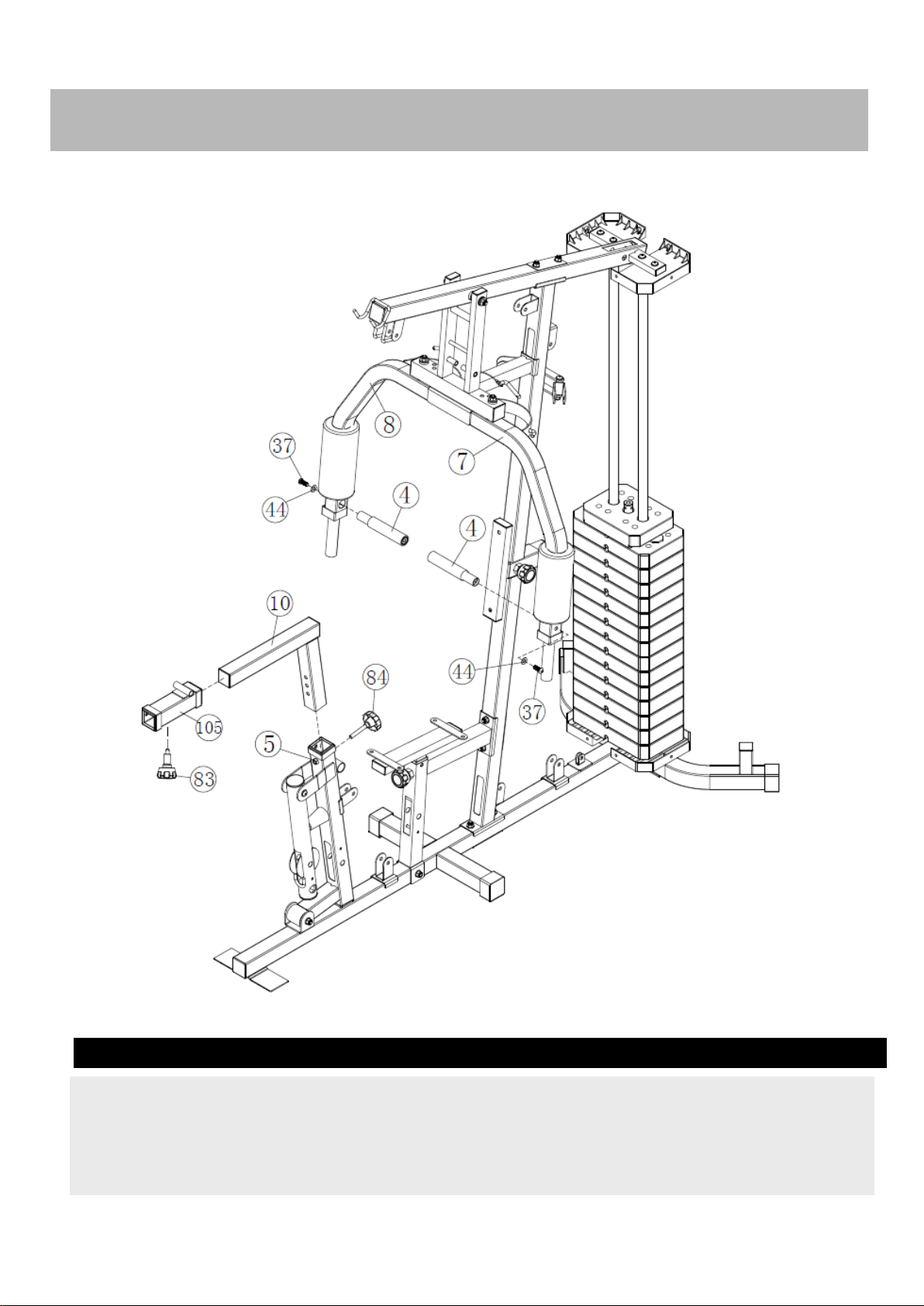
Step 8
Attach the 2pcs handle(4#) into the butterfly frame as the diagram shows. Secure them with 2pcs
M10*25 Allen bolt(37#) and 2pcs Ø10 washer (44#).
Insert the leg press frame(10#) into the hole as the diagram show and select the desired height with the
lock knob(84#).
Assembly Instructions
14
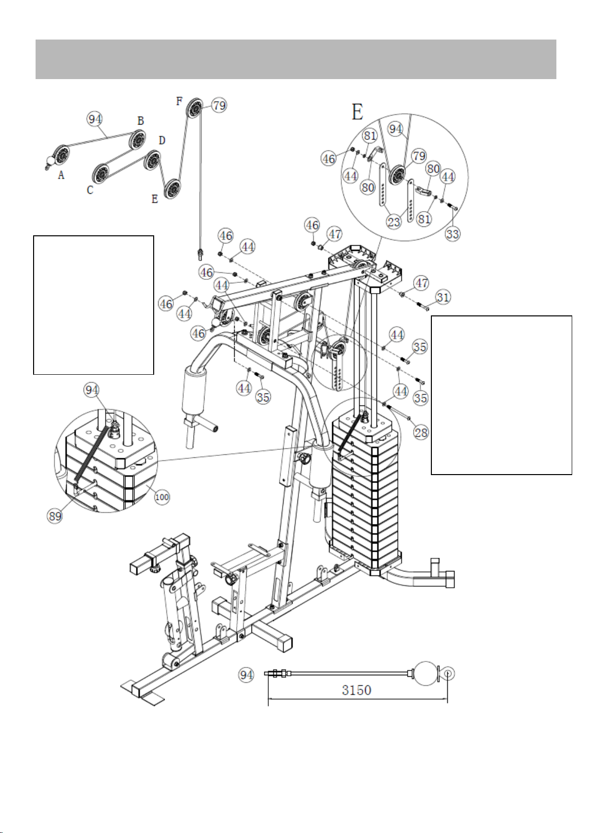
Assembly Instructions
Note:
#80 is optional, and
there is a chance that it
will rub against the skin
of the steel cable and
cause the skin to break.
There is a steel post on
the right side of pulley F.
Please do not let the
steel cable touch it.
Note:
Embed the steel
cables first, then
install the pulleys one
by one, and tighten
the screws in the
middle of the pulleys
appropriately. Pulley
needs to be flexible.

15
Step 9
A Feed the bolt end of the 3150mm Upper cable (94#) through opening in Upper frame . Place 1PC
Pulley (79#) below the cable and secure the 1st pulley using 1PCM10 ×45 Allen bolt (35#) ,2PC Ø10
washers(44#)and 1XM10 Aircraft nut (46#).
B Draw the cable backwards and place the 2st pulley below the cable , Secure the pulley with the same
way in A.
C Draw the cable around the pulley and front , Place the 3st pulley below the cable and secure them
with 1PC M10×140Allen bolt (28#), 2pcs Ø10 washers(44#),and 1 pc M10 Aircraft nut(46#).
DDraw the cable around the pulley and backwards,Place the 4st pulley below the cable and secure it
with the same way in A.
E Draw the cable around the pulley and downwards,Place the 5st pulley onto the cable, Secure the
pulley with double floating pulley bracket(23#) together with the 1pc M10*50 Allen Bolt(33#),2pcs Ø10
washers(44#),2 pcs bushing(81#), 2 pcs retainer(80#),and 1 pc M10 Aircraft nut(46#).
F Draw the cable around the pulley and upwards ,Place the 6st pulley below the cable and secure
them with 1PCM10*65 Allen bolt(31#), 2PC bushing(47#) and 1 pc M10 Aircraft nut(46#).
GDraw the cable around the pulley and downwards,thread the end of the upper cable to the top
opening of the selector rod at least 5 laps to keep safe.
Select the desired weight when exercising using the L shape Lock pin.
16
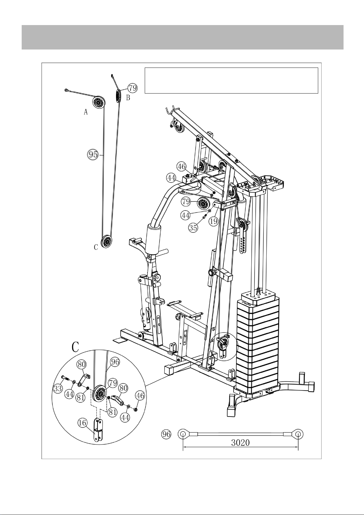
Assembly Instructions
!!! Note: If the direction of #19 is wrong, all cables
will be shortened, just turn to the correct direction.
Table of contents
Other SincMill Home Gym manuals

Popular Home Gym manuals by other brands


Inspire
Inspire CDVK2 Power Tower Assembly & operation manual

Hoist Fitness
Hoist Fitness H4400A owner's manual

Euroshine
Euroshine Euro Body Shaper user manual

Weider
Weider 325 Bench Bedienungsanleitung

Men'sHealth
Men'sHealth Active+ 490/9705 Assembly & user instructions

Weider
Weider Muscle 130 For Hermans Bench manual