Part list for Power Tower (CDVK2)
Part# Description Spec. Q'ty (pcs) Remark
1 Main Base 1
2 Main Upright 1
3L Left Leg 1
3R Right Leg 1
4L Left Support Arm 1
4R Right Support Arm 1
5 Cross Brace 1
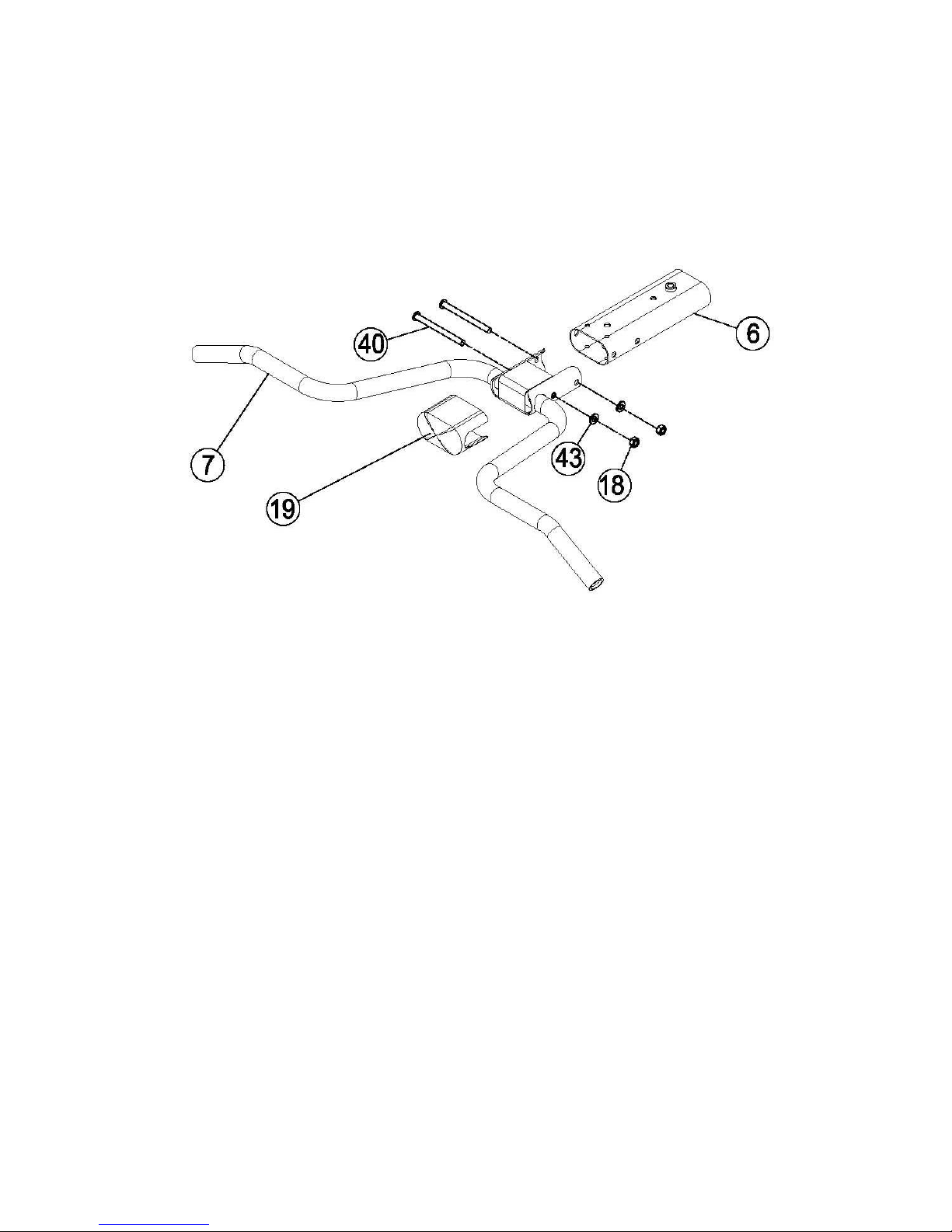
6 Top Beam 1
7 Lat Bar Assembly 1
8R Right Handlebar Assembly 1
8L Left Handlebar Assembly 1
9 Connector Plate 1
10 Arm Rest Cushion 2
11 Backrest Cushion Assembly 1
12 Backrest Cushion Hanging Plate 1
13 U Bracket 2
14 Backrest Cushion Protection Plate 1
15 Backrest Cushion Limit Plate 1
16L Push Up Tube (Left) 1
16R Push Up Tube (Right) 1
17 Steel Cable Assembly 1
18 End Cap 1 2
19 End Cover 1 BLACK
20 End Cap 2 Fit with100*50*2elliptical tube 1 BLACK
21 Rubber Plate 53*32*2 5 BLACK
22 Foot pad M10*30 3 BLACK
23 Rubber Cushion Fit with φ25.4 Round Tube 4 BLACK
24 End Cap 3 Fit φ25.4*2 Round tube 4 BLACK
25 Handlebar Grip 1 Φ33*Φ21*310 2 BLACK
26 End Cap 4 Fit with Φ50.8 round tube 2 BLACK
27 Handlebar Grip 2 Φ33*Φ21*150 2 BLACK
28 End Cap 5 Fit with 75*50*2 tube 3 BLACK
29 EVA Pad 100*25*2 4 BLACK
30 Push Up Tube Grip Φ33*Φ21*350 2 BLACK
31 Allen Head Screw M12 2 Black Zinc Plated
32 Allen Head Screw M10*105 3 Black Zinc Plated
33 Allen Head Screw M10*80 2 Black Zinc Plated
34 Carriage Bolts M8*40 4 Black Zinc Plated
35 Allen Head Screw M10*100 2 Black Zinc Plated
36 Allen Head Screw M10*20 6 Black Zinc Plated
PAGE 2