Sineoji PT308IP User manual

0
User Manual
Night Vision & Remote Operation for
Wireless Pan & Tilt IP Camera
Model: PT308IP, PT312IP, PT315V, PT324IP, PT325IP, PT331V
(Applicable for Windows XP, Windows Vista, Windows 7 and Windows 8)

1
Packing Contents
● Sineoji IP Camera
● User Manual
● Power Adapter
● Mounting Bracket
● Ethernet cable
● Software CD
● Mounting Bracket
1. Product Introduction
1.1 Safety Instructions
(1). Use the proper power source.
Do not use this product with a power source exceeding the specified voltage (100-240V AC).
(2). Never insert anything metallic into the camera.
Inserting metal object into the camera can be a source of dangerous electric shock.
(3). Do not operate in wet or dusty environment.
Avoid places like a damp basement or dusty hallway.
(4). Do not attempt to disassemble the camera.
You may be subjected to severe electrical shock if you attempt to take apart the camera while
the camera is connected to its power source. If there are any unusual sounds or smells coming
from the camera, unplug it immediately and contact the Customer Service.
(5). Handle the camera carefully
Dropping the camera on any hard surface may cause a malfunction. If the camera does not
work properly due to physical damage, please contact the Customer Service for repair or
exchange.
(6). Apply to FCC and CE Rule
This device complies with part 15 of the FCC and CE Rules. Operation is subject to the following
two conditions:
1: This device may not cause harmful interference.
2: This device must accept any interference received, including interference that may cause
undesired operation.
Any changes or modifications not expressly approved by the party responsible for compliance
could void the user’s authority to operate the equipment. This equipment complies with FCC
and CE radiation exposure limits set forth for uncontrolled environment. This equipment
should be installed and operated with minimum distance 20 cm between the radiator & your
body.
This transmitter must not be co-located or operating in conjunction with any other antenna or
transmitter.

2
1.2. Product Specifications
High sensor CMOS
Adopt optimized MJPEG video compression algorithm, realize high-definition images
transmission in narrow bandwidth;
Maximum support 4 users viewing at the same time, no limit for users if using forwarder
Server function
Built in Web Server, convenient for users to use standard browsing for
real time monitoring and setting administration;
Support WIFI:802.11 b/g/n wireless networking;
Support remote system update;
Support DDNS analysis, support LAN & Internet
Support variety of network protocol: TCP/IP, UDP, SMTP, PPPoE, Dynamic DNS,
DNS Client, SNTP, BOOTP, DHCP, FTP, SNMP, WIFI/802. 11b/g
Support one/ two way audio, talkback;
Support motion detection alarm function (area & sensitivity Configurable);
Support image snapshot
Abnormal automatic recovery function, auto reconnection available when network
Interruption occurred.
Dynamic alarm function, alarm time-schedule configurable.
1.3. System Requirements
CPU : 2.06GHZ or above
Memory : 265M or above
Network Card : 10/100/1000
Display Card : 64M or above
Operating System : Windows XP/Vista/Windows 7/Windows 8 (32 bit)
Internet Explorer : Version 5.0 or above
DirectX : Version 8.0 or above
Audio Card : Microphone and speaker output
Network Protocol : TCP/IP, UDP, SMTP, PPPoE, Dynamic DNS, DNS
Client, SNTP,BOOTP, FTP, SNMP, WiFi 802.11 b/g/n

3
1.4. Product Views
1.4.1 Front View

4
1.4.2 Rear View
Figure 1.2
Audio Out
LAN PORT: RJ-45 interface.
Antenna:
Power input interface: connect direct current 5V Power
TF Card Socket: Only applicable for models PT312IP, PT315V, PT325IP, PT331V

5
1.5 Hardware Installation
Follow the steps below to set up your camera hardware. Make sure to follow each step carefully
to ensure that the camera operates properly
1. Install the Wi-Fi antenna (For wireless model).
2. Plug the power adaptor into camera
3. Plug the network cable into camera, the other side to the router/switch
4. It takes approx. 30 seconds to boot up the camera, then you will find the IP address from
“Search Tool” (Figure: 1.8)
5. When the power is on and the network cable connected, the green led at the real panel will
be on; the yellow led will be blinking.
Figure 1.3
1.6 Software Installation
Figure 1.4
1. Browse the CD content and select “English”. Click on the “Search Tool”

6
2. Software operation
1.1 Search Tool Software
1.1.1 Search the IP address of the camera.
Double click the Icon “ ” run this IP address search tool.
Figure 2.1
Note: The software searches IP Servers automatically over LAN.
There are 2 scenarios:
1. No IP Cameras found within LAN. After about 1 minute search, the Cameras List Field does
not show the IP address.
2. IP Cameras have been installed within the LAN. All the IP Cameras will be listed and the total
number is displayed in the Cameras list field as shown in Figure 2.1
Note:
1. Current Computer indicates the Computer’s IP Address information.
2. Equipment information indicates the IP camera’s IP Address information.
3. If you find that the camera’s “Subnet Mask”, “Gateway”, “DNS Server” does not
correspond to your current computer’s values, you need try to change the camera’s IP
address.

7
Make sure the “Subnet Mask”, “Gateway”, “DNS Server” is the same as your router or your
current computer.
4. If you do not know how to configure your camera’s IP address. You can click “Update”
button. The Search Tool software will assist you to configure a usable IP camera automatically.
2.1.2 Configuration of the Network
Once your camera’s IP address’ Subnet Mask, Gateway, DNS Server is the same as your PC or
router, you need configure the camera’s Network parameter manually.
IP address: Fill in the IP address assigned and make sure it is in the same subnet as the
Gateway, and the subnet should be the same as your computer or router. (I.e. the first three
sections are the same)
Subnet Mask: The default subnet mask of the equipment is: 255.255.255.0. You can find the
subnet mask from your PC or router.
Gateway: Make sure it is in the same subnet with the PC’s IP address. The gateway is the LAN
IP of your router.
Primary DNS: IP address of ISP network provider. You can also set it as the same as the
Gateway.
NOTE: You can find out the Subnet Mask, Gateway, Primary DNS of your PC from the
“Search Tool” software.
Http Port: LAN port assigned for the equipment, default is 99. You can change the port
number to any one you want such as: 98,211,9999 etc.
3: Real-time Video Demonstration.
3.1. Camera Login:
You can access the camera through IP Camera Tool or IE, Firefox, Safari, Google Chrome or
other standard browser directly.
1. Double click the IP address of the IP Camera listed (Figure 2.1). The default browser you
use will run automatically and come to the camera login interface. (Figure 3.1)
2. To access the camera by IE Browser directly, just type the camera’s IP address, for
example, if the camera’s IP address is 192.168.1.99:99:

8
Figure 3.1
Username: admin
Password: NO PASSWORD.
Input the correct user name and password, the sign In interface will pop-up.
There are three modes to login (figure 3.2).
Figure 3.2
(1) ActiveX Mode (For IE Browser): available in IE6.0 or above explorer
(2) “RTSP Stream Mode”: available in Firefox, Safari, and Google browser.
(3) “No Plug-In Mode”: available in smart phone browser.
(4) SD card video playback online

9
3.2. View via IE Browser.
Select Active Mode (For IE Browser), and sign in.
The first time when you login to the camera, you may be prompted with an ActiveX script as
shown below. Please download the Ocx(or run in CD) and install, otherwise, the
camera’s live video will not appear.
Figure 3.3
Installing the Ocx-Setup (oPlayer Software), click ”NEXT” until it is completed.

10
Figure 3.4
Figure 3.3 Windows XP system
Note: If there is still no live video after running ActiveX, please try to enable the ActiveX options
of IE security settings, please do the follow steps:
1. Close the firewall of your computer.
2. Change the ActiveX settings, “IE” browser > “Tool” > “Internet Options” > “Security”>
“Custom Level” > “ActiveX control and Plug-ins”, all the ActiveX options set to be
“Enable”: Especially:
Enable: Download unsigned ActiveX controls
Enable: Initialize and script ActiveX controls not marked as safe
Enable: Run ActiveX controls and plug-ins

11
Figure 3.5
Figure 3.6
In Addition: you can also click “start” menu->“Internet Explorer”, choose “Internet attributes
“ to enter, or via “Control Panel” ->“Internet Explorer”, enter to Security setting.
3. If there is still no image, please close your anti-virus software, and then try step 1 & 2 again.

12
4. If the Active X is enabled, but yet with no live video with only a Red Cross in the
center of the video screen, check the device status light. If it is yellow instead of green,
please change the port number. Do not use port 80, enter other port such as99, 199 etc.
Figure 3.7
NOTE: Make sure that the firewall or anti-virus software does not block the software or ActiveX.
If you couldn’t see live video, please close your firewall or anti-virus software, and try again.
3.3. View via Safari, Firefox, Google Browser
Choose Server Push Mode (For Safari, Firefox, Google Browser), and sign in. Server Push Mode
doesn’t support ActiveX, so some functions are not available, such as Record, Audio, Talk,
Speaker, speed control bar, Zoom etc.),if you want to use these functions, please use IE
Browser.
13
The Control Interface in this mode is as bellow:
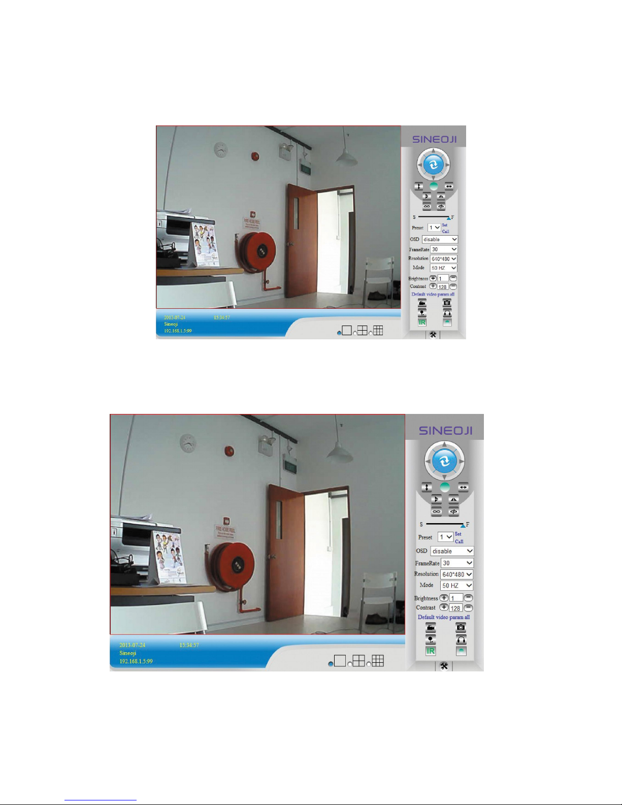
3.4. Main Menu interface introduction
Active Mode(For IE Browser)” Interface:
Figure 3.8

14
The Pan/Tilt Feature only works when the cameras have this Pan/Tilt function.
This option enables log detection. After the online user clicks on this button, a log is
entered into the camera’s Log Data documenting the IP address of the users who have
accessed the IP camera. This Option enables alarm detections too.
Vertical movement (for the Pan/Tilt Cams).
Left and right movement (for the Pan/Tilt Cams).
Flips the image vertically.
Flips the image horizontally.
Regulates the image frequency
Adjusts the image resolution, 720p resolution applicable for models
PT315V, PT331V
Regulate the speed of the Pan/Tilt
Preset of the camera. Only work for Pan/tilt Cams
Adjust the image brightness.
Adjust the image contrast.
This option resets all main menu options to factory default.
This option opens the camera’s recording functionality menu.
This option takes a snapshot of the current screen and saves the snapshot to the PC’s Hard
Drive.
This option enables User-to Camera audio.
This option enables Camera-to-User audio. If the online user has speakers connected and
configured to their PC, clicking this option will allow them to hear audio from the location of the
camera.
Display the time and date Turn ON/OFF IR LEDs
This button opens the IP camera’s Backend Menu

15
These options enable single view, quad screen view, or 9 screen view: This
function serves no purpose unless you have more than one camera connected and configured
to your interface.
* Please refer to section 8.1.1 Multi-Device Settings*
3.5. Administer Setting Instruction
When you login as an Administrator, you will have the Administrator privileges.
Administrator supports the necessary parameters and operations of the camera; you will gain
full control. There are some special functions designed for administrator privileges.
Alias setting : You can set your favorite device aliases.
Date &Time : Set the date and time.
User settings : Can be configured to a maximum of 8 users. On this page,
you can set up accounts such as user name, password, as well
as in their packet (administrator, operator, visitor).
Visitor : Visitor mode
Operator : You can configure the direction of the lens device, adjust
the video screen brightness, contrast and other parameters.
Administrator : You can adjust the device advanced configuration.
UPnP : If you want an internet access via the IPCAM, ensure that the
UPnP is enabled.
Device Firmware Upgrade: The system firmware updates the device firmware and
application.
Restore factory settings: Restore the factory defaults.
Reboot the device : Reboot the device.
Back : Return to monitor mode
3.5.1 Multi-Device Settings
Add a local area network equipment
In the multi-device configuration page, it reflects all the devices within the LAN. The first device
is the default camera. You can add more devices in the list. Embedded applications supports up
to 4 devices at the same time-line. Click the “second equipment” and double-click “Current list
of devices in the LAN” in the device entry name, host address. The Http port will automatically
be entered, user is required to enter the correct account name and password and click “Add.”
Repeat this procedure to add devices. Finally do not forget to click on the “Settings” button.

16
Figure 3.9
Figure 3.10

17
3.5.2 Network Settings
Figure 3.11
This sector is designed for DHCP and IP configuration and port forwarding. If you
manually assign an IP address, please fill in the respective IP address, subnet mask, gateway,
DNS server, Http port;
3.5.3 Wireless Settings
1. Ensure the router is a wireless router.
2. Make sure the Wi-Fi antenna installed.
3. Check if there is an encryption of the WLAN of the router.
4. Login to the camera, click >“Wireless Lan Settings”>”Scan”, you will find the
WLAN from the list, choose the SSID of your router.
5. If there is no encryption, just click “Submit”. If there is encryption, please enter the key,then
click “Submit”.
6. Wait about 30 seconds, the camera will reboot, and then unplug the network cable.

18
Figure 3.12
3.5.4 Dynamic DNS Setting (DDNS)
3.5.4.1 DDNS Setting:
(1): Click > “DDNS Service Settings”.
Figure 3.13
(2): Choose the DDNS; there are 4 kinds of options:
(1): Manufacturer’ DDNS: We provide a free DDNS: vipcam.org. This domain is provided by
manufacturer.
Note: If the DDNS Service is blank and should you wish to use the manufacturer’s free DDNS,
select “vipcam.org” and enter the DDNS User and DDNS Password which is located on the
bottom of your camera.

19
Figure 3.14
(2): The Third Party DDNS: This domain is provided by the 3rd party, such as Dyndns, Oray,
3322. If you use the third party DDNS, please choose the server you require, such as“3322.org”
or“ dyndns.org” as below:
Figure 3.15
This manual suits for next models
9
Table of contents
Other Sineoji IP Camera manuals


