From the library of Superior Sewing Machine & Supply LLC - www.supsew.com
8
MOVE TO
HIGHEST POINT
,.,,LOOSEN
SCREW
~
INSERT
NEEDLE
UP
FAR
AS
POSSIBLE
ND TIGHTEN SCREW
1 LONG
GROOVE
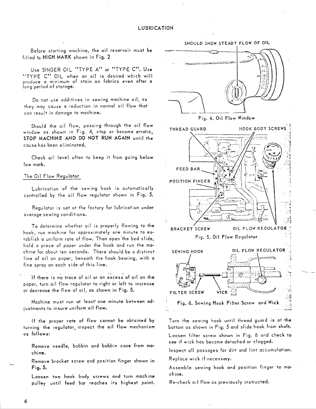
Fig.
9.
Machine
281-5
MOVE TO
HIGHEST POINT
LOOSEN SCREW
INSERT
NEEDLE
UP
AS FAR AS POSSIBLE
ND TIGHTEN SCREW
LONG.
~
I
GROOVE
2s,~so
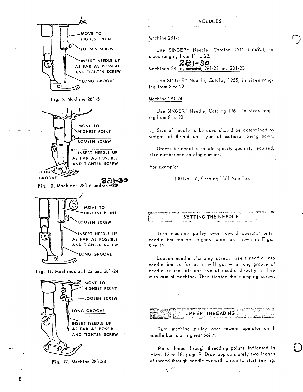
Fig.
10.
Machines
281-6
and
,z&mt,o
7d
MOVE
TO
~HIGHEST
POINT
.
'LOOSEN
SCREW
~INSERT
NEEDLE
UP
FAR AS POSSIBLE
ND TIGHTEN SCREW
1 LONG
GROOVE
Fig.
11.
Machines
281-22
and
281-24
MOVE
TO
HIGHEST
POINT
AS
FAR
AS POSSIBLE
AND
TIGHTEN
SCREW
Fig. 12. Machine 281-23
NEEDLES
Machine
281-5
Use
SINGER*
Needle,
Catalog
1515
(16x95),
in
sizes
ranging
from
11
to
22.
2e,-so
Machines
281-6,
.'.,,1-20,
281-22
and
281-23
Use
SINGER*
Needle,
Catalog
1955,
in
sizes
rang-
ing from 8
to
22.
Machine
281-24
Use
SINGER*
Needle,
Catalog
1361,
1n
sizes
rang-
ing from 8
to
22.
Size
of
needle
to
be
used
should
be
determined
by
weight
of
thread
and
type
of
material
being
sewn.
Orders
for
needles
should
specify
quantity
required,
size
number
and
catalog
number.
For
example:
100
No. 16,
Catalog
1361
Needles
~.~-,-,,""'"7'!!1"'1'P;-~~------._..,..,...
~.-·
,•~~---~-="'
~
•.
--.,-._"-~'-'-,-"
-:'II
i -
SETTING THE
NEEDLE
L,
..
~ ~
--~---...-
. --
--·~
-
....
Turn·
machine
pulley
over
toward
operator
until
needle
bar
reaches
highest
point
as
shown
in
Figs.
9
to
12.
Loosen
needle
clomping
screw.
Insert
needle
into
needle
bar
as
for
as
it
will
go,
with
long
groove
of
need
le
to
the
I
eft
and
eye
of
need
le
directly
in
Ii
ne
with
arm
of
machine.
Then
tighten
the
clomping
screw.
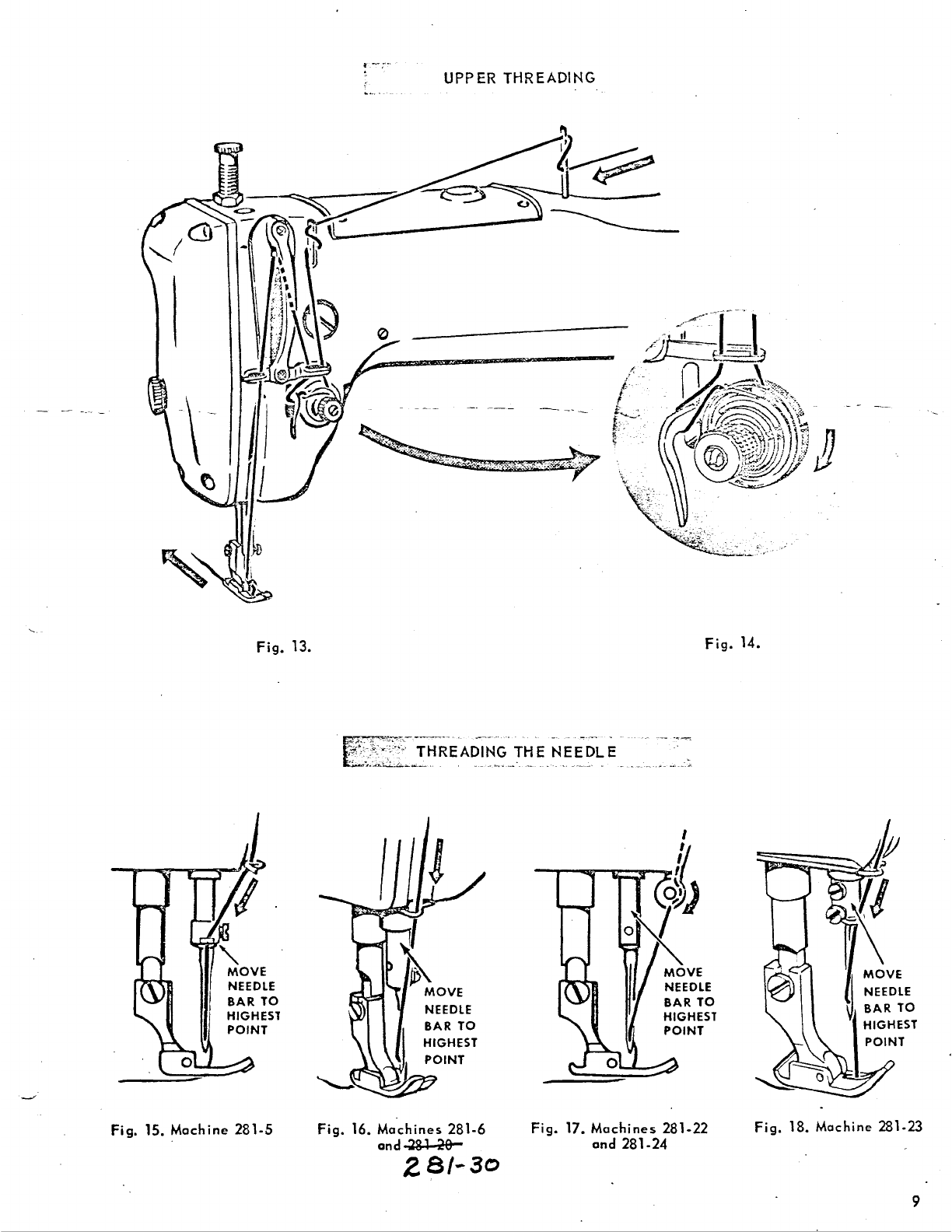
Turn
machine
.pulley
over
toward
operator
until
needle
bar
is
at
highest
point.
Poss
thread
through
threading
points
indicated
in
Figs.
13
to
18,
page
9.
Drow
approximately
two
inches
of
thread
through
needle
eyewith
which
to
start
sewing.
0