DESCRIPTION
The 457 G 1 machine is a high speed, single needle,
lock
stitch,
zig-zag sewing machine for stitching light
and medium weignt fabrics.
^
The
machine
specifications
are as
follows:
-
1.
Needle
Bar
Stroke
1-5/16
inch =
33.40
mm
Presser
Bar
Lift
9/32
inch
=
7.15
mm
Maximum
Width
of
Zig-Zag Stitch
5/32
inch = 4.00 mm
Space at right of Needle 8-3/16 inch = 208.00 mm
Maximum
Length
of
Stitch
6 stitches per
inch
= 4.20 mm per stitch
Bed 15-11/16 inches long, 7 inches wide
= 398.50 mm long, 177.80 mm wide
MachinePulley(SafetyType) for
3/8
inch= 9.50 mm
V-Belt.
Outside diameter of belt groove 2.9 inches
=
73.65
mm.
Effective
diameter
for
5/16
inch
=
7.93
mm
round
leather
belt
2-3/8
inches
=
60.30
mm.
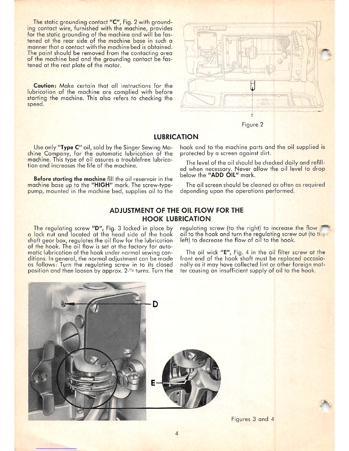
2. Automatic lubricating system for supplying oil to
all
moving
parts
which
can be observed through an
oil
flow
window
at
the
front
of
the
machine
arm.
3.
Transverse,
two
toone,
horizontal
axis
rotary
hook,
automatically pressure lubricated
and
with fine
ad
justment for the oil flow.
4. Single rotary take-up which controls thread at all
times to meet the requirements of the hook.
5. Thread pretension and rotary thread tension for
proper
regulation of the stitch formation.
6. Thewidth of the zig-zag
stitch
isset by turning the
bight control knob and the corresponding setting
is
indicated
at
the
front
of
the
machine.
7. The length of the
stitch
is
adjusted by changing the
feed driving eccentric on the bed shaft
and
the set
ting is indicated on the machine pulley.
8. Pendant
link
mechanism
with
eccentricfor adjusting
the feed dog to height and parallelism.
9. Low inertia presser
bar
mechanism.
10. The arm shaft, the needle vibrating shaft and the
belt
end
of
the
bed
shaft
are
mounted
in
double-
shielded ball bearings.
Needle bearings for the needle bar yoke connec
ting link
and
the feed driving eccentric connection;
super-oilite bushings for the feed driving eccentric
rockshaft, the needle bar yoke shaft and the needle
vibrating eccentric connection link.
11. The removable arm cover permits accessibility to
all parts in the arm.
12. Vibration absorbing location of the machine in the
machine base whioi is
firmly
mounted as oil pan
and
oil
reservoir
in
the
table.
SPEED
The maximum speed recommended for this machine
^
5000
R.P.M.
depending
on
materials
used
and
opera-
ons performed. It is
advisable
to run a new machine
-or a more moderate speed until an oil flow is visible in
the oil flow window and this speed should be maintain
ed for several minutes. When the machine is
In
operat
ion, the machine pulley must always turn over toward
the operator.
SETTING
UP
The machine rests on a cork gasket in the machine
base. The machine base also serves as drip pan, oil re
servoir and as housing for the knee lifter.
When using the SINGER-table the machine base rests
on
its
four cornersand
is
fastened by meansof rest
pins
(wooden) furnished
with
the machine.
Any
table-cut-out
into
which
the machine base cannot be inserted pro
perly must be reworked or adjusted by
shims
so that
the
machine
base
1.
does
not rock,
2. is level in both directions,
3. prevents the inserted machine from touching
the
table,
4. raises
the
inserted machine
above
the
table,
enough to open the bed slide
and
that the
bed hinge connections support the machine
only when it is tilted back.
When assembling the knee lifter make certain that
the knee lifter pin is properly inserted to connect the
knee
lifter
mechanism
of
the
machine
with
that
of
the
machine base. The lifting range of the knee lifting lever
sfc^n
be adjusted by the screw"A",
Fig.
1 (no
lifting)
and
^ the screw "B", Fig. 1
(full
lifting). When using the
~-itill
lifting range, the lifted presser
bar
lifter must disen
gage.
itufr'"-'
Figure 1