SINGFLO 2440 Series User manual

User Manual
SUBMERGED PUMP
ENGLISH

2
TABLE OF CONTENTS
PAGE(S)
INTRODUCTION 2
COMPONENTS NEEDED FOR INSTALLATION 2
PUMP CONNECTIONS & INSTALLATION INSTRUCTIONS 3-5
PARTS LIST and REPLACEMENT PART KITS 6
SUBMERSIBLE PUMP ASSEMBLY DRAWING 7
BEFORE REQUESTING SERVICE "Helpful Hints" 8
PUMP REMOVAL and DISASSEMBLY 9-10
PUMP RE-ASSEMBLY 11-13
APPLICATION WORKSHEET and FLOW CHARTS 14-15
TECHNICAL SPECIFICATIONS 16
TOOLS REQUIRED FOR INSTALLATION & MAINTENANCE 17
WARRANTY 18
INTRODUCTION
This manual has been provided as an aid to the operator with information about
installing, operating, and servicing of the SINGFLO 2440 Series Submersible Pump. The
engineers and technicians who designed and manufactured these pumps have developed
these instructions from their experiences.
These instructions should be read completely before installing your new pump. Keep this
manual readily available at all times for use when installing, operating, or servicing your pump.
For proper placement in the well refer to the application worksheet on pages 14-15.
This pump is not to be used with flammable liquids.
COMPONENTS NEEDED FOR INSTALLATION PAGE(S)
CABLE TYPE 3
COUPLERAND DISCHARGE FOR OUTLET 4
SAFETY LINE 5
POWER SUPPLY 15-16
FUSE: RECOMMENDED SIZE AND TYPE 16
TOOLS REQUIRED 17
CONTROLLER: Use of an LCB (Linear Current Booster) Unit is required for optimum performance.
COMPLETEAPPLICATION WORKSHEET 14-15

3
I. PUMP CONNECTIONS & INSTALLATION INSTRUCTIONS
WARNING: IMPROPER INSTALLATION WILL VOID WARRANTY.
1) Select proper jacketed cable size (Fig.1).
Note: DO NOT select cables with
irregular shapes, rough or
grooved surfaces.
Use a #10 AWG jacketed Submersible
cable that fits into the general size
requirements shown (Fig 1).
2) Assemble Cable Boot (Fig. 2, 3, 4).
a) Strip the outer cable jacket (Part A - not included) 2.0 in. (5 cm) (Fig. 2).
b) Cut one of the lead wires 1.0 in. (2.5 cm) (Fig. 3).
c) Wrap electrical tape around the cable. Start 2 in. (5 cm) below outer cable jacket
and continue to taper a point past the end of lead wires (Fig. 4).
Generously lubricate the cable 4 to 6 in. (10 to 15 cm) with supplied O-Ring grease.
d) Slide the cable boot components over the cable (Part A) in the following order (Fig. 4).
1) Nut (Part D). Make sure threads are toward pump end of cable.
2) Outer Cable Boot (Part C). Small end first.
NOTE: Re-lubricate cable as necessary.
3) Inner Cable Boot (Part B). Small end first.
e) Remove tape and cut the lead wires back leaving about .50 in. (1.3 cm) exposed.
Strip the inner conductor jacket .50 in. (1.3 cm) (Fig. 5).
(8 .0 m m )
.3 2 IN
(1 4 .5 m m )
.5 8 IN
(1 0 .5 m m )
.4 2 IN
(5 .5 m m )
.2 2 IN
(1 1 .5 m m )
.4 5 IN
(9 .0 m m )
.3 5 IN
FIG U R E 1
FLAT
ROUND
PARALLEL
RECOMMENDED
CABLE TYPE
MINIMUM
DIMENSION OF CABLE MAXIMUM
DIMENSION OF CABLE
(5 C M )
2 .0
FIG U R E 2
A
FIG U R E 3
1 .0
(2 .5 C M )

4
f) Insert the wire leads into Plug (Cable Adapter) connectors.
Using a 5/64" Allen Wrench tighten the set screws (Fig. 6).
g) Slide the Inner Cable Boot (Part B) over the plug until it is flush with
the first step on the collar (Fig. 6).
Wipe the grease from the surface of Inner Cable Boot and cable.
Tape end of Inner Cable Boot tightly to the cable.
Be sure to tape 4 in. (10 cm) below the Inner Cable Boot on the cable.
Note: This taped area allows the Outer Cable Boot (Part C) to slide freely over the Inner Cable Boot.
DO NOT REMOVETHETAPE.
h) Lubricate the outer surface of the Inner Cable Boot and tape with supplied O-Ring grease.
Slide the Outer Cable Boot (Part C) over the Inner Cable Boot until it is flush with
the second step on the collar (Fig. 6).
i) Push the Plug (Cable Adapter) into the Receptacle (Cable Adapter) until the collar is seated flush.
NOTE: The orientation of the Plug(Cable Adapter) will not effect the pumps performance.
j) Push the Nut (Part D) over the Plug (Cable Adapter) and then finger tighten the nut.
NOTE: Before continuing, operate the pump to check all electrical connections,
using the correct power supply. Refer to Technical Specifications (Pg. 14).
If pump does not operate Refer to "Helpful Hints" (Page 8) before continuing .
3) Install the 6 in. hose and fitting (1/2" NPT X 1/2" BARB) (Fig. 7, page 5).
a) Press the fitting into the 6 in. hose, slide the clamp on the hose and over the fitting and tighten the clamp securely.
b) Slide another clamp on the 6 in. hose, slide the assembly over the barbed fitting on the pump,
and tighten the clamp securely.
Note: Select the proper adapter hose and accessories for the pump.
USE OF DISCHARGE PIPE LARGER THAN 3/4" IS NOT RECOMMENDED..
Use 150 P.S.I. Min. (10 bars) working pressure rated 1/2 in. I.D. (12.7 mm I.D.) smooth bore hose (Part not included.).
Use All-Stainless Steel hose clamp (Part not included.
1 /2 " N P
T
5
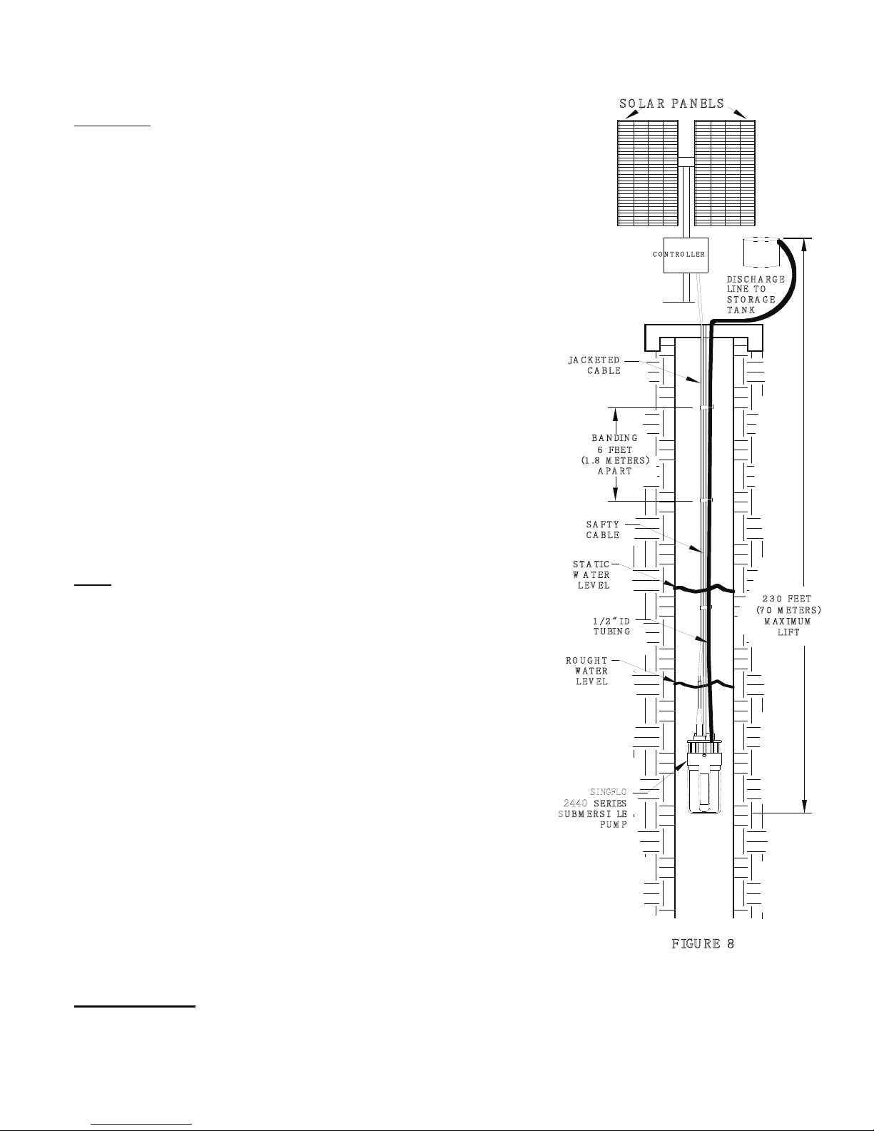
4) Hook-up Safety Line (Sling) (Fig. 7).
CAUTION: Safety line (Sling) should be
Corrosion resistant.
a) Insert safety line (Part not included) through
lift plate holes.
b) Fasten line with appropriate connection
approximately 1-2 ft (30 - 60 cm) above the pump.
5) Band the Hose, Safety Line, and Electrical
Cable (Fig. 8).
Tie the drop lines together using tie wraps
every 6ft. (1.8 m).
This banding will prevent unnecessary damage to the
lines during Installation and Removal of pump.
6) Install Pump (Fig. 8).
Note: Prior to installing the pump, fill in the application worksheet
on pages 14-15.
The application worksheet is a guide to make sure that the pump is
installed properly in the well.
Following the guidelines laid out in the application worksheet will
allow the pump to perform efficiently and extend the life of the unit.
Refer to "Helpful Hints" if you experience any difficulties.
PARTS LIST
LIFT
M A X IM U M
(7 0 M ET E R S )
2 3 0 FEET
(1 .8 M E T E R S )
A P A R T
6 FEET
B A N DIN G
C A B L E
JA C K E T ED
S U B M E R S IBLE
S E RIES
LEV EL
W A T E R
D R O U G H T
T U BIN G
LEV EL
W A T E R
S T A TIC
C A B L E
S A FT Y
T A N K
S T O R A G E
LIN E T O
SO L A R PA N ELS
2440
1 /2 " ID
FIGU RE 8
DIS C H A R G E
PU M P
C O N T RO L L ER
SINGFLO

6
ITEM DESCRIPTION QUANTITY
A CABLE [NOT INCLUDED] 1
B INNER CABLE BOOT 1
C OUTER CABLE BOOT 1
- PLUG (CABLEADAPTER) [NOT SHOWN]1
- SCREW (PLUG) [NOT SHOWN]2
D NUT 1
E SCREW (LIFT PLATE) 6
F LIFT PLATE 1
G OUTLET FITTING 1
H O-RING (OUTLET FITTING) 1
I O-RING (LIFT PLATE) 3
J RECEPTACLE (CABLEADAPTER) 1
K SET SCREW (RECEPTACLE) 2
L SCREW (MOTOR) 3
M FILTER SCREEN 1
N UPPER HOUSING 1
O O-RING (UPPER HOUSING) 2
P SPRING (BYPASS) 3
Q POPPET (BYPASS) 3
R VALVE HOUSING ASSEMBLY 1
S LOWERHOUSING ASSEMBLY 1
T MOTOR 1
U CANISTER 1
V SCREW (CANISTER) 3
W LOCK WASHER (MOTOR SCREW) 3
REPLACEMENT PART KITS
24-135-00 LIFT PLATE *[E,F,I]
24-136-00 CABLEPLUG KIT *[B,C,D,J,K,PLUG(CABLE ADAPTER) W/ SET SCREWS]
24-137-00 VALVE ASSEMBLY KIT *[O,P,Q,R]
24-138-00 LOWERHOUSING ASSEMBLY KIT *[O,S]
24-139-00 MOTOR KIT *[O,T]
24-140-00 CANISTER KIT *[O,U,V]
24-141-00 FILTER SCREEN KIT *[M]
24-142-00 O-RING KIT *[H,I,O,O-RING(VALVEHOUSING ASSEMBLY)]
24-143-00 TOOL KIT *[5/64", 5/32" and 3/16" ALLEN WRENCHES, #1 and #2 PHILLIPS SCREWDRIVERS]
*[ ] DENOTES PARTS INCLUDED IN KITS.

7
V
WEIV B I
U
T
S
R
Q
P
O
N
M
L
K
J
I
G
F
E
D
C
B
A
W
F
H
R
Q
VIEW A
P
1
2
34
5
6
7
8
1 2 3 4 5 6 7 8
Lift Plate Cable Plug Valve Lower
Housing Motor Canister Filter
Screen O-Ring
24-135-00 24-136-00 24-137-00 24-138-00 24-139-00 24-140-00 24-141-00 24-142-00

8
BEFORE REQUESTING SERVICE
"Helpful Hints"
SYMPTOM PROBABLE CAUSE CORRECTION
PUMP OPERATES but: 1) LOW VOLTAGE 1) CHECK POWER SUPPLY FOR PROPER VOLTAGE.
NO FLOW or REFER TO TECHNICAL SPECIFICATIONS (Pg. 16).
REDUCED FLOW
2) NO WATER AT PUMP 2) MAKE SURE THE PUMP IS INSTALLED
BELOW THE LOWEST ANTICIPATED
WATER LEVEL.
REFER TO INSTALLATION SECTION (Pg. 5).
3) PUMP LOCATED 3) REFER TO INSTALLATION SECTION (Pg. 5)
TOO DEEP FOR PUMP OPERATING RANGE.
4) CLOGGED FILTER 4) REMOVE FILTER SCREEN AND RINSE.
SCREEN REFER TO REMOVAL AND
DISASSEMBLY SECTION (Pg. 9).
5) FLUID PATH IN 5) CHECK FOR PINCHED HOSE, CLOGGED
PLUMBING RESTRICTED LINES.
6) LOOSECONNECTIONS 6) CHECK HOSE CLAMPS or REPLACE HOSE (Pg. 4).
or PUNCTURED HOSE.
PUMP WILL 1) INCORRECT POWER SUPPLY 1) CHECK POWER SUPPLY.
NOT OPERATE: REFER TO PUMP TECHNICAL SPECIFICATIONS
(Pg. 16).
2) WIRE CONNECTIONS 2a) CHECK ELECTRICAL CONNECTIONS ON
SYSTEM.
2b) CHECK THE PLUG(CABLE ADAPTER)
ELECTRICAL CONNECTION MADE
DURING THE INSTALLATION IS NOT
CORRODED OR LOOSE.
REFER TO CABLE BOOT INSTALLATION
INSTRUCTIONS FOR DISASSEMBLY
AND REASSEMBLY(Pg. 3-4).
2c) CHECK FOR BLOWN FUSES IN-LINE.
CONTACTAN AUTHORIZED DISTRIBUTOR FOR FURTHER ASSISTANCE.
9
II. PUMP REMOVAL AND DISASSEMBLY
For servicing using Replacement Part Kits.
Warning: Make sure all electrical power is off and the Hose (Pipe) is
not under pressure.
Warning: Canister maybe pressurized, disassemble the pump in proper order.
Follow the manual directions carefully.
Note: Keep all of the parts clean after disassembly.
Upper Housing Assembly contains small parts.
Be careful not to lose parts after removing Upper Housing (Part N) step 9.
1) Remove the Pump from the well.
To prevent damaging the Electrical Connection during removal from well
DO NOT PUT STRESS ON THE ELECTRICAL CORD.
2) Disconnect the Hose.
Remove the Hose clamp, pull and twist the hose to remove it
from the fitting.
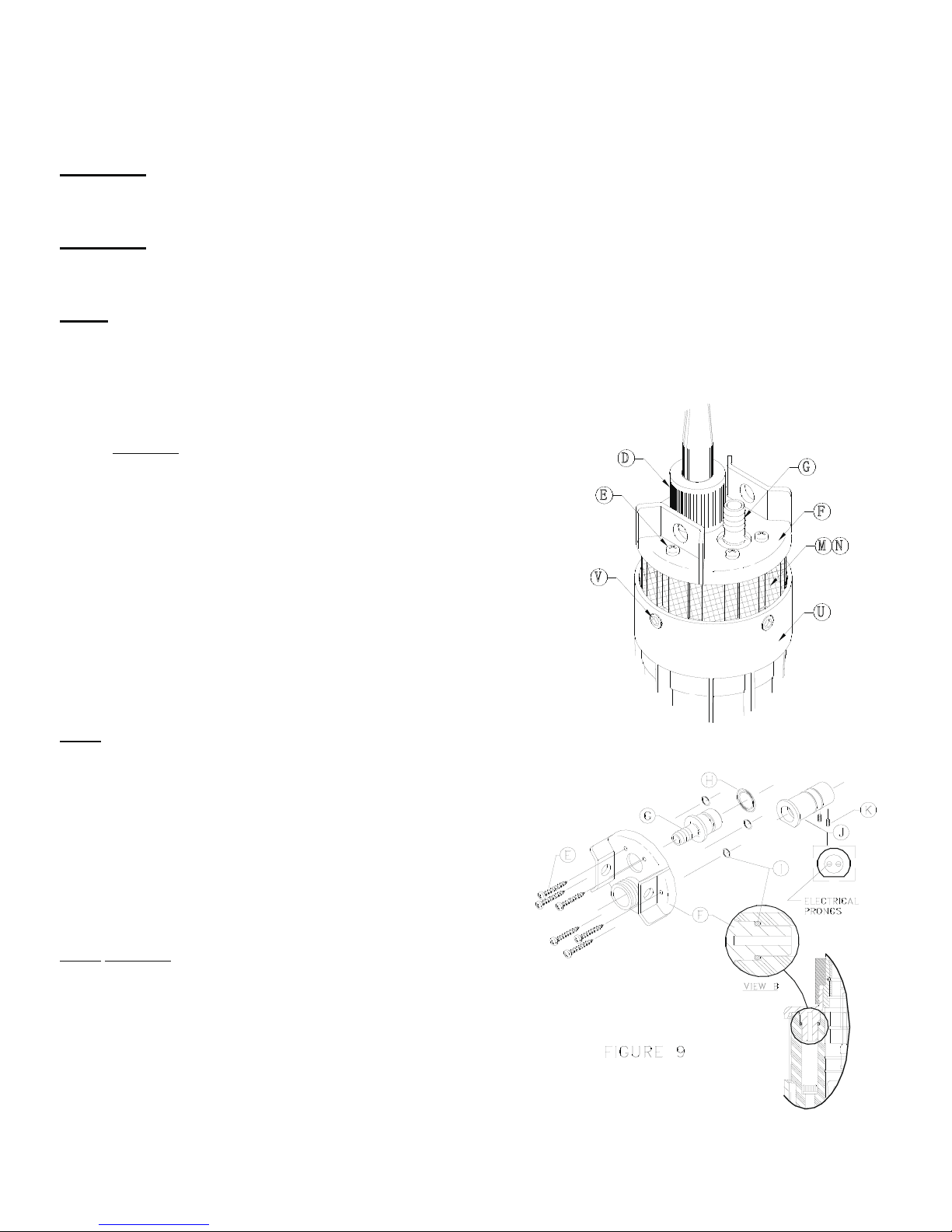
3) Unplug the Cable Adapter Assembly (Fig 9).
Remove the Nut (Part D) unscrewing it counterclockwise and
pull the plug up.
4) Remove the Lift Plate (Part F) (Fig. 9).
Using a #2 Phillips Screwdriver remove the screws (Part E) from 6 places
and pull up the Lift Plate.
Note: Be sure to put the O-Rings (Part I) back on
the Lift Plate Posts (Fig. 9, View B) before continuing to step 5.
If necessary, the filter screen may be removed for
cleaning at this stage of the disassembly.
5) Remove the Outlet Fitting (Part G) (Fig. 9).
Remove the fitting from the Upper Housing (Part N) by
pulling it straight out.
6) Remove the Receptacle (Cable Adapter) (Part J) (Fig. 9).
Note: DO NOT PULL ON THE ELECTRICAL PRONGS.
a) Using pliers carefully pull up on the shoulder of the
Receptacle (Cable Adapter) and pull it completely out
of the Upper Housing (Part N).
b) Using a 5/64" Allen Wrench, loosen the screws
holding the motor leads (Part k) from 2 places and
disconnect the Receptacle (Cable Adapter).
V
E
DG
F
M
U
N
10
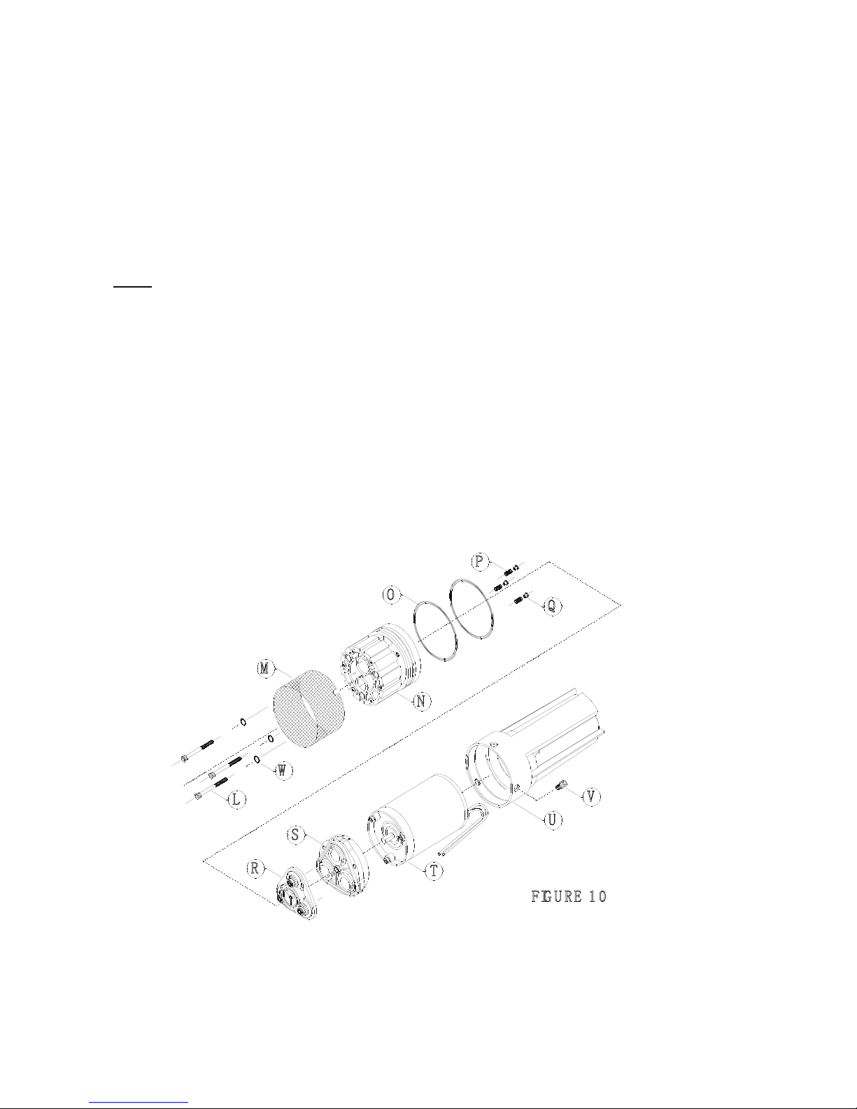
7) Slide off the Filter Screen (Part M) (Fig. 10).
8) Remove the Canister (Part U) (Fig. 10).
a) Using a 3/16" Allen Wrench remove the screws (Part V) from 3 places.
b) Place one hand on the Upper Housing and the other on the Canister. Twist and pull the Assembly apart.
9) Remove Upper Housing (Part N) and Motor (Part T) (Fig. 10).
Note: Keep all parts clean after disassembly.
The Upper Housing Assembly contains small parts.
Be careful not to lose parts after removing Upper Housing.
a) Using a 5/32" Allen Wrench remove the screws (Part L) from 3 places.
b) Before separating the Upper Housing from the Motor, place the assembly on the Upper Housing(Down)
and the Motor facing up.
c) Separate the Upper Housing, Valve Housing and Lower Housing Assembly (Parts R, S), Poppets (Part Q),
and Springs (Part P).
10) Contact an authorized distributor for assistance with diagnosis and
replacement Parts (Refer to page 6 for replacement part kit list).
FIG U R E 1 0
L
N
O
P
Q
R
S
T
U
V
W
M
11
III. PUMP RE-ASSEMBLY
Warning: The order of Assembly is important to ensure proper sealing.
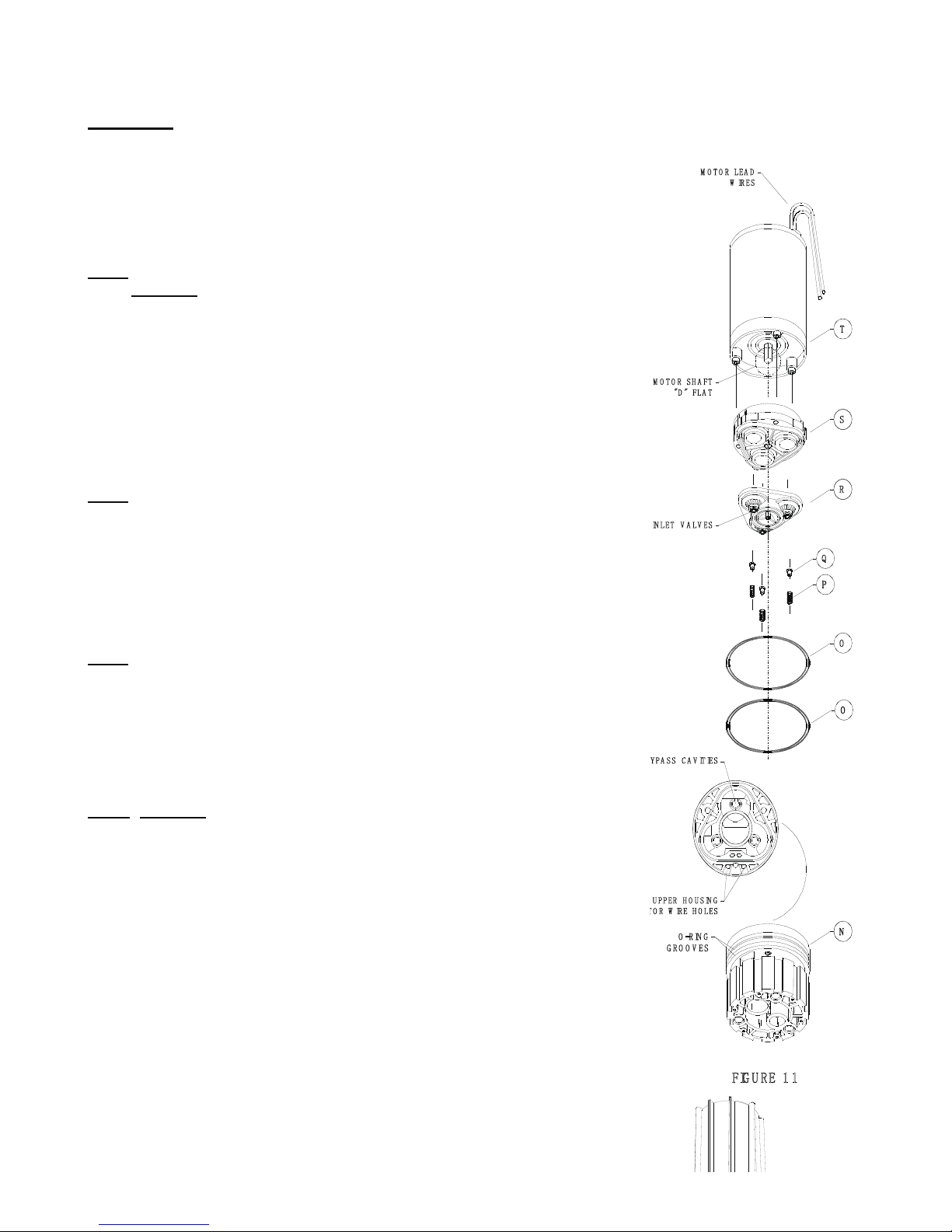
1) Install the Upper Housing Large O-Rings (Part O) (Fig. 11).
a) Remove the existing Large O-Rings and thoroughly clean the
O-Ring grooves with a dry cloth and a cotton tipped applicator.
Note: Lubricate the O-Rings with the Supplied O-Ring Grease.
DO NOT USE PETROLEUM BASED LUBRICANT.
b) Slide the two new Large O-Rings over the Upper Housing (Part N) and
into the O-Ring grooves.
c) Place the Upper Housing down with the internal cavities exposed.
Turn the Upper Housing until the motor wire holes are directly in front.
2) Install the Bypass Assembly (Parts P and Q) (Fig. 11).
a) Place the Poppets (Part Q) into the Springs (Part P).
Note: Make sure that the Poppets are seated flush against the Springs.
b) Locate the three bypass cavities and place the Spring/Poppet Assembly
into the cavities with the Poppet up.
3) Install the Valve Housing Assembly (Parts R) (Fig. 11).
Place the Valve Housing Assembly into the Upper Housing (Part N).
Note: Make sure that the inlet valves are centered on top of the bypass
Poppets (Part Q).
4) Install the Lower Housing Assembly (Part S) (Fig. 11).
a) Place the Lower Housing Assembly onto the
Valve Housing Assembly (Part R) (Fig. 11).
Note: DO NOT FORCE THE ASSEMBLY.
IT SHOULD SNAP TOGETHER EASILY IN
ORDER TO SEAL PROPERLY.
5) Install the Motor (Part T) (Fig. 11).
a) Lubricate the motor shaft with a small amount of general purpose grease.
b) Align the "D" flat of the motor shaft with the "D" flat on the
Lower Housing Assembly (Part R).
c) Align the motor lead wires with the Upper Housing (Part N) wire holes.
Align the three tabs on the motor with the holes on the
Lower Housing Assembly (Parts R) and set the motor onto the Lower
Housing.
d) Insert the motor lead wires into the Upper Housing motor wire holes.
Push the wires until they touch the surface that the Upper Housing is resting on.
O -R IN G
G R O O V E S
O
N
"D " FL A T
M O T O R S H A FT
P
Q
T
O
R
S
M O T O R L EA D
W IR E S
FIG U R E 1 1
IN LET V A L V ES
U P P ER H O U S IN G
T
O R W IRE H O LE S
Y P A S S C A V IT IES
12
6) Install the Canister (Part U) (Fig. 12).
a) Clean the inside of the Canister with a dry cloth.
b) Align the wire channel in the canister with the motor lead wires.
c) Slide the canister over the entire assembly .
d) Twist the canister to align the screw holes and carefully press on
end to seat properly.
7) Install the Screws (Part V) (Fig. 12).
Note: DO NOT USE MORE THAN15 (±5) in lb [1.7 Nm (±.5)] torque
TO PREVENT STRIPPING.
Using a 3/16" Allen Wrench tighten the screws in 3 places into
the Upper Housing (Part N).
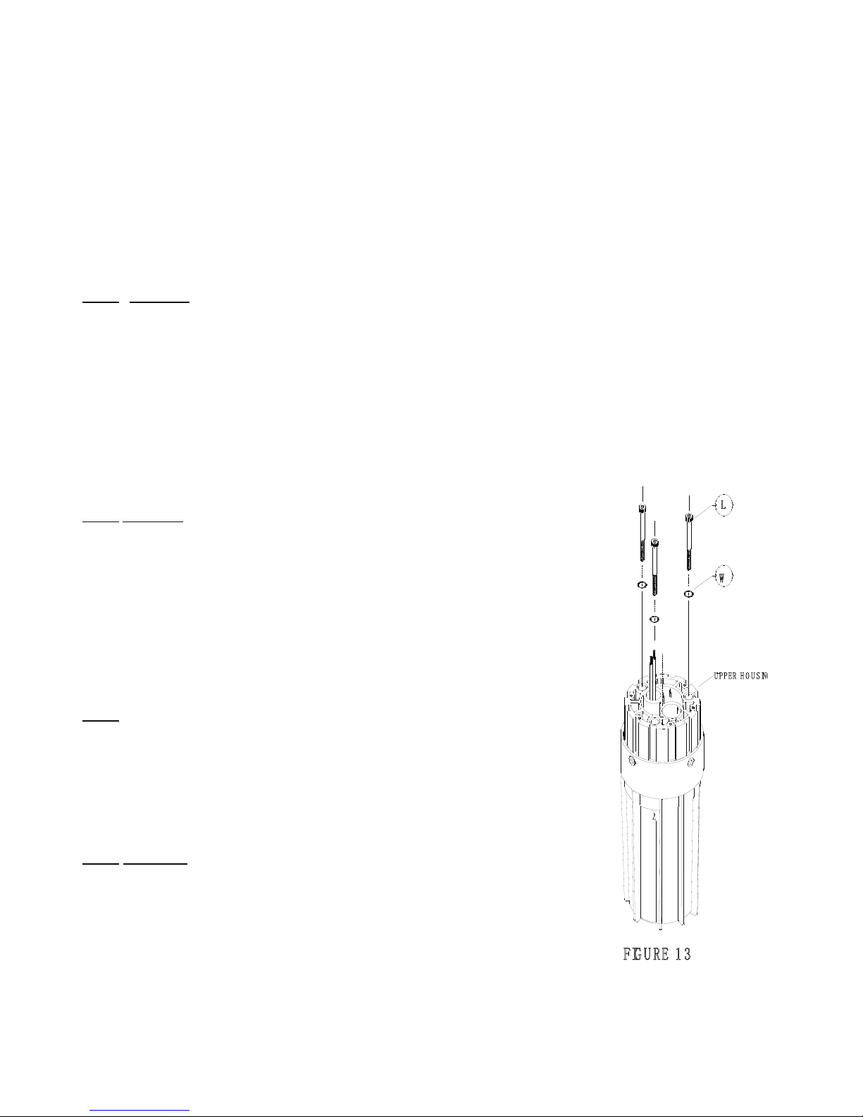
8) Turn the assembly over as shown in Figure 13.
9) Install the Lock Washers (Part W) and Screws (Part L) (Fig. 13).
a) Slide the three Lock Washers onto the screws and place the screws
in 3 places into the Upper Housing (Part N).
Note: DO NOT COMPLETELY TIGHTEN ONE SCREW AT A TIME.
TIGHTEN THE SCREWS WITH TWO PASSES
SLOWLY COMPRESSING THE ASSEMBLY TOGETHER.
b) Using a 5/32" Allen Wrench tighten the screws on the first pass
with 25 (±5) in lb [2.8 Nm (±.5)] torque.
c) Tighten the screws on the second pass
with 65 (±5) in lb [7.3 Nm (±.5)] torque.
10) Connect the Receptacle (Cable Adapter) (Part J) (Fig. 14, page 13).
Note: The orientation of the motor lead wires will not effect the pumps
performance.
a) Pull the motor lead wires up through the Upper Housing (Part N) and insert
them into the Receptacle (Cable Adapter).
b) Using a 5/64" Allen Wrench hand tighten the screws on the
Receptacle (Cable Adapter) for both wires.
Note: DO NOT TIGHTEN WITH A POWER TOOL.
c) Lubricate the outer surface of the Receptacle (Cable Adapter) with the
Supplied O-Ring grease.
d) Match the flat side of the Receptacle (Cable Adapter) with the flat side
of the hole in the Upper Housing.
e) Push the Receptacle (Cable Adapter) into the hole in the Upper Housing
until it is seated flush.
f) Spread each Receptacle (Cable Adapter) electrical prong slightly to insure the electrical connection.
W
L
FIG U RE 1 3
U PPER H O U S IN

13
11) Install the Filter Screen (Part M) (Fig. 15).
a) Slide the Filter Screen onto the Upper Housing (Part N).
b) Align the slots in the Filter Screen with the screws (Part V) in the Upper Housing and
slide the Filter Screen over the screws.
12) Install the Outlet Fitting (Part G) (Fig. 15).
a) Lubricate the O-Ring (Part H) and slide it into the O-Ring groove
on the Outlet Fitting.
b) Push the Outlet Fitting into the hole in the Upper Housing (Part N).
13) Install the Lift Plate (Part F) with three the O-Rings (Part I)
on the posts (Fig. 15).
a) Align the three posts with the Upper Housing (Part N) screw holes and
press on the Lift Plate until it is flush against the Upper Housing.
Note: DO NOT USE MORE THAN20 (±5) in lb [2.25 Nm (±.5)] TORQUE
TO PREVENT STRIPPING .
b) Using a #2 Phillips Screwdriver install the screws (Part E) 6 places
into the Lift Plate.
14) Install the Plug (Cable Adapter) Assembly.
Note: The orientation of the Plug(Cable Adapter) will not effect
the pumps performance.
Note: IF IT BECOMES NECESSARY TO REASSEMBLE
THE PLUG (CABLE ADAPTER) ASSEMBLY, REFER
TO PUMP CONNECTIONS & INSTALLATION INSTRUCTIONS (Pg. 3-
5).
a) Align the Plug (Cable Adapter) connector holes with the electrical prongs
in the Receptacle (Cable Adapter).
b) Push the Plug (Cable Adapter) into the Receptacle (Cable Adapter)
until the collar is seated flush.
c) Push the Nut (Part D) over the Plug (Cable Adapter) and finger tighten the nut.
Note: Before placing the pump back into the well, operate
the pump to check all electrical connections using the
correct power supply.
Refer to Technical Specifications (Pg. 14).
FIG U R E 1 5
I
E
F
G
H
U P P E R H O U S IN G
M
V
14
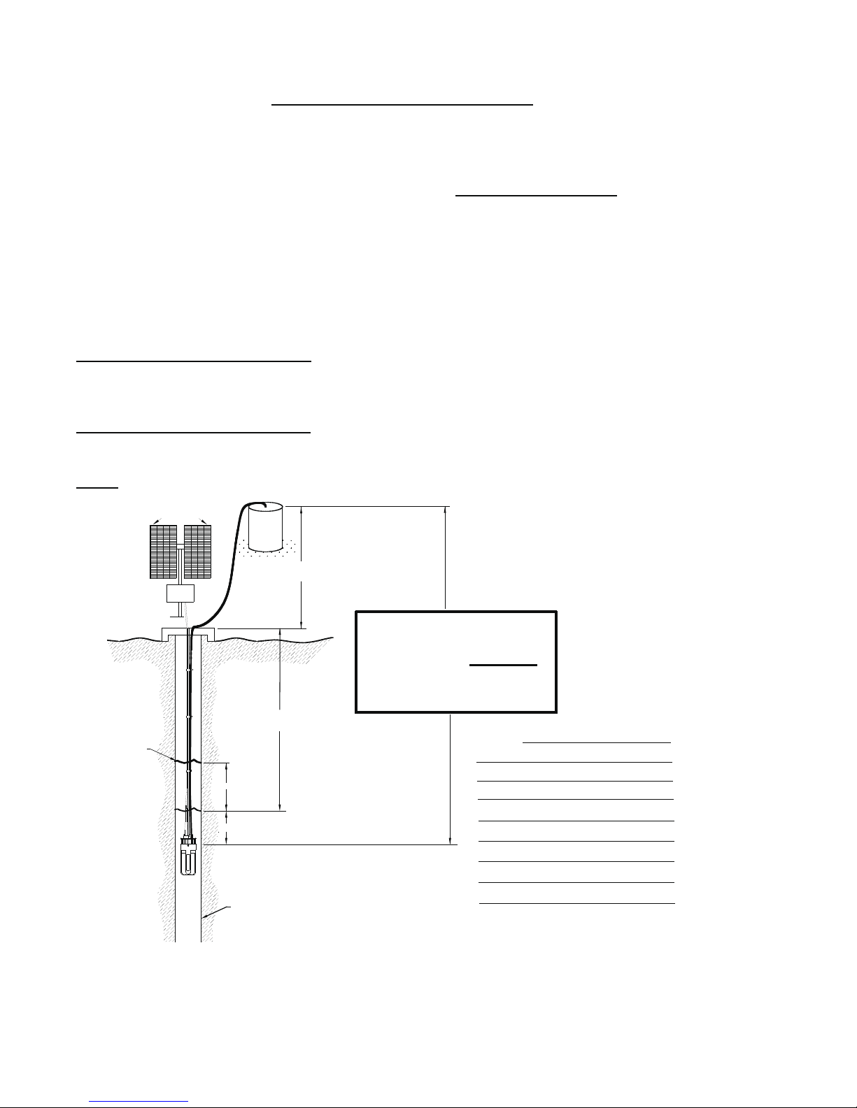
APPLICATION WORKSHEET
Please fill in for your records.
MODEL NUMBER_____________________________ PUMP DISTRIBUTOR:
SERIAL NUMBER_____________________________ Name_______________________________________________
MFG. DATE__________________________________ Address_____________________________________________
PURCHASE DATE_____________________________ City________________________________________________
TOTAL WELL DEPTH_________________FT(M) Phone( )__________________________________________
WELL RECOVERY
RATE________________________________________________________________________________________________________
SOLAR ARRAYINFORMATION:
MAKE/MODEL_______________________________________________________________________________________________
WATTS AVAILABLE (NO. OF PANELS X WATTS PER PANEL= )______________________________________________________
CONTROLLERINFORMATION:
MAKE/MODEL_______________________________________________________________________________________________
NOTE: Use of an LCB (Linear Current Booster) Unit is required for optimum performance.
SOLAR PANELS
CONTROLLER
DISCHARGE HEAD = H1
STORAGE
TANK
WATER LEVEL = H2
DRAW DOWN
SUBMERGENCE = H3
WELL CASING DIAMETER=_________IN(cm)
LEVEL
STATIC WATER
H1= DISCHARGE HEAD =_________FT(M)
+ H2=WATER LEVEL=_________FT(M)
+ *H3=SUBMERGENCE= FT(M)
**TOTAL VERTICAL LIFT=__________FT(M)
**NOT TO EXCEED 230 FT(70m)
(WHEN PUMPING)
(ABOVE GROUND)
*NOT TO EXCEED 100 FT(30m)
Comments:
(H1 + H2 + H3)

15
TERMS:
H1=DISCHARGE HEAD = Vertical distance in feet from ground level to level of water in elevated storage tank.
H2=WATER LEVEL = Vertical distance in feet from level of water in well when pumping up to ground level.
H3=SUBMERGENCE = Vertical distance in feet from level of water in well when pumping, to pump position in well.
Note: DO NOT submerse the pump deeper than necessary unless the water level is known to
be highly variable (Pump may operate dry for short periods of time.).
Draw down =Vertical distance in feet from static water level to water level when pumping.
Note: Make sure the pump is installed below the lowest anticipated water level.
Consider the seasonal changes in the region.
TOTAL VERTICAL LIFT= H1+H2+H3
12 VDC FLOW CHART
TOTAL FLOWRATE SOLARARRAYSIZE CURRENT
VERTICALLIFT PERHOUR MINIMUMTOTALPOWERRATING AMPS
STTAWRTLLAGSRETEMTEEF
20 6.1 56 212 22 1.2
40 12.2 54 204 28 1.5
60 18.3 52 197 33 1.8
80 24.4 50 189 37 2.0
100 30.5 49 186 40 2.1
120 36.6 47 178 45 2.4
140 42.7 46 174 51 2.7
160 48.8 44 166 56 3.0
180 54.9 43 163 61 3.3
200 61.0 41 155 64 3.4
230 70.1 36 136 72 3.9
24 VDC FLOW CHART
TOTAL FLOWRATE SOLARARRAYSIZE CURRENT
VERTICALLIFT PERHOUR MINIMUMTOTALPOWERRATING AMPS
STTAWRTLLAGSRETEMTEEF
20 6.1 117 443 58 1.5
40 12.2 114 432 65 1.7
60 18.3 109 413 78 2.1
80 24.4 106 401 89 2.4
100 30.5 103 390 99 2.6
120 36.6 101 382 104 2.8
140 42.7 99 375 115 3.1
160 48.8 98 371 123 3.3
180 54.9 93 352 135 3.6
200 61.0 91 345 141 3.8
230 70.1 82 310 155 4.1
16
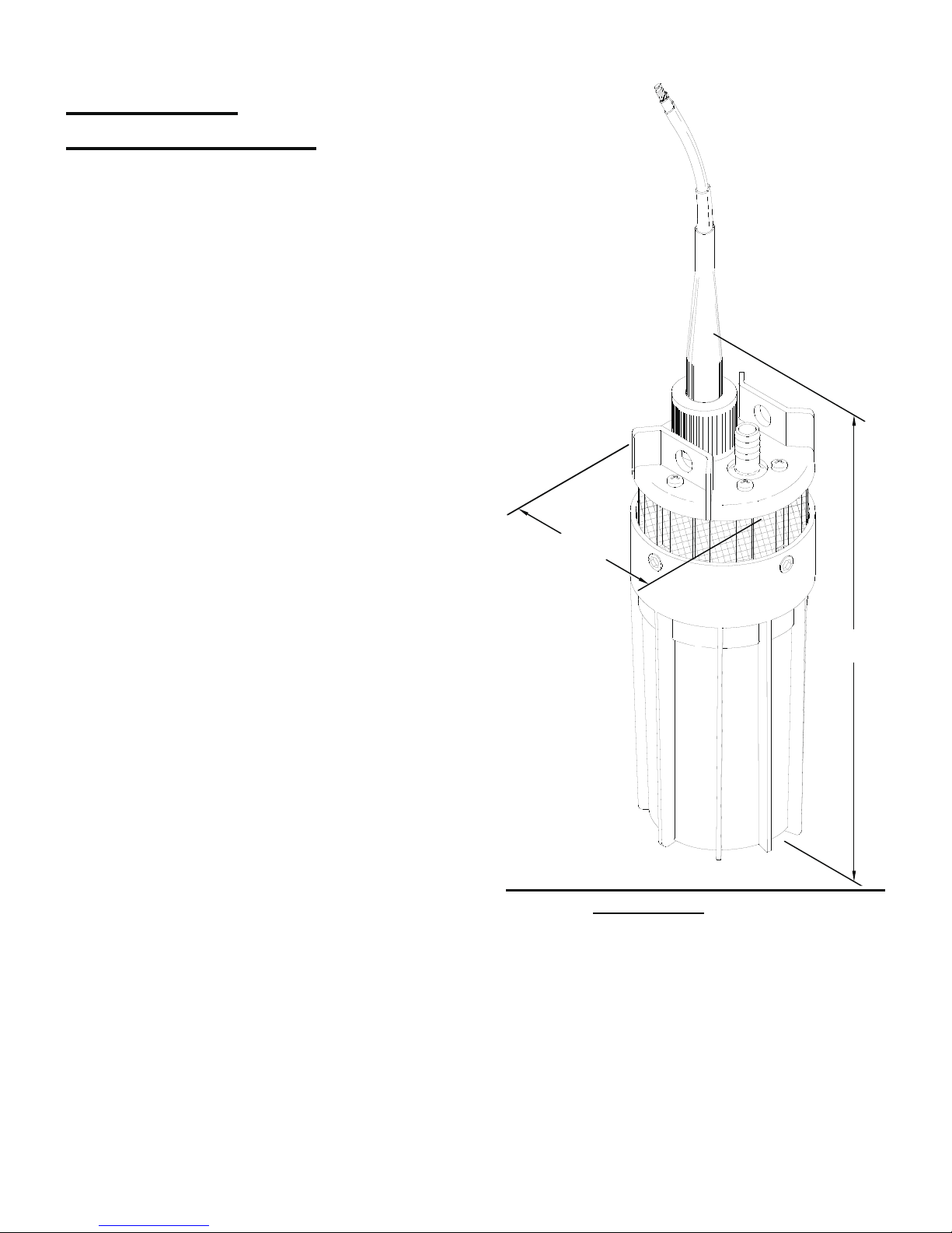
TECHNICAL
SPECIFICATIONS:
MODEL NUMBER: YM 2440-30
PUMP DESIGN: Positive Displacement
3 Chamber Diaphragm Pump
CAM: 3.0 Degree
MOTOR: Permanent Magnet, P/N 11-175-00
Thermally protected
VOLTAGE: 24 VDC Nominal
WATTS: 120W
AMPS: 4.0 MAX
FUSE: 7.5 AMP (Automotive)
INTERNAL BYPASS: 105-110 P.S.I. MAX (7.2-7.5 bars)
MAXIMUM LIFT: 230 ft (70 M)
MAXIMUM SUBMERSION: 100ft (30 M)
OUTLET PORT: 1/2" (12.7 mm I.D.) Barbed Fitting
for 1/2" I.D. (12.7 mm I.D.)Tubing.
INLET: 50 MESH STAINLESS STEEL SCREEN
MATERIALS: HIGH STRENGTH ENGINEERED PLASTICS
and STAINLESS STEEL FASTENERS
TYPICAL APPLICATIONS: Potable water well pump. DIMENSIONS: Inches(Millimeters)
Design and specifications are subject to
change W/Onotice.
NET WEIGHT: 6 lbs (2.72 kg)
(95 mm)
3.75 in.
(305 mm
)
12 in.

17
TOOLS REQUIRED FOR INSTALLATION & MAINTENANCE
*#1 and #2 Phillips Screwdriver Wire Cutters
*5/64" Allen Wrench Wire Strippers
*5/32" Allen Wrench Pliers
*3/16" Allen Wrench Dry Cloth or Cotton Tipped Applicator for cleaning O-Ring grooves
Electrical Tape
Tie wraps
*Note: A tool kit is available, components included are listed above.
NOTES:____________________________________________________________________________________
____________________________________________________________________________________________
____________________________________________________________________________________________
____________________________________________________________________________________________
____________________________________________________________________________________________
____________________________________________________________________________________________
____________________________________________________________________________________________
____________________________________________________________________________________________
____________________________________________________________________________________________
____________________________________________________________________________________________
____________________________________________________________________________________________
____________________________________________________________________________________________
____________________________________________________________________________________________
____________________________________________________________________________________________
____________________________________________________________________________________________
____________________________________________________________________________________________
____________________________________________________________________________________________
____________________________________________________________________________________________
____________________________________________________________________________________________
____________________________________________________________________________________________
____________________________________________________________________________________________

WARRANTY
LIMITED WARRANTY PROCEDURE
SINGFLO warrants its pump to be free of defects in material and workmanship to the original retail
purchaser for the period of one year beginning with the purchase date of the unit or, in the absence of
proof of purchase date, one year from the date of manufacture as shown on the pump, not to exceed
two (2) years in any event. Each pump has been operated and tested before being shipped from
SINGFLO's factory. During the warranty period if the pump is not operating correctly, you may return it
freight pre-paid to your local distributor, dealer or directly to SINGFLO.
Upon SINGFLO's inspection, any unit found faulty due to manufacturing defects will be repaired or
replaced at no charge. This warranty does not apply to any damage resulting from misuse, negligence,
accidents, improper installation or wiring. Abuses such as removal of the SINGFLO label, improper
repair, installation, application, or damaged lower housing assembly due to running dry, are also not
considered warrant able. There will be charges applied for any of the above mentioned non-warrantable
items.
If you send the pump to us for prompt repair, please package it carefully to avoid shipping damage.
Enclose your name, address, a phone number where you may be reached and your proof of purchase
date.
The above represents our warranty policy. Under no circumstances will we assume or accept
responsibility for unauthorized expenditures, losses, or any costs greater than the basic pump value.
Table of contents
Popular Water Pump manuals by other brands

Zoeller
Zoeller ProPak 507 installation instructions

Summit
Summit SP Installation, operation and maintenance manual

Wacker Neuson
Wacker Neuson PDT 2A Operator's manual

GEL
GEL DOSAMATIC PP Installation, use and maintenance manual

Atlas Copco
Atlas Copco WEDA L110 Instruction handbook

CET
CET PFP-18HPVGD-2D Instruction handbook

CET
CET PFP-11hpHND-EM Instruction handbook

Speck pumpen
Speck pumpen BADU Spyder I operating instructions

Stenner Pumps
Stenner Pumps SVP4L1 Installation and maintenance manual

Knauer
Knauer Azura V6840 user manual

EINHELL
EINHELL ROYAL HW 1300 Niro/Niro operating instructions

Parker
Parker DCP3 installation manual


