Affetti Pumps MSP-E User manual


2
INDEX
GENERAL INFORMATION pag. 2
EXECUTION
PUMP BODY
IMPELLER AND ROTOR
CONTAINMENT SHELL
INTERMEDIATE ADAPTOR
INTERNAL MAGNETIC CORE ……………………………………………………………………………………………………………
EXTERNAL MAGNETIC CORE
BUSHINGS
BASE
MARKING
GUARANTEE AND CERTIFICATION
” “
” “
” “
” “
” “
pag. 3
” “
” “
” “
” “
PRE - INSTALLATION pag. 4
PACKING
TRANSPORT
INSPECTION
STORING
” “
” “
” “
” “
INSTALLATION pag. 5
POSITIONING OF THE MACHINE
SUPPORT BASE AND FOUNDATIONS
CONNECTION WITH THE TUBES
CONNECTION OVER HEAD………………………………………………………………………………………………………………
MOVABLE CONNECTION CARRIAGE…………………………………………………………………………………………………...
CONNECTION OF THE ELECTRIC MOTOR
CONTROL INSTRUMENTS ………………………………………………………………………………………………………………..
” “
” “
” “
pag. 6
pag. 7
“ “
pa
g
. 8
OPERATION pag. 9
START OF THE PUMP
STOP OF THE PUMP
TEMPERATURES……………………………………………………………………………………………………………………………..
CAPACITY RANGE
ACUSTIC PRESSURE
” “
” “
pag. 10
” “
” “
HINTS ON CORRECT OPERATION pag. 11
PREVENTIVE MAINTENANCE
CRYSTALLIZATION OF THE PUMPED LIQUID
CHANGE OF THE PUMPED LIQUID
EVENTUAL DRY FUNCTIONING OF THE PUMP………………………………………………………………………………………...
IMPURITIES CONTAINED IN THE PUMPED LIQUID
” “
” “
” “
pag. 12
” “
TROUBLES AND EVENTUAL CAUSES pag. 13
THE PUMP DOES NOT EROGATE ANY LIQUID
THE PUMP DOES NOT GIVE SUFFICIENT CAPACITY
THE PUMP WORKS UNDER AN INSUFFICIENT PRESSURE
THE PUMP IS DISCONNECTED OR OR DOES NOT PRIME AND STOPS EROGATION
THE PUMP ABSORBS AN EXECESSIVE POWER
THE PUMP CAUSE VIBRATION AND NOISE…………………………………………………………………………………………….
THE SEALING DEVICE IS SUBJET TO RAPID WEAR
” “
” “
” “
” “
” “
pag. 14
” “
CROSS SECTION OF THE PUMP pag. 15
MAINTENANCE AND REPAIR OPERATIONS pag. 17
REMOVAL FROM THE PLANT
DISASSEMBLY OPERATION
ASSEMBLY PROCEDURE OF THE PUMP………………………………………………………………………………………………..
RECOMMENDED SPARE PARTS …………………………………………………………………………………………………………
DISPOSAL
” “
” “
pag. 18
pag. 19
“ “

3
GENERAL INFORMATION
EXECUTION
The pumps of this series have been developed by applying the properties of magnetic fields for the pumping
of corrosive liquids, with particular attention to a rugged construction, an easy access for maintenance and
hydraulical efficiency. They do not mount any kind of seal-system: that is why the pumped liquids cannot
draw outside the pump body, avoiding this way any possible pollution of the surrounding environment. On
the contrary, this could be possible if the most sophisticated mechanical seals are applied. The design of the
volute and at the same time of a bladed channel guarantees a high output with minimum overall dimensions
and excellent performances. Each machine is combined with a series of motors of different power and
satisfies the most diversified needs by means of an optimum ratio between capacity and head in function of
the specific weight of the pumped liquid assuring a low energy consumption. The installed motors are in
compliance with the IEC or NEMA standards, mount a protection according to IP55, are built in insulation
class F and are connected with the pump body through an adaptor of technopolymeric material (MSP-E) or
in cast iron (MSP-N) maintaining a sufficient distance to protect the motor against eventual leakages of the
pumped liquid.
PUMP BODY
The pump body is of the volute casing type with the delivery port located in central position. The
filling chamber, provided with oil fill and drain plug is mounted and connected to the pump body at
the front.
The connections are with free flanges (ISO ANSI JIS).
IMPELLER AND ROTOR
The impeller is of the half-open or closed type and is independent from the rotor with which it
rotates integrally.
The latter serves for connecting the internal magnetic coupling to the impeller ad it also supports
the rear rotating bushing.
CONTAIMENT SHELL
It is entirely composed of plastic material of just one single piece. lt has got thicknesses and materials fit for
the pump liquid.
INTERMEDIATE ADAPTOR
The intermediate adaptor has got a very sturdy construction and is entirely composed of a technopolymer
(MSP-E) or cast iron (MSP-N). lt has been specially designed to keep the electric motor in a distance from
the rest of the pump and to contain the containment shell and the external magnetic coupling.

4
INTERNAL MAGNETIC CORE
The internal magnetic core is entirely protected by a coating in plastic material, resistant to all the different
pumped liquids. lt is composed of permanents magnets which are fixed on a metal support. The
characteristic of this part of part of the pump is to be indipendent of the rest of the rotor, so it can be easily
replaced in case of break without changing the whole rotating unit.
EXTERNAL MAGNETIC CORE
The external magnetic core is rigidly fixed on the motor shaft, with which rotates as an integral part. Its
component parts are the following:
the permanent magnets.
the support on which the metal bars are fixed.
the coupling which connects the core to the motor shaft.
BUSHINGS
The rotor, the impeller and the Internal magnetic core are driven by rotating bushings in loaded PTFE or in
silicium carbide SiC and have got as fixed corresponding parts some rings of pure alumina AI203or silicium
carbide SiC.
BASE
The base which supports the motor is of bent lamination of stainless steel according to AISI 304 (MSP-E).
The MSP-N pumps mount intermediate adaptors of cast iron, equipped with feet, which support both the
pumping unit and the motor by lifting them from the control base.
MARKING
Each machine is equipped with a label on which you find all the data prescribed by the Machine Decree
2006/42/EC
For an eventual spare part request please cite the machine number of the pump.
GUARANTEE AND CERTIFICATION
Automatically and without a special request of the customer our company emits a guarantee and test
certificate. Moreover we are ready to supply all possible types of certificates according to the requirements of
our customers.

5
PRE - INSTALLATION
PACKING
The structure of the packing and the employed materials are chosen according to shape, dimensions and
weight of the machine, which has to be shipped.
We may adopt solutions of the following type:
Cardboard box with filling material for machines of small dimensions;
Cardboard box and wooden pallet with filling material for bigger pumps;
Wooden pallets exclusively for machines, which due to their structure need an external covering;
Wooden box for long and very heavy pumps.
TRANSPORT
A good transport is very important for the fine functioning of a machine and for this reason this operation
merits our full attention.
The charge and the discharge of the delivered items have to be performed in dependence on the shape, the
weight and the type of packing.
The lifting should be done without soliciting the fragile parts (body and connections) of the pump. The
packed machine should be set down gently and without a blow and has to be fixed and supported so that
during transport it does not leave its original position and is not exposed to strong vibrations.
The discharge in the customer's store has to be performed with the same precautions as the charge.
INSPECTION
At the arrival of the machine has to be carried out an accurate inspection to make sure that during transport
did not occur any damage. If this should be the case, please contact the responsible agent.
Sometimes for safety reasons components and accessories are separately packed inside the main packing.
After the removal of the pump please accurately check the contents of the packing.
Our company is free from any obligation to reply on every request of compensation for damages advanced
by the customer or third persons.
STORING
Normally the pump is delivered with the objective of a short-term installation.
If a long storing period is foreseen, please make sure that the storing site is dry and clean in order to avoid
damages before installation.
In the cited case we advise that before installation on the plant the pump should be carefully cleaned by
eliminating eventual foreign bodies, which could compromise the correct functioning. At last have to be
removed the protection taps from the delivery and suction orifices.

6
INSTALLATION
POSITIONING OF THE MACHINE
The pump has to be mounted in the best possible position to assure
An easy installation of the suction and delivery tubes. The machine should be positioned in immediate
neighbourhood of the suction column or tank. Elbows and contractions should be excluded as far as
possible.
An easy access for inspection during normal duty or for maintenance operations.
Recommended Safety Measures
Above all you have to keep a sufficient safety distance between the machine and an eventual
passage for persons. Do not store in spaces together with inflammable or explosive materials.
To assure the safety of the operator or any other interested person the positioning of the pump
should be performed by taking into consideration eventual ruptures of the body or overflows of
highly corrosive liquid during operation under pressure.
Before the installation of the machine you should make sure that the interruptor is in the "zero"
position (OFF) and disconnect the appliance from the supply to avoid the accidental actuation of the
moving parts.
These operations should be performed only by specialized and trained staff.
Caution! This machines generates magnetic fields!
SUPPORT BASE AND FOUNDATIONS
These parts have to be realized with suitable materials and guarantee the stability of the support and its
surrounding area.
Foundations in reinforced concrete layed on solid ground are highly recommendable. The base has to be
placed in a horizontal position. It should be checked by a water level and is fixed by anchoring holes applied
on the base itself or on the feet of the motor with screws of stainless steel according to AISI 316.
In case of misalignment between the pump and the tubes we recommend the use of metal shims (AISI 316)
to equal the differences, which occurred during the connection.
CONNECTION WITH THE TUBES
The suction and the delivery tubes, which are connected with the mouthpieces of the machine, should not
produce any excessive charges or disproportions.
Elevated forces and excessive movements transmitted to the tubes may cause damages on the pump. For
this reason we recommend to use brackets and rigid fixations for the delivery and suction collectors. This
operation is essential and indispensable, if you want to obtain a correct operation of the machine.
Another special requirement, which should be strictly observed, is the parallelism between the flanges of the
tubes and of the electric pump: a faulty positioning of these tubes could cause forced unnatural alignments
of the various connected collectors and subsequently this could cause leaks on the gaskets or even cracks
on some tracts of the tube.
The suction tube has to controlled and flushed before the connection to guarantee that there are no solid or
foreign bodies inside, which could damage the delicate parts of the machine.
Keep at an appropriate distance from electronic instruments; there is risk of generating nexpected
phenomena.
It is not advisable for persons with pace maker to approach the pump.

7
CONNECTION OVER HEAD (Fig. 1 )
The pumps of this series have been designed above all for installation as shown in figure 1.
Connection of the suction piping always requires a horizontal section as short as possible and a
maximum distance of 4 metres between the delivery port and free liquid surface.
It is advisable to install a filter (do not mount the foot valve) at the end of the suction manifold if
the liquid contains impurities. A large radius bend brings the piping from a vertical position to a
horizontal position until reaching the suction port of the pump.
It is not recommended to fit elbows or fittings which could either delay or even inhibit the
priming phase.
To drain the suction manifold, it is advisable to mount of valve (3/8").
The delivery manifold should be provided with:
Regulating valve
Check valve
I
D
A
L
S1
D
H
C
R
Q
O
MT
B
U
J
Z
V
P
(A) Suction pipe (O) Delivery valve
(B) Manometer (P) Pressure switch
(C) Filter (Q) Cotnrol panel
(D) Bracket (R) Chek valve
(H) Charge tube (S1) Level
(I) Discharge valve (T) Termometer
(J) Suction valve (U) Pump
(L) Supply vat (V) Air vent valve
(M) Delivery pipe (Z) Pressure-vacuum gauge
FIG.1

8
MOVABLE CONNECTION ON CARRIAGE
As far as the safety of the operator reliability, performances and life are concerned the use of the self-
priming centrifugal pump with magnetic drive mounted on a carriage certainly is the less suitable operating
solution. The customer should be familiar with the limits of operation, which should be carefully observed
during this kind of use.
Please use machines, which do not exceed the following operational values:
maximum capacity 35 mc/h
maximum head 2.5 Bar.
The tract of the suction tube has to be adequately designed so that a tortuous course, constrictions and
various obstacles, which may cause difficulties in the free flow of the liquid through the passage of the tube,
are avoided.
Please use a tube of anti-acid material, if possible a reinforced type, and metal clamps to fix this tube firmly
to the hose adaptors of the suction and delivery orifices.
On the rear side of the pressing pipe should be mounted an exclusion valve.
If in the pumped liquid might be contained crystals or foreign bodies, you should install a filter (with 3 to 5
times the diameter of the tube) on the supply vat or tank.
If there are different pumped products, check that the materials of the pump are compatible and apply a
draining valve (to be requested in the order), which allows the emptying of the suction tube and the
successive cleaning with clear water.
CONNECTION OF THE MOTOR
We advise to follow with care the schemes, which the producer of the motor illustrates in the terminal box or
in the instruction manual or else follow the wiring diagrams given below..
Recommended Safety Measures
It is highly dangerous to start the pump before having completed the installation. The assembly
operations have to be performed by specialized workers.
U1 V1 W1 U1 W1 V1

9
CONTROL INSTRUMENTS
To guarantee a correct functioning the machine should be equipped with instruments, which control every
instant of its operation, for example.:
A manual vacuum gauge installed on the rectilinear tract of the suction tube in the immediate
neighbourhood of the pump allows to check and to calculate the N.P.S.H. value.
A manometer installed near the exit orifice for the measurement of the operating pressure.
A wattmeter or an ammeter for the examination of the input power and the comparison of the values
indicated on the motor label with the effectively absorbed energy.
A thermometer for measuring the temperature of the liquid. This parameter is very important and has to
be kept under control to avoid the exposure of the machine to excessive temperatures, which could
damage the materials of the pump (see paragraph "TEMPERATURES", page 10).
A pressure gauge or an automatic safety device, which blocks the pump in case of functioning without
liquid or a minimum level probe, which is applied to the supply vat or tank.
In any case you should carefully follow the instructions for installation put at your disposal by the
producer of the appliance.

10
OPERATION
START OF THE PUMP
Before starting the pump you should take the following steps:
a) please make sure that the delivery and the suction tubes are correctly connected and that all the bolts are
well tightened.
b) Full open the gate valve on the suction line and the one of the air vent line, but not before
having fully closed the delivery valve and the vent valve located on the suction manifold.
c) The pump must be fully flooded. Each time it is started, fill, by unscrewing the plug at
the top of the pump body (item 38, see page 16), the priming chamber, so that the liquid
level reaches the suction port. If the conditions do not correspond to the ones just
described above, proceed to pour, into the pump body and up to the level of the suction
port, liquid compatible with the liquid to be pumped and POSSIBLY NOT HOT.
d) After having completed the phases (a), (b) and (c) please make sure that the sense of rotation of the
motor is correct (see arrow on the cap) by actuating the switch with a rapid sequence of start and stop.
Please do not insist on making the pump turn in the inverse sense, since this operation could cause serious
damages on the machine.
To change the sense of rotation you only have to invert two of the three terminal wires of the motor.
e) Start the motor and slowly open the exclusion valve on the delivery until you reach the required capacity
for operating the pump (Please do not leave the sluice valve of the pressure tube closed for a long time).
f) Check the input values of the pump by taking into consideration the values marked on the motor label and
make sure that these values (input power in kw or intensity in ampere) are not exceeded.
It is a requirement to apply a soft-start or an inverter for motor size equal to or greater than 11Kw.
STOP OF THE PUMP
If the delivery tube is equipped with a check valve, the stop of the machine may take place without any
particular precaution.
In the negative case the check valve has to be slowly closed before stopping the motor so that water
hammers in the pressure system are avoided and the liquid can flow out through the pump. Only at this point
you may close the eventual auxiliary flowing from an external source, provided that the machine is equipped
with such a device.
We recommend short periodical operating controls of the pump.
Recommended Safety Measures
In the start as well as in the stop phase of the pump the operator should be adequately equipped for
reasons of health preservation.
This means rubber boots, anti-acid overalls, helmet with protective visor for the face and the
indispensable equipment for each operator, which excludes the risk of physical damages.
It is absolutely forbidden to introduce the fingers or other parts of the body into the orifices and the
various openings. The pump is equipped with movable parts.
The mentioned operations have to be performed by skilled staff.
Caution! This machine generates magnetic fields!
Keep at an appropriate distance from electronic instruments; there is risk of generatine unexpected
phenomena.
It is not advisable for persons with pace maker to approach the pump.

11
TEMPERATURES
For the correct operation of the machine should be observed the following temperature values, which are
listed on the data sheet.
Moreover we indicate the maximum and minimum operating temperatures, which have to be strictly
observed for a continuous working cycle of eight hours.
PP = 0° C +75° C
PVDF = -10° C +90° C
The relative material is specified on the data sheet, on the delivery bill and on the invoice.
For quick efficient primping, it is advisable to pump liquids not exceeding +30°C
CAPACITY RANGE
The choice of the type of pump, impeller and motor takes place at the moment of ordering by taking into
consideration the capacity and head data requested by the customer.
The user should carefully observe the operating conditions mentioned on the data sheet and especially the
data regarding capacity and head at the installation site to which the machine is destined.
Please do not force the pump to work in the two extreme positions, i. e. too far on the right hand or too far on
the left hand of the characteristic line, since serious problems might arise. For this reason we recommend to
work with the intermediate point of the curve.
ACOUSTIC PRESSURE
If the present product is used in an appropriate and a permanent way, the noise exposure, which depends
on the relative environment, may reach maximum values of no more than 80 dB (A).

12
HINTS ON CORRECT OPERATION
PREVENTIVE MAINTENANCE
The functionality of the pump depends on the number of working hours, the service conditions, the used
construction materials and on the care with which the pump is treated during its operative life. A daily check
during operation helps to avoid complications and assures an immediate intervention in case of damages.
The pump has to function without vibration or abnormal noise. If similar events should occur, please
intervene and check the status of the rotating organs like bushings, and the motor bearings and if
necessary replace them.
Please control the characteristics of the pumped liquid (temperature, specific weight and chemical
composition).
If these characteristics change, the operating conditions and the performances of the machine may
change too.
Please accurately check that changes in the pumped solution are compatible with the characteristics of
the machine by taking into account the indications on temperature given in the present manual in the
paragraph on "TEMPERATURES", page 10, while for the other parameters we advise to contact your
local reseller or our company.
Please make sure that capacity and pressure are according to the projected values and that they have
not been subject to changes, which may negatively influence the internal parts of the pump.
The partial rupture of the impeller blades may be caused by a reduction of the hydraulic performances. In
this case you have to replace the faulty part.
The filter housing has to be checked in periodical intervals and cleaned, if necessary.
Please make sure that the control instruments are completely efficient and that the machine always gets
the right signals.
Please check the control base and make sure that there are no losses of liquid. ln this case we
recommend a complete check of the pump body and of the containment shell just to make sure that they
have not any breakings.
The replacement of the damaged parts has to take place in a dry and clean environment.
CRYSTALLIZATION OF THE PUMPED LIQUID
The crystallization of liquids is a problem, which should not be underestimated. For this reason we invite the
user to ask the producer for information on the pumped product and for information on the minimum value at
which the liquid starts the crystallization process.
CHANGE OF THE PUMPED LIQUID
For the replacement of the pumped liquid you have to take the following measures:
Close the delivery valve.
Fully empty the piping and pump by opening the drain gate valve located on the suction line
and the drain plug (item 42 see page 16) .
Clean internally the pump and the containment shell with water or a suitable liquid by avoiding eventual
chemical reactions, which might cause irreparable damages to the machine and the operator.
Do not discharge the solution obtained from the cleaning of the internal parts of the pump into the
environment.

13
Recommended Safety Measures
To operate in conditions of extreme safety during the control of the running machine the operator
should be adequately equipped.
Rubber boots, anti-acid overalls and helmet with protective visor for the face are the indispensable
equipment for the persons who have to operate without running the risk of physical damages.
The described operations have to be carried out by skilled staff.
EVENTUAL DRY FUNCTIONING OF THE PUMP
The pump should be always flooded each time the pump body is empty and does not
contain a sufficient quantity of liquid to reach the suction port.
The principal rule, which you should observe at any instant, says that for a machine of this type you must
avoid in every possible way that it functions without liquid in order to exclude damages in the internal
parts.
There are many situations, in which this drawback might occur and some of them are listed below. Very
frequently this occurs during the charge and discharge operations of the tank trucks. In this case you should
equip the machine with suitable instruments, which block operation in case of a lacking flow of pumped
liquid (see paragraph entitled "CONTROL INSTRUMENTS" on page 8).
Other causes are:
The malfunction of the control instruments due to the encrusting and corrosive action of the pumped
liquids, which attacks the most exposed organs;
A poor or inefficient maintenance of the filter.
The total or partial absence of liquid in the vat or the tank.
The formation of air pockets and cavitation due to a wrong dimensioning and an inadequate structure of
the suction collector.
IMPURITIES CONTAINED IN THE PUMPED LIQUID
Due to their nature and design the pumps of this series have got low endurance levels in case of liquids,
which contain solid, abrasive or filamentary particles.
We recommend to avoid, if possible, the pumping of such fluids or to install a filter on the suction tube. In
any case you should take into consideration that the maximum allowable concentration of impurities is 3 %.
With higher values could be caused serious problems on the bushings, the impeller, the body, the
containment shell and the internal parts of the machine.

14
TROUBLES AND EVENTUAL CAUSES
THE PUMP DOES NOT EROGATE ANY LIQUID
1) The pump and the suction tube are not completely filled with liquid. There are air pockets, which have to
be purged.
2) The non-return valve on the suction tube is blocked and totally closed.
3) The impeller is blocked by rubbish or incrostations present in the liquid.
4) The total head required by the plant is superior to the projected head of the pump.
THE PUMP DOES NOT GIVE SUFFICIENT CAPACITY
5) Air is penetrating into the suction tube through the flange gaskets.
6) The passages of the impeller are partially or totally obstructed by foreign bodies.
7) The rotation speed of the motor is too low.
8) The impeller is worn out or damaged and the distance to the pump body is too big.
9) The sense of rotation is wrong.
10) The course of the suction duct is not exact.
11) The filter on the suction portion is obstructed.
12) The suction tube has got an underdimensioned passage section or an excessively tortuous course.
13) The liquid level is too low.
14) The magnetic coupling does not transmit the rotatory movement. Please, check that the bushings or the
impeller are not blocked.
THE PUMP WORKS UNDER AN UNSUFFICIENT PRESSURE
15) The viscosity of the liquid is higher than foreseen. See also points 4-6-7-8-9.
THE PUMP IS DISCONNECTED DOES NOT PRIME AND STOPS EROGATION
16) The transported liquid contains an excessive quantity of air or gas. See also points 5-11-13.
17) Temperature of the liquid has risen with respect to the initial conditions, or else it is too high.
18) The specific gravity or viscosity of the pumped solution is higher than the design values.
19)The capacity increased by more than the fixed value.
THE PUMP ABSORBS AN EXCESSIVE POWER
20) The specific weight or the viscosity of the pumped solution is higher than the projected values.
21) The pump performances are higher than foreseen.
22) The rotation speed is too high.
23) Defects or mechanical damages on the machine: unbalanced rotor, excessive friction of the bushings or
of the impeller, blocked motor bearings, etc.

15
THE PUMP CAUSES VIBRATION AND NOISE
24) Operation at a capacity, which is too low for the application.
25) The tubes or the foundations are not sufficiently rigid.
26) The motor bearings are worn out or damaged. See also points 6-22.
27) The pump is subject to cavitation. Please check the reasons for this abnormal functioning by taking into
consideration points 1-6-9-11-12-13.
THE BUSHINGS ARE SUBJECT TO RAPID WEAR
28)The pumped liquid contains foreign bodies or abrasive substances.
29)The gaskets or other employed materials are not suitable for the characteristics of the pumped liquid.
30)The pumped liquid causes the formation of air or gas.
31)At the machine arrives only a small quantity of liquid or no liquid at all.

16
CROSS SECTIONS

17
POS. DESCRIPTION MATERIAL POS. DESCRIPTION MATERIAL
1 Screw SS304 24 Cap EPDM-FPM-PTFE
2 Screw SS304 25 Static bushing Al2O3 - SiC
3 Cap EPDM-FPM-PTFE 26 Screw SS304
4 Intermediate adaptor PP - CAST IRON 27 Motor coupling ALUMINIUM
5 Containment sheel PP - PVDF 28 Motor -
6 Tirant SS304 29 Screw SS304
7 O-ring EPDM-FPM-FEP 30 Motor base SS304
8 Delivery flange CS + PP FG 31 Key CARBON STEEL
9 Covered nut PP - PVDF 32 Screw SS304
10 Suction flange CS + PP FG 33 Washer SS304
11 O-ring EPDM-FPM-FEP 34 Seeger PP - PVDF
12 Cap EPDM-FPM-PTFE 35 Pin PP - PVDF
13 Static bushing Al2O3 -SiC 36 Ring housing PP - PVDF
14 Cap EPDM-FPM-PTFE 37 Tirant SS304
15 Casing PP - PVDF 38 Stopper PP -PVDF
16 Rotary bushing PTFE CG - SiC 39 O-ring EPDM-FPM-FEP
17 Impeller PP - PVDF 40 Casing PP -PVDF
18 O-ring EPDM-FPM-PERF 41 O-ring EPDM-FPM-PERF
19 Rotor PP -PVDF 42 Stopper PP - PVDF
20 Washer CARBON STEEL 43 O-ring EPDM-FPM-PERF
21 Washer SS304 44 Diaphragm PP - PVDF
22 External magnetic coupling Nd-Fe-B 45 O-ring EPDM-FPM-PERF.
23 Rotary bushing PTFE CG - SiC

18
MAINTENANCE AND REPAIR OPERATIONS
REMOVAL FROM THE PLANT
Before disconnecting the pump from the plant please take the following steps.
a) Make sure that the pump is not under power.
b) Detach the plug from the electric switchboard.
c) Detach the electric cables from the terminal board and carefully isolate the ends.
d) Shut the suction and delivery valves, then open the emptying gate valve on the suction line and the air
vent valve on the delivery line, fully empty the liquid present in the piping and pump.
e) Loosen the drain plug on the pump body (item 42 page 16) and drain the liquid remaining inside.
After these steps you may begin with the removal of the machine from the plant.
Before disassembly you have to clean the entire body with water or an appropriate liquid. Please try to avoid
chemical reactions, which might cause irreparable damages to the machine and the operator.
Please do not discharge the solution obtained from the cleaning of the pump into the environment.
Recommended Safety Measures
To operate in conditions of extreme safety during the removal of the pump from the plant the
operator should be adequately equipped.
Rubber boots, anti-acid overalls and helmet with protective visor for the face are the indispensable
requisites for the persons who have to operate without running the risk of physical damages.
The described operations have to be carried out by skilled staff.
DISSASSEMBLY OPERATION
The disassembly should be carried out with the utmost care to avoid eventual damages on the internal parts
of the machine caused by a wrong use of pincers and screw-drivers.
The various components should be kept on a bench in the order of disassembly and be protected against
crash and dust.
After having prepared the table on which the pump is assembled and disassembled please proceed as
follows:
1Unscrew the pump mounting nuts (item 9) (right-hand thread) with a pipe wrench, size 18 or 22 mm (do
not use other types of spanners) .
2 Remove the pump body (item 40) fig. 2-3.
3Unscrew the nuts fastening the pump body to the intermediate adapter using pipe wrenches, size 18 or 22
mm (do not use other types of spanners)
4 Remove the diaphragm {item 44) fig. 4
5 Lift out the circlip (item 34) securing the impeller fig. 5 using relative circlip tool fig. 9.
6 Lift the impeller out from the rotor (item 17) fig. 6.
7 Remove the cover from te shell (item 36).
8 Refit the impeller (item 17) on the rotor (item 19) securing it with the circlip (item 34)
9 Lift out the rotor from the shell by grasping it with the impeller fig. 7
10 Lift out the shell (item 5) from the intermediate adapter (item 4) fig. 8
11 Back-off the screws (item 1) fastening the intermediate adapter to the electric motor
12 Detach the intermediate adapter (item 4) from the motor (item 28)
13 Back-off the screw (item 2) fastening the magnetic coupling (item 22-27) to the motor shaft
14 Remove the magnetic coupling (item 22-27) fig. 10
15 Ser relative puller to remove the static bushings if required (item 13-25) fig. 11

19
ASSEMBLY PROCEDURE OF THE PUMP
After having disassembled the pump and found out the parts, which have to be replaced, all the properly
functioning parts have to be carefully cleaned with water or an appropriate solvent. If you have to replace
parts, you must use original spare parts.
As the phase of disassembly also the assembly phase demands that all the operations have to be carried
out with extreme care.
Before proceeding to assembly, it is recommended to check the state of preservation of all the
elastomeric parts (items 3-7-11-12-14-18-24-39-41-43-45), of the static guide bushings (items 13-
25) and the rotary bushings (items 16-23), making sure that the clearance between them does
not exceed 0.6 mm.
Carefully check that the surfaces of the static bushings do not show rough zones or even cracker
zones.
Of the above described conditions do not fall within the limits and values listed, proceed to
replace the parts. For seating of the static bushings, make use of a press or fixture capable
of pushing the bushing into relative seat (before carrying out this operation, wet with the
soap and water or else apply a film a talc on the rubber components. Never use grease or
oil lubricants
16 Rest the electric motor, on the fan cover side, on a work bench
17 Tighten the screw (item 2) fastening the magnetic coupling to the motor shaft
18 Fasten the intermediate adapter (item 4) to the motor (item 28)
19 Insert the shell (item 5) in the intermediate adapter (item 4) fig. 4
20 Position the shell cover (item 36) on the rotor (item 19), then fasten the impeller (item 17) to the rotor
21 Insert the rotor-cover-impeller group in the shell (item 5) seating it with force
22 Fit the O-ring of the shell (item 18) in relative space
23 Mount the pump body (item 15) fig. 2-3
24 Insert body O-ring (item 43) in the groove of the pump
25 Insert the diaphragm (item 44) fig. 4 in the pump body (item 15)
26 Seat the O-ring (item 45)
27 Fasten the other half of the pump body (item 40) by tightening the mounting nuts (item 9) using a pipe
wrench, size 18 or 22 mm
Fig. 2 Fig. 3Fig. 4 Fig. 5 Fig. 6
Fig. 7
Fig. 8Fig. 9
Fig. 10 Fig. 11 Tools

20
Useful indications
The assembly and disassembly operations of the pump can be performed exclusively by persons
who have got basic mechanical knowledge and skills.
For a better understanding of the characteristic features sufficient notions on the materials, which
are used for the construction of the machine, are indispensable.
RECOMMENDED SPARE PARTS
To determine the minimum quantity of spare parts, which should be available for eventual replacements, you
should take into consideration the operating conditions (more or less heavy) and the number of
interchangeable units installed on the plant.
For each pump we normally advise to keep the following pieces on store:
a) One impeller (pos. 17) with its rotor (pos. 19).
b) One series of rotating bushings (pos.16-23) and one of stationary bushings (pos.13-25).
c) A complete series of gaskets (pos. 3-5-7-11-12-14-24-39-41-43-45).
d) A rotor (pos. 19)
e)
In your spare part orders please always cite:
Machine number of the pump.
Series and type.
Number and position of the component on the sectional drawing attached to the present manual.
Quantity of requested pieces.
DISPOSAL
The replaced spare parts or the pumps, which reached the end of their operative life, have to be submitted to
a careful selection in order to separate the various parts according to the materials. They should be stored
and if possible recycled. If this is impossible, please charge specialized and authorized companies with the
disposal.
Table of contents
Other Affetti Pumps Water Pump manuals
Popular Water Pump manuals by other brands

JABSCO
JABSCO 52700 installation guide

ITT
ITT GOULDS PUMPS 3180 Installation, operation and maintenance manual
GORMAN-RUPP PUMPS
GORMAN-RUPP PUMPS 81 1/2E52-B Installation, operation, and maintenance manual with parts list

Draper
Draper SWP110ADW instructions
Grundfos
Grundfos Unilift AP12 Installation and operating instructions

VARISCO
VARISCO J2 180 manual

Renkforce
Renkforce 1034029 operating instructions
Grundfos
Grundfos CU 301 Installation and operating instructions
Honeywell
Honeywell PC3F4344IUF00 Specification data

Oase
Oase ProMax Rain 4000 operating instructions
Flint & Walling
Flint & Walling FJ05S quick start guide
UNIBLOC
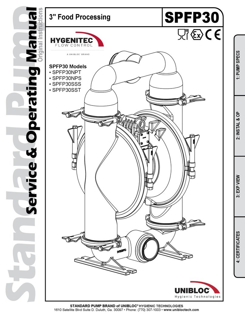
UNIBLOC Standard Pump SPFP30 Service & operating manual


