SingTel SingNet eVolve Business Fibre Broadband User manual

1
Troubleshooting
Guide for SingNet
eVolve Business
Fibre Broadband
Identify your issue and follow this step-by-step guide to troubleshoot
your SingNet eVolve Business Fibre Broadband.
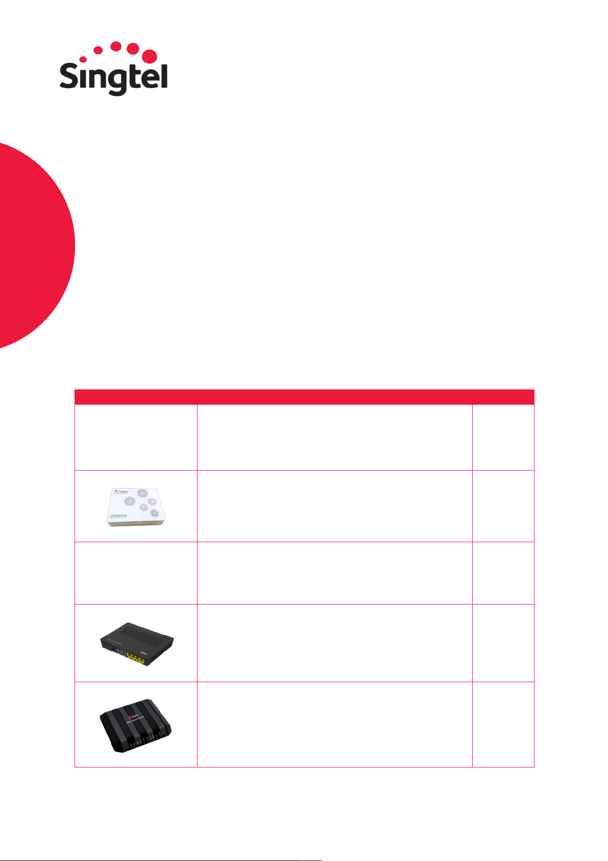
Your fibre broadband set up consists of:
Your Optical Network Terminal (ONT) and/or Wireless Router might differ from the images shown
due to the use of different models. Please refer to the guide from page 5 onwards for instructions on
how to troubleshoot the specific model of your hardware.
2
Please refer to the following set up guide to check if your ONT/ONR and wireless router are connected
correctly. You can refer to page 4 for a troubleshooting infographic to help you resolve set up issues.
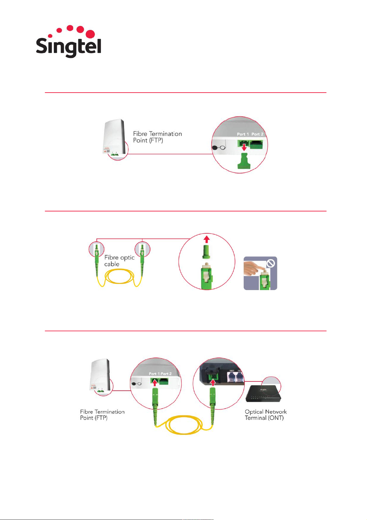
1
Unplug the green plastic cover from port 1 on the Fibre Termination Point (FTP).
Note: The FTP can be commonly found near your Optical Network Terminal (ONT) or Optical
Network Router (ONR).
2
Remove both green caps from the fibre optic cable. Do not touch the tip of the cable as dust and
fingerprints may cause interference with the connection and affect your internet speed.
Note: A fibre optic cable is made of glass – do not stretch, tie or bend sharply.
3
Connect the fibre optic cable from port 1 of the FTP to the Passive Optical Network (PON) port
located at the back of the ONT or ONR. Ensure that the cables are firmly plugged into the ports.
Depending on the model of your ONT/ONR,the port may be located on the back or under the
device.
3
4
Connect the ONT/ONR to a power source and switch it on. Wait for the Power and PON lights to
turn green. If your ONT Power and PON lights are blinking or red, please refer to page 7 for an
explanation of what the lights represent based on your specific device model.
Note: If the PON light continues to flicker/blink after 2 minutes, switch off the ONT and repeat steps
1 to 3. Ensure that the fibre cable is firmly plugged into the ports on the FTP and the ONT.
5
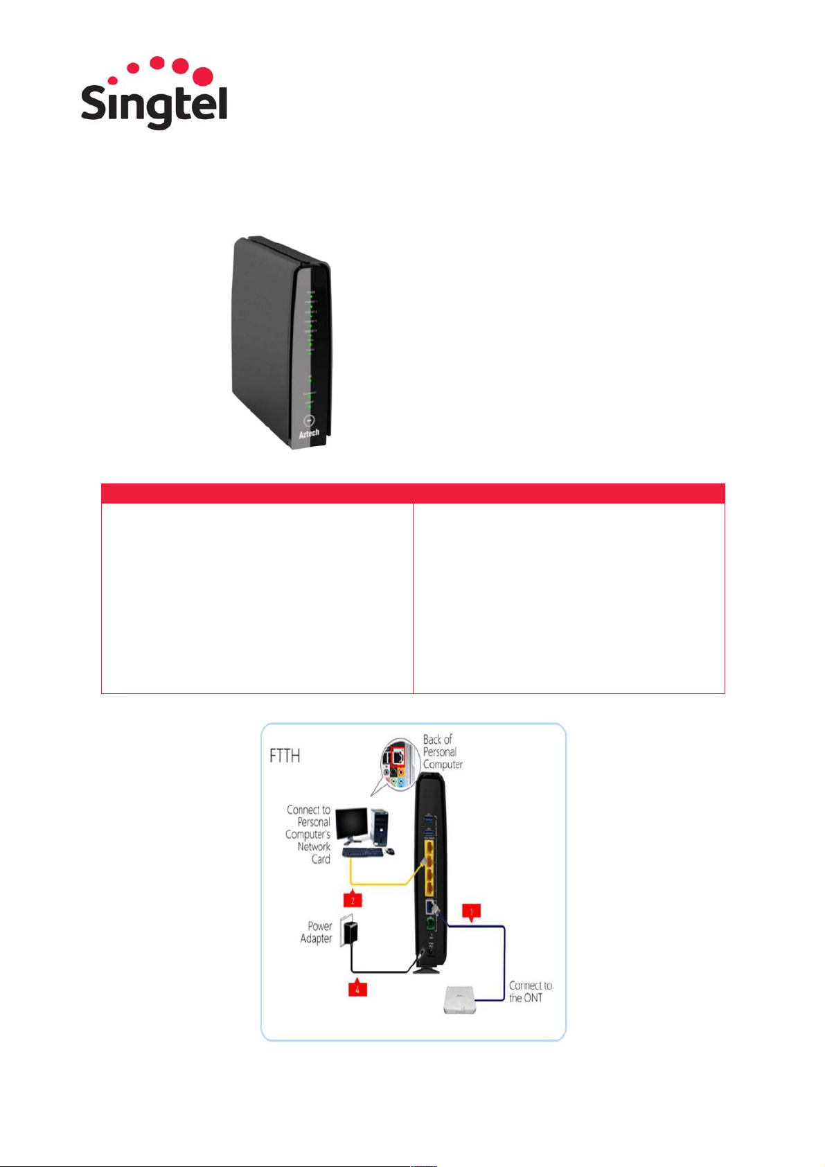
Use an RJ45 Ethernet cable to connect LAN 1 port on the ONT/ONR to the Internet / Ethernet /
WAN port of the Wireless Router.
6
Connect your Wireless Router to a power source and switch it on. Wait for Power and Internet lights
to turn green. Do refer to page 13 onwards for an explanation of what the status lights represent
based on your specific router model. If you need to reboot, please follow the instructions provided
for your router model.
4
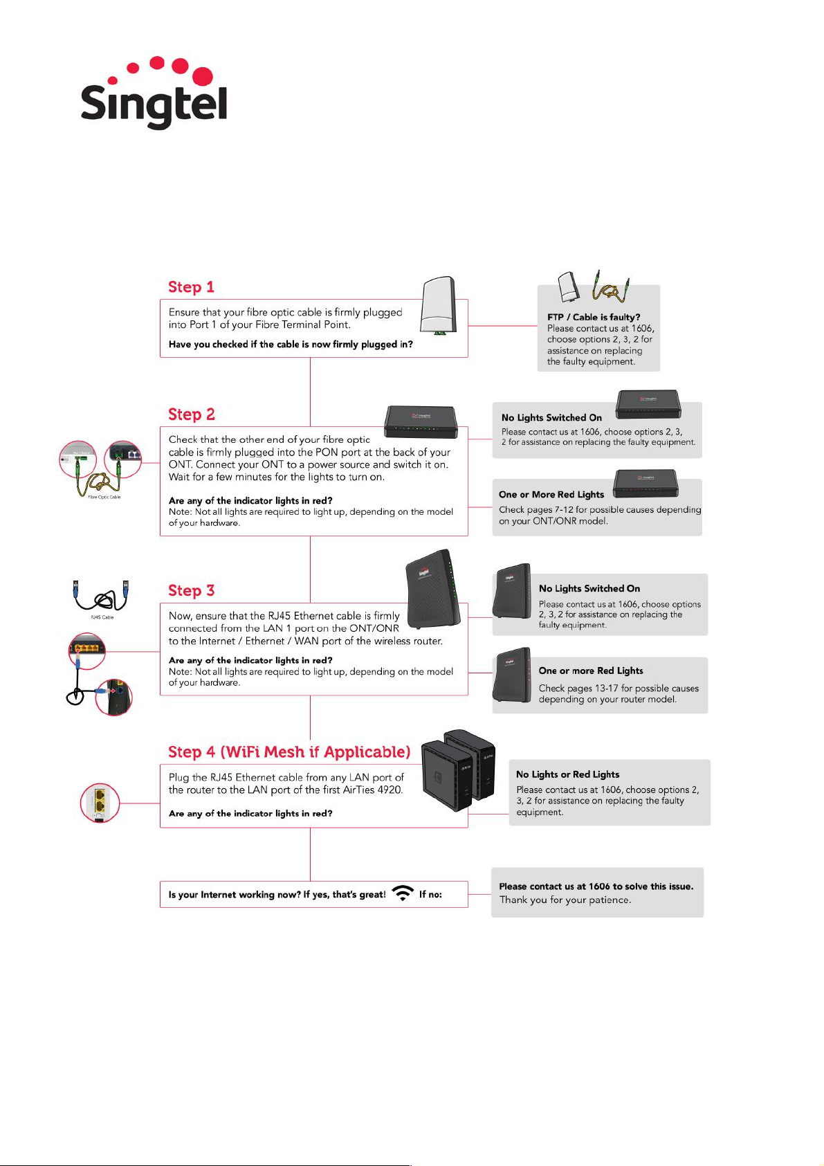
You may also refer to the following illustration to troubleshoot your network:
5
Connecting to Wireless/WiFi Network
Windows 7
Step 1
On the right hand side of the taskbar, click on the Wireless Network icon.
Step 2
A list of available networks will be displayed. Locate and select your wireless network (e.g.
SINGTEL(5G)-8992), the name of your wireless network can be found on your router. Tick the “Connect
automatically” box and you will not need to re-enter the network security key during your next connection
to the same wireless network. Click on the Connect button to initiate login.
Step 3
Enter your network security key in the “Security Key” field and click on the OK button. You can find
the default network security key on your Singtel modem or wireless router.
Step 4
On the “Set Network Location” window, click on Home Network.
Step 5
Click on the Close button to complete the setup and close the window.
Step 6
Once the wireless network is successfully connected, the bars of the Wireless Network icon will be
lit according to the network strength. A full bar indicates a strong signal.
Windows 8
Step 1
Bring up the Charms Bar by moving your mouse cursor to the lower right corner of the screen.
Step 2
Click on Settings > Network icon.
Step 3
A list of available networks will be displayed. Locate and select your wireless network (e.g.
SINGTEL(5G)-8992), the name of your wireless network can be found on your router.
• Ensure that the Airplane Mode is Off.
• Tick the “Connect automatically” box and you will not need to re-enter the network security key
during your next connection to the same wireless network.
• Click on the Connect button to initiate login.
Step 4
Enter your network security key and click on the Next button. You can find the default network
security key on your Singtel modem or wireless router.
Step 5
If you are prompted to turn on sharing, choose "Yes, turn on sharing and connect to devices".
Step 6
Once the wireless network is successfully connected, the bars of the Wireless Network icon will be
lit according to the network strength. A full bar indicates a strong signal.

6
Windows 10
Step 1
Click the Start button and click Settings from the Start menu.
Step 2
Click the Settings app’s Network & Internet icon, which opens to show your available wireless
networks.
Step 3
Choose to connect to the desired network by clicking its name and clicking the Connect button (e.g.
SINGTEL(5G)-8992). The name of your wireless network can be found on your router. Ensure that the
Airplane Mode is Off.
Step 4
Enter a password if needed. If you try to connect to a security-enabled wireless connection, Windows
will prompt you to enter a network security key. Your network security key can be found on your modem or
wireless router.
Step 5
Choose whether you want to share your files with other people on the network. If you’re connecting
on your own home or office network, choose “Yes, turn on sharing and connect to devices.” That lets you
share files with others and connect to shared devices, such as printers.
Step 6
Once the wireless network is successfully connected, the bars of the Wireless Network icon will be lit
according to the network strength. A full bar indicates a strong signal.
7
Optical Network
Terminal (ONT)
Model Guide
Please follow the guide according to the model of your ONT. To reboot your ONT,
simply unplug and plug the power adapter connected to your ONT hardware.
Current available models:
Model
Model Name
Page
Ericsson T063
5
ALU I-240G-D
6
ALU C-240C
7
Huawei GPON ONR HG8244H
8
ZTE F620G
9

8
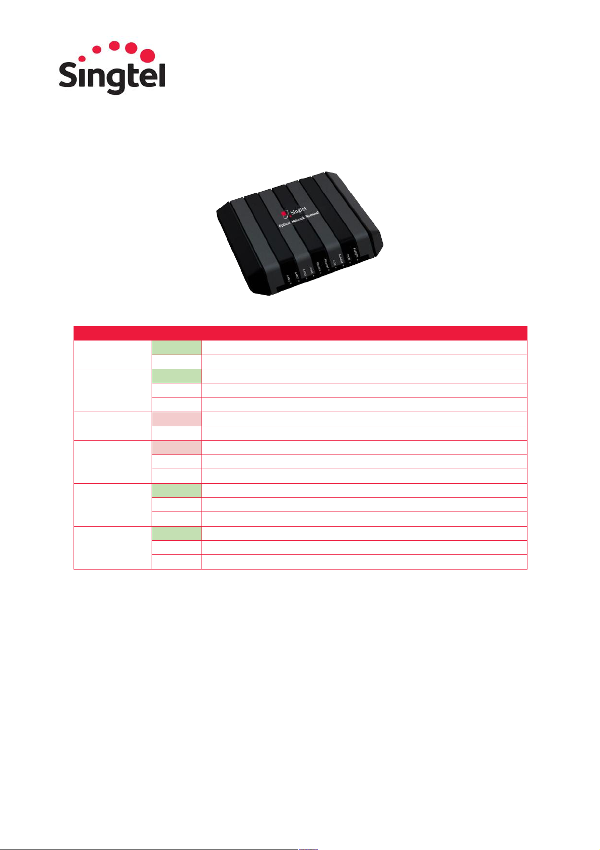
Ericsson T063:
LED Name
Status
Description
Power / Alarm
Green
DC Power is available to the ONT.
Amber
Error Condition / Alarm Condition
Note:
LED will be amber during ONT boot up. Amber LED will be cleared
upon completion of boot up sequence. LED will also be amber during
software upgrade operation. Amber LED will be cleared upon ONT
reboot post software upgrade process.
Off
There is no DC power at the ONT.
If power is provided, but this state persists:
• Ensure that the power cable connector is correctly seated in
the ONT power output
• Verify that the power supply adapter is plugged into a live AC
outlet or UPS
PON
Green
GPON handshake complete and OMCI link to the OLT is established.
Flashing
The OMCI link is being established.
Off
No OMCI link established or OMCI link setup in progress. This is
normal at boot-up and can take up to two minutes to turn green.
If this state persists, contact 1606, choose option 2, 3, 2.
LAN
Green
LAN port connectivity established on any of the 4 ports. Individual
LAN port activity LED resides on RJ45 socket at rear of ONT.
Off
No LAN port connectivity detected on all LAN ports.
Phone 1-2
Green
Voice phone line 1 is on-hook.
Off
Voice phone line 1 is on-hook.

9
ALU I-240G-D:
LED Name
Status
Description
Power
Green
Operating on AC power.
Flashing
Operating on battery power.
Off
ONT power is off.
OPTICAL /
PON
Green
Optical module normal; synchronized.
Flashing
PON optical port synchronization.
Off
PON optical port is not synchronized.
Red
Optical module power or signal loss. Please contact 1606.
LAN
Green
ONT local RJ-45 Ethernet interface connection is established.
Flashing
Ethernet data link transceiver.
Off
Ethernet interface is not connected.
UPDATE
Red
Upgrade failed. Please contact 1606.
Flashing
Upgrading
Off
No LAN port connectivity detected on all LAN ports.
ALM
Green
Local access.
Off
Normal state.
Red
Hardware exceptions. Please contact 1606.
POTS
Green
Off hook.
Flashing
Off hook for more than one hour.
Off
On hook.

10
ALU C-240C:
LED Name
Status
Description
Power
Green
Operating on AC power.
Flashing
Operating on battery power.
Off
ONT power is off.
OPTICAL /
PON
Green
Optical module normal; synchronized.
Flashing
PON optical port synchronization.
Off
PON optical port is not synchronized.
Red
Optical module power or signal loss. Please contact 1606.
LAN
Green
ONT local RJ-45 Ethernet interface connection is established.
Flashing
Ethernet data link transceiver.
Off
Ethernet interface is not connected.
UPDATE
Red
Upgrade failed. Please contact 1606.
Flashing
Upgrading
Off
No LAN port connectivity detected on all LAN ports.
ALM
Green
Local access.
Off
Normal state.
Red
Hardware exceptions. Please contact 1606.
POTS
Green
Off hook.
Flashing
Off hook for more than one hour.
Off
On hook.

11
Huawei GPON ONR HG8244H:
LED Name
Status
Description
POWER
Green
The ONR is powered on.
Off
The power supply is cut off.
Blinking Red
Hardware self-check failed or failed to start.
Blinking Red twice
then Stable Green
Uploading firmware.
PON
Green
Fibre connection is up.
Off
Fibre connection is down.
Blinking
Fibre connection set up in progress.
Red
Optical signals are abnormal, please reconnect the fibre
port. Contact service provider if the problem is not
resolved. Please contact 1606.
TEL 1 – TEL 2
Green
Corresponding voice service is up.
Blinking
Voice service is up and the phone is off-hook or ringing.
Off
Voice service is down or not available.
LAN 1 – LAN 4
Green
Ethernet connection is in normal state.
Blinking
Data is being transmitted on the Ethernet port.
Off
Ethernet connection is not set up.
USB
Green
USB port is connected and is working in the host mode,
but no data is transmitted.
Blinking
Data is being transmitted on USB port.
Off
USB port is not connected.
INTERNET
Green
Internet service is OK.
Blinking
Internet data is being transmitted.
Off
Internet service is down.
IPTV
Green
IPTV WAN IP address and STB detected OK.
Blinking
No IP address obtained in IPTV interface and STB
detected OK.
Off
No STB detected.
12
ZTE F620G:
LED Name
Status
Description
Power
Green
The ONT power is on.
Off
The ONT power is off.
PON
Green
The ONT is registered successfully.
Blink
The ONT is in the process of registration.
Off
The ONT failed to be registered or the system is not on.
LOS
Red
The ONT is receiving optical signals abnormally. Please contact 1606.
Off
The ONT is receiving signals normally.
ALARM
Red
The ONT is inactive or in fault. Please contact 1606.
Blink
Software download/upgrade in progress.
Off
The ONT is in normal operation.
LAN 1 - 4
Green
The network interface is connected but no data is transmitted.
Blink
Data is being transmitted or received.
Off
The device is not powered ON or data cable is not connected.
Phone 1-2x
Green
The device is registered on the SS but no data is transmitted.
Blink
Data is transmitted.
Off
The device is not powered ON or fails to register on SoftSwitch.

13
Singtel Wireless
Router Model Guide
Please follow the guide according to the model of your wireless router.
Current available models:
Model
Model Name
Page
Aztech DSL8900GR(AC)
9
Arcadyan Router AC2800
10
Arcadyan Mesh Router
12
14
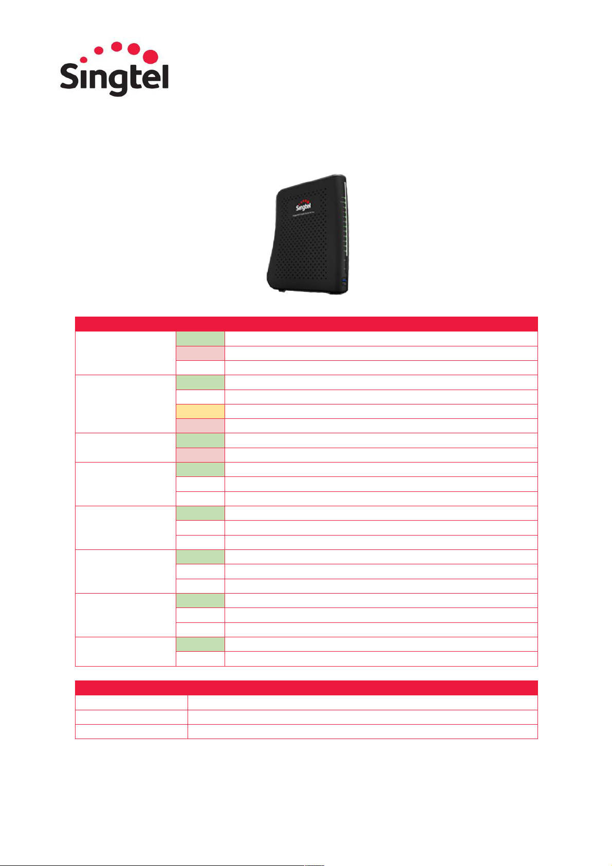
Aztech DSL8900GR(AC):
Front Panel Indicators & Buttons
Back Panel Ports & Button
• Power
• Ethernet LAN Ports 1 to 4
• 5GHz
• 2.4GHz
• USB
• Broadband (ADSL and Ethernet WAN)
• Internet
• WPS Indicator and Button
• USB 1
• USB 2
• Ethernet LAN Ports 1 to 4
• Ethernet WAN Port
• ADSL Port
• Reset Button
• Power Adapter Jack
15
Arcadyan Router AC2800:
LED Name
Status
Description
Power
Green
Router is receiving power.
Red
System failure. Please contact 1606.
Off
Power off.
Internet
Green
WAN connection is functioning correctly.
Red
Internet connection failure.
Amber
4GPP service has been detected and in use.
Red
No Internet link. Please contact 1606.
IPTV
Green
Set-Top Box connection has been established.
Red
No link. Please contact 1606.
LAN (1 – 4)
Green
Ethernet connection has been established.
Flashing
The indicated LAN port is sending or receiving data.
Off
No LAN connection on the port.
USB
Green
USB connection has been established.
Flashing
The indicated USB port is sending or receving data.
Off
No USB connection on the port.
2.4GHz
Green
2.4GHz Wireless link has been established.
Flashing
Data is being transmitted via wireless network.
Off
No wireless link.
5GHz
Green
5GHz Wireless link has been established.
Flashing
Data is being transmitted via wireless network.
Off
No wireless link.
WPS (Wi-Fi
Protected Setup)
Green
WPS link has been successfully established.
Off
The WPS is disabled.
Items
Description
WPS Button
Press this button for at least 6 seconds when activating the WPS function.
LED Button
Use this button to enable/disable the LED indicator light.
USB Port
Connect your USB (storage or mobile dongle) device to the USB port.

16
The router also supports the following ports and one reset button on the rear panel:
Items
Description
LAN Ports
Gigabit Ethernet ports (RJ-45). Connect devices on your local area
network to these ports (i.e., a PC, hub, or switch).
Internet (WAN) Port
Gigabit Ethernet port (RJ-45). Connect your Ethernet PPPoA/PPPoE link to
this port.
Reset Button
Use this button to reset the Router and restore the default factory settings.
To reset without losing configuration settings, refer to the Reboot settings
below.
Power Inlet
Connect the included power adapter to this inlet. Using the wrong type of
power adapter may cause damage.
To reboot:
Steps
Description
Step 1
Press the Reboot button to refresh the Router.
Step 2
Click OK to reboot the device.
Step 3
The reboot will be complete when the screen prompts for login.
Note: If you use the reset button on the back panel, the Router performs a power reset. If
the button is pressed for over 6 seconds, the factory default settings will be restored. Please
ensure that you have noted down your previous settings before resetting the router.

17
Arcadyan Mesh Router:
LED Name
Status
Description
Power
White
System is powered.
Flashing
FW is being upgraded.
Red
System fail. Please contact 1606.
Internet
White
Internet service is on.
Flashing
Getting IP address or No IP address.
Off
No WAN Ethernet connected.
LAN
White
One of the Ethernet LAN cable is linked.
Off
No Ethernet LAN cable is linked.
Mesh
White
Mesh connected – Good.
Flashing
Mesh is being paired.
Red
Mesh connected – Bad. Please contact 1606.
Off
No Mesh paired.
Steps
Description
Step 1
Plug the power adapter into the power socket on the rear of the Router, and
the other end into a power outlet.
Step 2
Use RJ-45 cable to connect from port 1 of the ONT device and the other end
to the ETHERNET or INTERNET WAN port (depending on your Router model).
Step 3
Use RJ-45 cables to
connect any of the four LAN ports on the Router and an Ethernet adapter on
your PC.
Step 4
If needed, you can use a 4G dongle to plug in the USB port.
Popular Network Hardware manuals by other brands

Bosch
Bosch VIP X1600 Module Installation and operating manual

JDS Uniphase
JDS Uniphase IP Video Test Option HST-3000 Specifications

CORNING
CORNING Everon 6000 v1.0 user manual

Paradyne
Paradyne COMSPHERE 3800PLUS release note

Infolock
Infolock INSIGHT DLP SENSOR 0910S Hardware installation guide

Burg Wächter
Burg Wächter SNVR-11612 Quick installation guide


