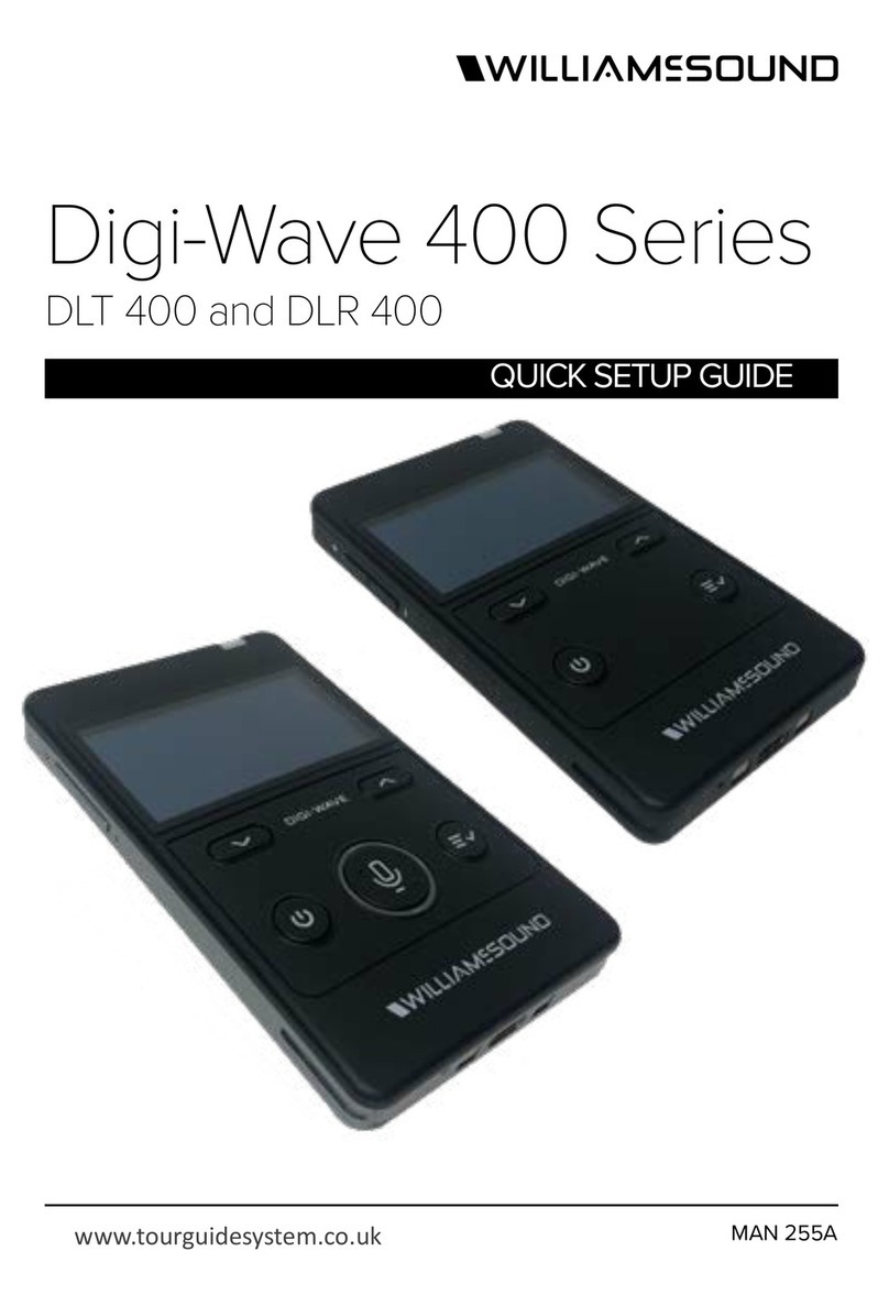
Sinosun 1510 Series Instruction Manual

1510 /2510 /4510 Series
150/220/450MHz Bands DataTransceivers
Installation and Operation Guide
Board Version
25Watt Enclosed Version
05-3624A01, Rev. B
JANUARY 2001
2Watt Enclosed Version

QUICK START GUIDE
Below are the basic steps for installing the transceiver. Detailed instructions are given in “Installation
Steps” on page 6 of this guide.
1. Mount the transceiver (see
Figure 6
or
Figure 7
for mounting dimensions)
2. Install and connect the antenna system to the radio
• Use only good quality, low loss coaxial cable.Keep the feedline as short as possible.
• Preset directional antennas in the direction of desired transmission/reception.
3.Apply DC power to the radio (10–30 Vdc@ 500 mA for RF 2W minimum)
• Measure the voltage source before connection.
• Observe proper polarity.
• Connect power to the power connector.
4. Set the radio’s basic configuration with a terminal (PC or HHT) connected to
the
INTERFACE
port
• Pin 23 of the INTERFACE port must be grounded to place the radio in the control and programming
mode. (See
Figure 12 on page 16
for a cable wiring diagram.)
• Set the transmit frequency (
TX xxx.xxx
).
• Set the receive frequency (
RX xxx.xxx
).
• Set/verify the data rate using the
BAUD
command.The default setting is
BAUD 9600 8N1
. (Refer to
“TRANSCEIVER PROGRAMMING” on page 14 for command details.)
5. Connect the data equipment to the radio’s INTERFACE connector
• Connection to the radio must be made with a DB-25 Male connector. Connections for typical sys-
tems are shown below.
• Connect only the required pins.Do not use a straight-through RS-232 cable with all pins wired.
• Verify the data equipment is configured as DTE. (By default, the radio is configured as DCE.)
6. Verify proper operation by observing the LED display
• See Table 5 on page 13 for a description of the status LEDs.
• Refine directional antenna headings for maximum receive signal strength using the
RSSI
command.
DB-25 DB-25
TRANSCEIVER
(DCE)
RTU
(DTE)
DB-9 DB-25
DB-9 to DB-25 ExampleDB-25 to DB-25 Example
2
3
2
3
TXD
RXD
TXD
RXD
GND GND
77
TRANSCEIVER
(DCE)
RTU
(DTE)
NOTE: Additional connections may be
needed in some installations.
See nstallation for details.
2
3
3
2
RXD
TXD
RXD
TXD
GND GND
57

60000] .......................................................................20
255] .....................................................................................20
BAUD [xxxxx abc].............................................................................20
FFFF FFFF] ....................................................19
255].....................................................................19
4.4 Detailed Command Descriptions ...................................................19
Error Messages................................................................................17
Entering Commands.........................................................................17
4.3 Keyboard Commands .....................................................................17
1.1 Differences Among Models ................................................................1
Handheld Terminal (HHT)...............................................................14
PC inTerminal Mode......................................................................14
05-3624A01, Rev. B i
TABLE OF CONTENTS
1.0 INTRODUCTION .........................................................................1
Modem Speeds ..................................................................................2
Frequency Coverage ..........................................................................2
1.2 Applications ......................................................................................2
Point-to-Multipoint, Multiple Address Systems (MAS)........................2
Point-to-Point System.........................................................................3
Switched Carrier Operation................................................................4
Single Frequency (Simplex) Operation...............................................4
1.3 Model Number Codes ......................................................................4
1.4 Accessories ......................................................................................5
2.0 INSTALLATION............................................................................6
2.1 Installation Steps ..............................................................................6
2.2 Mounting the Transceiver .................................................................8
Transceiver Board...............................................................................8
Enclosed Transceiver..........................................................................8
2.3 Antennas and Feedlines ..................................................................9
Antennas ............................................................................................9
Feedlines............................................................................................9
2.4 Power Connection ..........................................................................10
Conservation (Sleep Mode)..............................................................11
2.5 Data Interface Connections ............................................................11
3.0 OPERATION..............................................................................13
3.1 Initial Startup ..................................................................................13
3.2 LED Indicators ................................................................................13
4.0 TRANSCEIVER PROGRAMMING ............................................14
4.1 Radio Programming Methods ........................................................14
PC with Radio Configuration Software ..........................................14
4.2 PC Connection and Startup ...........................................................14
ADDR [NONE | 1–
AMASK [0000 0000–
CTS [0–
CTSHOLD [0–

7.0 GLOSSARY OF TERMS............................................................33
6.5 dBm-Watts-Volts Conversion Chart ................................................32
guration Software.................................................31
s Software .....................................................30
6.3 Helical Filter Adjustment ................................................................29
6.2 Bench Testing Setup ......................................................................29
cations ......................................27
6.0 TECHNICAL REFERENCE .......................................................27
nitions.....................................................................26
Major Alarms vs. Minor Alarms.........................................................26
STAT command.............................................25
5.2 Event Codes ...................................................................................25
5.1 LED Indicators ................................................................................25
5.0 TROUBLESHOOTING...............................................................25
TX [xxx.xxx]......................................................................................24
255 | ON | OFF]...................................................................24
STAT .................................................................................................24
SREV................................................................................................23
SER..................................................................................................23
255] ...................................................................23
RX [xxx.xxx]......................................................................................23
RSSI and RSSI!................................................................................23
PWR [L | M | H].................................................................................22
OWN [XXX...]....................................................................................22
OWM [XXX...] ...................................................................................22
KEY ..................................................................................................22
INIT...................................................................................................21
DKEY................................................................................................21
DEVICE [DCE | CTS KEY] ...............................................................21
6.1 x510 Series
ii 05-3624A01, Rev. B
RXTOT [NONE | 1–
TOT [1–
Checking for Alarms—
Event Code Defi
Transceiver Specifi
6.4 Upgrading the Radio’
Using Radio Confi

05-3624A01, Rev. B iii
Copyright Notice
This Installation and Operation Guide and all software described herein
are protected by
copyright: 2001 Wireless Data Systems Inc
. All
rights reserved.
Wireless Data Systems Inc. reserves its right to correct any errors and
omissions in this publication.
Antenna Installation Warning
1. All antenna installation and servicing is to be performed by
qualified technical personnel
only. When servicing the antenna, or
working at distances closer than those listed below,
ensure the
transmitter has been disabled.
2. Typically, the antenna connected to the transmitter is a directional
(high gain) antenna, fixed-mounted on the side or top of a building,
or on a tower. Depending upon the application and the gain of the
antenna, the total composite power could exceed 90 watts EIRP. The
antenna location should be such that only qualified technical per-
sonnel can access it, and that under normal operating conditions no
other person can touch the antenna or approach within
2.3 meters
of
the antenna.
ISO 9001 Registration
Wireless Data Systems adheres to this internationally accepted
quality system standard.
RF Exposure
Separation distances
required for FCC RF
Exposure compliance
Antenna Gain vs. Recommended Safety Distance
(x510 Series)
Antenna Gain (EL705 OEMSeries)
0–5 dBi 5–10 dBi 10–16.5
dBi
Minimum RF
Safety Dis-
tance
0.6 meter 1.06 meters 2.3 meters

iv 05-3624A01, Rev. B
Quality Policy Statement
We, the employees of Wireless Data Systems Inc., are committed to
understanding and exceeding our customer’s needs and expectations.
•We appreciate our customer’s patronage. They are our business.
•We promise to serve them and anticipate their needs.
•We are committed to providing solutions that are cost effective,
innovative and reliable, with consistently high levels of quality.
•We are committed to the continuous improvement of all of our
systems and processes, to improve product quality and increase
customer satisfaction.
FM/UL/CSA Notice
This product is available for use in Class I, Division 2, Groups A, B,
C & D Hazardous Locations. Such locations are defined in Article 500
of the National Fire Protection Association (NFPA) publication NFPA
70, otherwise known as the National Electrical Code.
Thetransceiver hasbeen recognizedforuse inthese hazardouslocations
by three independent agencies —Underwriters Laboratories (UL), Fac-
tory Mutual Research Corporation (FMRC) and the Canadian Standards
Association (CSA). The UL certification for the transceiver is as a Rec-
ognized Component for use in these hazardous locations, in accordance
with UL Standard 1604. The FMRC Approval is in accordance with
FMRC Standard 3611. The CSA Certification is in accordance with
CSA STD C22.2 No. 213-M1987.
FM/UL/CSA Conditions of Approval:
The transceiver is not acceptable as a stand-alone unit for use in the haz-
ardous locations described above. It must either be mounted within
anotherpiece ofequipmentwhich iscertifiedfor hazardouslocations,or
installed within guidelines, or conditions of approval, as set forth by the
approving agencies. These conditions of approval are as follows:
1. The transceiver must be mounted within a separate enclosure which
is suitable for the intended application.
2. The antenna feedline, DC power cable and interface cable must be
routed through conduit in accordance with the National Electrical
Code.
3. Installation, operation and maintenance of the transceiver should be
in accordance with the transceiver's installation manual, and the
National Electrical Code.
4. Tampering or replacement with non-factory components may
adversely affect the safe use of the transceiver in hazardous loca-
tions, and may void the approval.

05-3624A01, Rev. B v
5. When installed in a Class I, Div. 2, Groups A, B, C or D hazardous
location, observe the following:
WARNING —EXPLOSION HAZARD—
Do not disconnect
equipment unless power has been switched off or the area is known
to be non-hazardous.
Refer to Articles 500 through 502 of the National Electrical Code
(NFPA 70) for further information on hazardous locations and approved
Division 2 wiring methods.
ESD Notice
(Board version only)
To prevent malfunction or damage to this product, which may be caused
by Electrostatic Discharge (ESD), the radio should be properly
grounded at the time of installation. In addition, the installer or main-
tainer should follow proper ESD precautions, such as touching a bare
metal object to dissapate body charge, prior to touching components or
connecting/disconnecting cables.
Cable Length Recomendation
We recommends a maximum cable length of 3.0 meters for
DC power
and
data
connections to this product.
Revision Notice
While every reasonable effort has been made to ensure the accuracy of
this manual, product improvements may result in minor differences
between the manual and the product shipped to you. If you have addi-
tional questions or need an exact specification for a product, please con-
tactour CustomerServiceTeam usingtheinformation atthe backof this
guide. In addition, manual updates can often be found on the our Web
site at
www.sinosun.cn.
.
Distress Beacon Warning
In the U.S.A., the 406 to 406.1 MHz band is reserved for use by distress
beacons. Since the 4710A radio is capable of transmitting in this
band, take precautions to prevent the radio from transmitting between
406to 406.1 MHz.Thisnotice applies
only
to 4710A Transceivers
used in the U.S.A.

All x510 Series
x510 Series
x510 Series
05-3624A01, Rev. B 1
1.0 INTRODUCTION
This guide presents installation and operating instructions for the
of digital radio transceivers. The radios can be purchased
as compact, modular boards for direct mounting inside remote terminal
units (RTUs), programmable logic controllers (PLCs), automatic
banking machines, or similar equipment. They are also available as
standalone units packaged in their own enclosures (see lower cover
illustration).
Although this manual focuses on the board-level product, the operating
specifications and user connections are identical for both versions of the
radio. Only the visual appearance and mounting details differ between
the two. These differences are explained in the text where necessary.
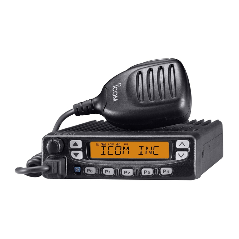
The transceiver (Figure 1) is a data telemetry radio designed to operate
in a point-to-multipoint environment, such as electric utility
Supervisory Control and Data Acquisition (SCADA) and distribution
automation, gas field automation, water and wastewater SCADA, and
on-line transaction processing applications. The radio employs
microprocessorcontroltoprovide highly reliablecommunications, even
under adverse conditions.
radios use continuous-phase frequency shift
keying (CPFSK) modulation. Domestic models employ a 4-level
modem; ETSI models, a 2-level modem.
Invisible place holder
Figure 1. OEM Series™ Series Data Transceiver
(Board version shown—enclosed unit similar)
1.1 Differences Among Models
models are very similar in appearance and
functionality. The major differences are over-the-air modem speed and
frequency coverage.

X510 Series radios are available for operation in the 200 MHz or 400
205-3624A01, Rev. B
Modem Speeds
Domestic models are capable of 9600 bps transmission over the air;
ETSI models, 4800 bps. This does
not
affect the local
DATA INTERFACE
port speed, which will accept asynchronous data between 1200 and
19200 bps.
Frequency Coverage
MHz frequency bands. The exact frequency coverage of each model is
listed in the Specifications chart on Page 26.
NOTE:
The radio’s frequency range (band) cannot be set or changed
by the user; it is set at the factory.
1.2 Applications
Point-to-Multipoint, Multiple Address Systems (MAS)
Point-to-multipoint (MAS) is the most common application of the
transceiver. It consists of a central master station and several associated
remote units as shown in Figure 2. An MAS network provides
communications between a central host computer and remote terminal
units (RTUs) or other data collection devices. The operation of the radio
system is “transparent”to the computer equipment. That is, the radio
system transports the data in its original form, making no changes to the
data format.
Often, the radio system is used to replace a network of remote monitors
currently linked to a central location by leased telephone lines. At the
central office of such a system, there is usually a large mainframe
computer and some means of switching between individual lines
coming from each remote monitor. In this type of system, there is a
modulator/demodulator (modem) at the main computer and at each
remote site, usually built into the remote monitor itself. Since the cost of
leasing a dedicated-pair telephone line is quite high, radio is frequently
used as an alternative communication medium.

05-3624A01, Rev. B 3
Invisible place holder
Figure 2. MAS Point-to-Multipoint Network
(Two remote stations shown—four or more are typically used)
Point-to-Point System
Where permitted, the transceiver may also be used in a point-to-point
arrangement.
A point-to-point system consists of just two radios—one
serving as a master and the other as a remote—as shown in Figure 3. It
provides a simplex or half-duplex communications link for the transfer
of data between two locations.
Invisible place holder
Figure 3. Typical Point-to-Point Link
radio
HOST
COMPUTER
MASTER
STATION
RTU
radio
REMOTE
RTU
radio
REMOTE
radio
HOST
COMPUTER
MASTER
STATION
RTU
radio
REMOTE

X510 Series
X510 Series
405-3624A01, Rev. B
Switched Carrier Operation
Switched Carrier operation is a half-duplex mode where the master
station transmitter is keyed to send data and unkeyed to receive.
radios operate in switched carrier mode and are keyed
when data is present.
NOTE:
radios do not support full-duplex
operation (i.e., transmitting and receiving at the same time).
For information on other products that provide this
capability, contact your sales representative.
Single Frequency (Simplex) Operation
Single frequency operation (also known as simplex) is a special case of
switched carrier operation. Single frequency operation is
automatically
selected whenever the transmit and receive frequencies are set to the
same value.
1.3 Model Number Codes
The radio model number is printed on the PC board or on the radio
enclosure, and provides key information about how the radio was
configured when was shipped from the factory. See Figure 4 for an
explanation of the model number characters.
Invisible place holder
Figure 4. 1510/2510/4510 Series Model Number Codes
THIS INFORMATION IS
SUBJECT TO
CHANGE.
DO NOT USE FOR
PRODUCT ORDERING.
EL705
BAND SUB-BAND
2 = 200 MHz A = 220240 MHz
4 = 400 MHz A = 330355 MHz
B = 355380 MHz
C = 380400 MHz
D = 400420 MHz
E = 420450 MHz
F = 450470 MHz
G = 480512 MHz
H = 406430 MHz
BANDWIDTH
1 = 12.5 kHz Domestic
2 = 12.5 kHz ETS
ENC OSURE
0 = Without Enclosure
1 = With Enclosure
SAFETY
N = None
C = CE Mark
MODEM
2 = 4800 BPS
3 = 9600 BPS
AGENCY
E = ETS
F = FCC/ C
N = None
NA N

05-3624A01, Rev. B 5
1.4 Accessories
The transceiver can be used with one or more of the accessories listed in
Table 1. Contact the factory for ordering information.
Table 1. Optional Accessories
Accessory Description P/N
Hand-Held Terminal
Kit (HHT) Keypad terminal for programming,
diagnostics, and control. Includes
carrying case, cable set and an
instruction booklet. (Accessory Power
Adapter 03-3722A01 required for use
with OEM radios—see below).
02-1501A01
Accessory Power
Adapter DB-25 male-to-female adapter that
attaches to the radio’s DATA
INTERFACE connector. Provides
regulated10 Vdc forpowering anHHT
or other low power accessory. If not
used, accessories could be damaged
by excessive voltage (equal to the
radio’s DC input voltage).
03-3722A01
RTU Simulator Assy. Test unit that simulates data from a
remote terminal unit. Comes with
polling software that runs on a PC.
Used for testing OEM radio operation.
(NOTE: Older MDS RTU Simulators
will
not
work with the OEM radio as
they require a higher input voltage.)
03-2094A01
DB-9 to DB-25adapter Used to connect a PC with a 9-pin
serial port to the radio’s DATA
INTERFACE port.
01-3683A01
Radio Configuration
Software (EL705) Radio programming software for use
with a Windows-based PC. This
programis available on3.5”disks, and
is included on the MDS’InSite 6.4 (or
higher) CD.
03-3649A01
PC Programming
Adapter Kit Requiredwhenprogrammingtheradio
with a personal computer operating in
terminal mode. The adapter asserts
the auto-open signal (ground) on pin
23 of the DATA INTERFACE port. A
scratch-built cable may also be used
for this purpose (see Figure 12 on
Page 16).
01-3683A01

x510 Series
605-3624A01, Rev. B
2.0 INSTALLATION
There are three main requirements for installing the transceiver—
adequate and stable primary power, a good antenna system, and the
correct data connections between the transceiver and the data device.
Figure 5 shows the external connections for the transceiver.
Invisible place holder
Figure 5. External Connections to the Transceiver Board
(Connector locations identical to enclosed radio)
2.1 Installation Steps
Below are the basic steps for installing the transceiver. In many cases,
these steps alone are sufficient to complete the installation. More
detailed explanations appear at the end of these steps.
1. Mount the transceiver to a stable surface using the appropriate
hardware.
2. Install the antenna and antenna feedline for the station. Preset
directional antennas in the desired direction of transmission and
reception.
3. Measure and install the primary power for the radio. The primary
power must be between 10 and 30 Vdc and be capable of supplying
at least 600 milliamperes. (600 mA requirement assumes a 2 watt
RF output. Lower current consumption is possible if lower output
power may be used in your application—see
Transceiver Specifications on Page 26 for details.)
NOTE: Use the radio in negative ground systems only.

05-3624A01, Rev. B 7
4. Set the radio configuration. The transceiver is designed for quick
installation with a minimum of software configuration in most cases.
The selections that must be made or verified for new installations
are:
•Transmit frequency
•Receive frequency
•Network address (factory-set to NONE)
The operating frequencies are not set at the factory unless they are
specified at the time of order. Determine the transmit and receive
frequencies to be used, and follow the steps below to program them.
5. Connect a terminal interface (personal computer or a hand-held
terminal) to the DATA INTERFACE connector. (See PC Connection
and Startup on Page 14 for details.)
6. Press to receive the ready “>”prompt.
a. Set the transmit frequency with theTX xxx.xxx command.
Press after the command.
b. Set the receive frequency with the RX xxx.xxx command.
Press after the command.
c. Set the network address with the ADDR xxx command.
Press after the command. After programming, the
terminal interface reads PROGRAMMED OK to indicate successful
entry.
7. Disconnect the terminal interface from the DATA INTERFACE
connector.
8. Connect the data equipment to the transceiver’s DATA INTERFACE
connector. Use only the required pins for the application—do not
use a fully pinned (25 conductor) cable. Basic applications often
require only the use of Pin 2 (Transmitted Data—TXD), Pin 3
(Received Data—RXD), and Pin 7 (Signal Ground).
Additional connections may be required in some installations. Refer
to the complete list of pin functions in Table 4 on Page 11.
ENTER
ENTER
ENTER
ENTER

Transceiver (25W) Mounting Dimensions (Enclosed Version)
805-3624A01, Rev. B
2.2 Mounting the Transceiver
Transceiver Board
Figure 6 shows the mounting dimensions of the transceiver PC board.
The board should be secured to the mounting surface using the holes
provided at each corner of the assembly. (Fasteners are not supplied.)
Note that the lower left mounting hole in the board is a threaded ferrule.
Invisible place holder
Figure 6. Transceiver Mounting Dimensions (Board Version)
Enclosed Transceiver
Figure 7 shows the mounting dimensions of the enclosed transceiver.
Two cutout slots are provided on each side of the enclosure for
mounting screws. (Fasteners are not supplied.)
RF DATA PWR
4.53 in.
(11.51 cm)
0.23 in.
(0.86 cm)
3.23 in.
(8.20 cm)
0.28 in.
(0.71 cm)
3.73 in.
(9.47 cm)
0.28 in.
(0.71 cm) 0.20 in.
(0.51 cm)
4.05 in.
(10.29 cm)
HEATSINK
2.5 in.
(6.35 cm)
1”in.
(2.54 cm)
HEATSINK HEIGHT: 0.38”(0.97 cm)
5.625"
143 mm
2.25"
57 mm
2.0"
50 mm
8.5"
1.75"
4.44 CM
6.63"
168 mm
2.75"
70 mm
7.25"
184 mm
ALTERNATE
POSITION

Figure 7. Transceiver (2W) Mounting Dimensions (Enclosed Version)
05-3624A01, Rev. B 9
2.3 Antennas and Feedlines
Antennas
The transceiver can be used with a number of antennas. The exact style
depends on the physical size and layout of the radio system. Suitable
antennas are available from several manufacturers.
At master stations, omni-directional antennas (Figure 8) are typically
used to provide equal coverage to all remote sites in the network.
Invisible place holder
Figure 8. Typical Omni-directional Antenna for Master Stations
(Shown mounted to mast)
At remote sites, a directional Yagi (Figure 9) or corner reflector antenna
is generally recommended to minimize interference to and from other
users. Invisible place holder
Figure 9. Typical Yagi Antenna for Remote Sites

).
10 05-3624A01, Rev. B
Tables 2and 3show the losses that occur when using various lengths
and types of cable at 200 and 400 MHz, respectively. Regardless of the
type of cable used, it should be kept as short as possible to minimize
signal loss.
2.4 Power Connection
The transceiver can be operated from any well-filtered 10 to 30 Vdc
power source. The power supply must be capable of providing at least
600 milliamperes if 2 watt output is planned. Supply the power to the
power connector (see Figure 5 on Page 6
Do not power the radio through Pin 18 of the DB-25 Interface
connector, as this does not provide over-current input protection for the
radio. Pin 18 is intended only as an auxiliary output for powering a
low-current (1.0 Amp max.) device, such as an RTU.
NOTE: The radio is designed for use in negative ground systems only.
Table 2. Length vs. Loss in Coaxial Cables at 200 MHz
Cable Type 3 Meters
(10 Feet) 15 Meters
(46 Feet) 30 Meters
(91 Feet) 150 Meters
(525 Feet)
RG-8A/U 0.32 dB 1.6 dB 3.2 dB 16 dB
1/2 inch HELIAX 0.10 dB 0.49 dB 0.98 dB 4.9 dB
7/8 inch HELIAX 0.05 dB 0.27 dB 0.54 dB 2.7 dB
1-1/4 inch HELIAX 0.04 dB 0.20 dB 0.40 dB 2.0 dB
1-5/8 inch HELIAX 0.03 dB 0.17 dB 0.33 dB 1.65 dB
Table 3. Length vs. Loss in Coaxial Cables at 400 MHz
Cable Type 10 Feet
(3.05 Meters) 50 Feet
(15.24 Meters) 100 Feet
(30.48 Meters) 500 Feet
(152.4 Meters)
RG-8A/U 0.51dB 2.53 dB 5.07 dB 25.35 dB
1/2 inch HELIAX 0.12 dB 0.76 dB 1.51 dB 7.55 dB
7/8 inch HELIAX 0.08 dB 0.42 dB 0.83 dB 4.15 dB
1-1/4 inch HELIAX 0.06 dB 0.31 dB 0.62 dB 3.10 dB
1-5/8 inch HELIAX 0.05 dB 0.26 dB 0.52 dB 2.60 dB
CAUTION
POSSIBLE
EQUIPMENT
DAMAGE
Feedlines
The selection of antenna feedline is very important. Poor quality cables
should be avoided as they result in power losses that may reduce the
range and reliability of the radio system.

(modem) and is normally connected to an EIA-232/485 device. The
05-3624A01, Rev. B 11
Conservation (Sleep Mode)
In some installations, such as at solar-powered sites, it may be necessary
to keep the transceiver’s power consumption to an absolute minimum.
This can be accomplished by configuring the data device (RTU, PLC,
etc.)to ground Pin12of the DATAINTERFACEconnector, whichremoves
power from the radio. When the ground is removed, the radio is ready
to operate within 75 milliseconds.
2.5 Data Interface Connections
The transceiver’s DATA INTERFACE connector is configured as a DCE
transceiver supports over-the-air asynchronous data rates up to
19200 bps. Refer to Figure 10 and Table 4 for a detailed description of
each pin on the DATA INTERFACE connector.
Do not use a 25 wire (fully pinned) cable for connection to the DATA
INTERFACE connector. Use only the required pins for the application.
Damage may result if improper connections are made. For EIA-232
signaling, typical applications require the use of Pins 2, 3, and 7 only.
Invisible place holder
Figure 10. Data Interface Connector Pinouts
(As viewed from the front of the radio)
CAUTION
USE
ONLY REQUIRED
PINS
1
13
25 14
Table 4. DATA INTERFACE Connector Pinouts
Pin
Number Input/
Output Pin Description
1--Protective Ground. Connects to ground (negative supply
potential) on the radio’s PC board and chassis.
2INTXD—Transmitted Data. Accepts TX data from the
connected device.
3 OUT RXD—Received Data. Outputs received data to the
connected device.
4INRTS—Request-to-Send Input. Causes CTS to go
“high.”
5 OUT CTS—Clear-to-Send Output. Behavior depends on
DEVICE command setting:
When DEVICE is set to DCE, this pin follows RTS and will
provide “buffer full”flow control.
When DEVICE is set to CTS KEY, this pin provides a
keyline output when receive data is present.

12 05-3624A01, Rev. B
6 OUT DSR—Data Set Ready. Active when radio is powered on.
7--Signal Ground. Connects to ground (negative supply
potential) at radio’s PC board.
8 OUT DCD—Data Carrier Detect. Active when receiving
data from another OEM Series radio with the same
network address.
11 OUT Receive Audio Output. For test purposes only.
12 -- Sleep Mode. A logic low on this pin removes power from
the radio. The radio is ready to operate 75 milliseconds
after the ground is removed.
18 IN/OUT Accessory Power. Unregulated Output. Provides a
source of output power for low current (1 Amp max.)
accessories. Excessive drain on this connection causes
the on board fuse (2 ampere) to open. The voltage at this
pin matches the input voltage to the transceiver. Do not
use this pin for powering the radio.
19 OUT 5.8 Vdc Regulated Output. Provides a source of
regulated voltage at 100 mA for low power accessories.
23 IN Auto-Open. A logic low (less than 0.5 volts or ground)
on this pin opens the diagnostic channel and disables
normal data operation. A logic high (greater than 4 volts or
open) enables the DATA INTERFACE for normal data
operation.
25 OUT Alarm. Alogic low(less than0.5 volts) on this pinindicates
normal operation. A logic high (greater than 4 volts)
indicates that some alarm condition is present. This pin
can be used as an alarm output, provided the internal
series resistance of 1 kΩis considered.
Table 4. DATA INTERFACE Connector Pinouts (Continued)
Pin
Number Input/
Output Pin Description
20 485+
____________________________________________________________________
22 485-

05-3624A01, Rev. B 13
3.0 OPERATION
In-service operation of the transceiver is completely automatic. Once
the unit has been properly installed and configured, operator actions are
limited to observing the radio’s LED status indicators for proper
operation.
3.1 Initial Startup
If all parameters are set correctly, operation of the radio can be started
with these steps:
1. Apply DC power to the transceiver.
2. Observe the LED status panel for the proper indications (see
Table 5).
3. If not done earlier, refine the antenna heading of the station to
maximize the received signal strength (RSSI) from the master
station. Use the RSSI command from a terminal interface connected
to the radio’s DATA INTERFACE connector.—See Section 4.0,
TRANSCEIVER PROGRAMMING.
3.2 LED Indicators
The transceiver includes four status LEDs visible from the top of the
unit,behind theData Interface connector.Table 5 describes thefunction
of each status LED.
RXDTXDDCDPWR
Table 5. LED Status Indicators
LED Name Description
PWR
(Power) •Continuous—Power is applied to the radio, no problems
detected.
•Rapid flash (five times-per-second)—Fault indication.
•Flashing once every second—Unit is not programmed. Radio is
in Bootloader mode.
DCD
(Data Carrier
Detect)
Flashing—Indicates another radio (with the same network
address) is transmitting at the radio’s receive frequency.
RXD
(Receive Data) Receive data is present on DATA INTERFACE connector.
TXD
(Transmit Data) Transmit data is present on DATA INTERFACE connector.
This manual suits for next models
2
Table of contents
