Sioux Tools PRO-TEC PONY Series User manual

64', 70' TRUSS WALL BUILDING
36' PONY WALL SINGLE TUBE BUILDING 36' PONY WALL TRUSS BUILDING
PRO-TEC AWNING SYSTEMS
MANUAL NO. 187297
/ 08/31/2009
REV B/MRS 8/8/17 E N 17-141
42', 56' TRUSS WALL BUILDING
42', 56', 64', 70' PONY WALL TRUSS BUILDING

Dear Sentry Building Owner,
We would like to take this opportunity to thank you for purchasing a SIOUX
STEEL PRO-TEC BUILDING. We believe that it will serve you well for many
years. The framework uses quality certified structural grade steel tubing. All
welded rafter assemblies are powder coated or hot-dipped galvanized to provide
maximum corrosion protection. We believe in providing QUALITY, RELIABILITY,
DURABILITY, VERSATILITY, and COMMITMENT to meet the needs of our
customer. Should you have any questions or comments during or following the
installation, please feel free to call your SIOUX STEEL PRO-TEC BUILDING
dealer or manufacturer. We will be glad to assist you in any way we can.
IMPORTANT
Improper Site Preparation, Assembly and Maintenance may invalidate warranty
and cause unnecessary and costly mistakes.
READ MANUAL FIRST
If you have any questions contact
Sioux Steel Co. at 1-800-557-4689
Procedure For Viewing Sentry Manuals On-Line:
•Log on to siouxsteel.com.
•Select Dealer Login in upper right hand corner.
•Enter Username, Password and select Submit.
If you don t have a username and password, contact your dealer or
Sioux Steel Company Customer Service at 1-800-557-4689.
•Select the Engineering Manuals folder in the center of the screen.
•Select the ProTec Manuals folder.
•Select the Sentry folder.
•Based on manual description select the desired manual you wish to open, view
and/or print.
•A second tab will open up with a PDF file of the desired manual.
•If you wish to print the manual, select the printer icon in the upper left hand
corner.

GENERAL INFORMATION
Foundation for Sentry Building:
In all cases, the soil and foundation must be sufficiently stable and deemed suitable to support the
forces produced by the structure. It is recommended that the customer consult a qualified
engineer to certify the soil conditions and foundation design for their location. Soil and
foundation must be able to withstand forces which meet or exceed the structural forces. Contact
Sioux Steel Company or your dealer for building specific structural forces.
Site Conditions for Sentry Building:
The installation site must be sufficiently level to permit uniform wall assembly on a support
foundation. In all cases, the area surrounding the Sentry Building must provide sufficient
drainage to prevent soil erosion around the foundation. The structure has been designed to meet
90 mph exposure C wind load and 30, 40, and 50 psf (16', 12', & 10' rafter spacing
respectively) ground snow load, for open terrain with obstructions having heights generally less
than 30 feet. This terrain must extend upwind for a distance greater than 2600 feet. The building
must be positioned at least 20 feet away from existing structures with a higher eave to prevent
excessive load from drifting snow.
Contact your insurance agent prior to assembly to insure you are covered in case of
inadvertent accidents that may occur during erection.
NOTE: Sioux Steel Company is not responsible or liable for:
- Any damage or failure that may occur due to incorrect erection of building.
- Any soil analysis or foundation design,
- Substitution of components not specified in the construction manual that lead to
damage or failure.
- Unstable soil conditions or foundation that lead to structure damage or failure.
- Damage caused by leaning sidewalls.
- Any modification of design or structure.
- Any bodily injury that occurs during the assembly of the building or as a
result of modification to the design or improper construction.
- Caustic or corrosive environments that lead to structure deterioration, damage or
failure.
- See warranty in structure manual.

REF - RAFTER TUBE
7
3
4
5
8
3
3
3
2
4
6
6
REF - POST
1
AWNING FRAME PARTS LISTING
36' PW SINGLE TUBE BUILDING
ITEM NUMBER DESCRIPTION QTY
1 179947GRY AWNING END TUBE, LH 1
2 179948GRY AWNING END TUBE, RH 1
3 179720GRY AWNING CENTER TUBE VAR
4 179758GRY EAVE SWAGED END TUBE 2
5 172328GRY EAVE DOUBLE SLIP TUBE 1
6 172329GRY EAVE SINGLE SLIP TUBE VAR
7 177962GRY LOWER TUBE VAR
8 177964GRY LOWER BRACE TUBE VAR
2

172329GRY
EAVE- SINGLE SLIP TUBE
179947GRY
END TUBE, LH
177964GRY
LOWER BRACE
AWNING COMPONENTS
36' PONY WALL SINGLE TUBE BUILDING
179948GRY
END TUBE, RH
179758GRY
EAVE- SWAGED END TUBE
177962GRY
LOWER TUBE
179720GRY
CENTER TUBE
172328GRY
EAVE- DOUBLE SLIP TUBE
3

154029
BOLT, 3/8" X 3-1/2"
AWNING COMPONENTS
36' PONY WALL SINGLE TUBE BUILDING
169706
BOLT, 3/8" X 1-1/2"
154051
HEX NUT, 3/8"
167834
LAGSCREW, 5/16" X 3"
187299
DRILL SCREW, 1/4" X 3/4"
4

27-1/2
these holes
shown and align
Position parts as
Use (8) 5/16 x 3 lag bolts
at each post
27-1/2
Use (8) 5/16 x 3 lag bolts
at each post
Position parts as
shown and align
these holes
Right End Post Detail
Left End Post Detail
Center Post Detail
Attach the 177962GRY Lower Tubes to posts as shown below using (4) 167834 5/16 x 3 lag bolts.
Note the brace positions for each post location.
Attach the 177964GRY Lower Braces to the posts by aligning the single hole with the
lower tube and attching its mount plate to the posts using (4) 167834 5/16 x 3 lag bolts.
INSTALLATION OF BRACE TUBES
36' PONY WALL SINGLE TUBE BUILDING
27-1/2
these holes
shown and align
Position partsas
Use (8) 5/16 x 3 lag bolts
at each post
5
frame members
10' Center to
Center for awning
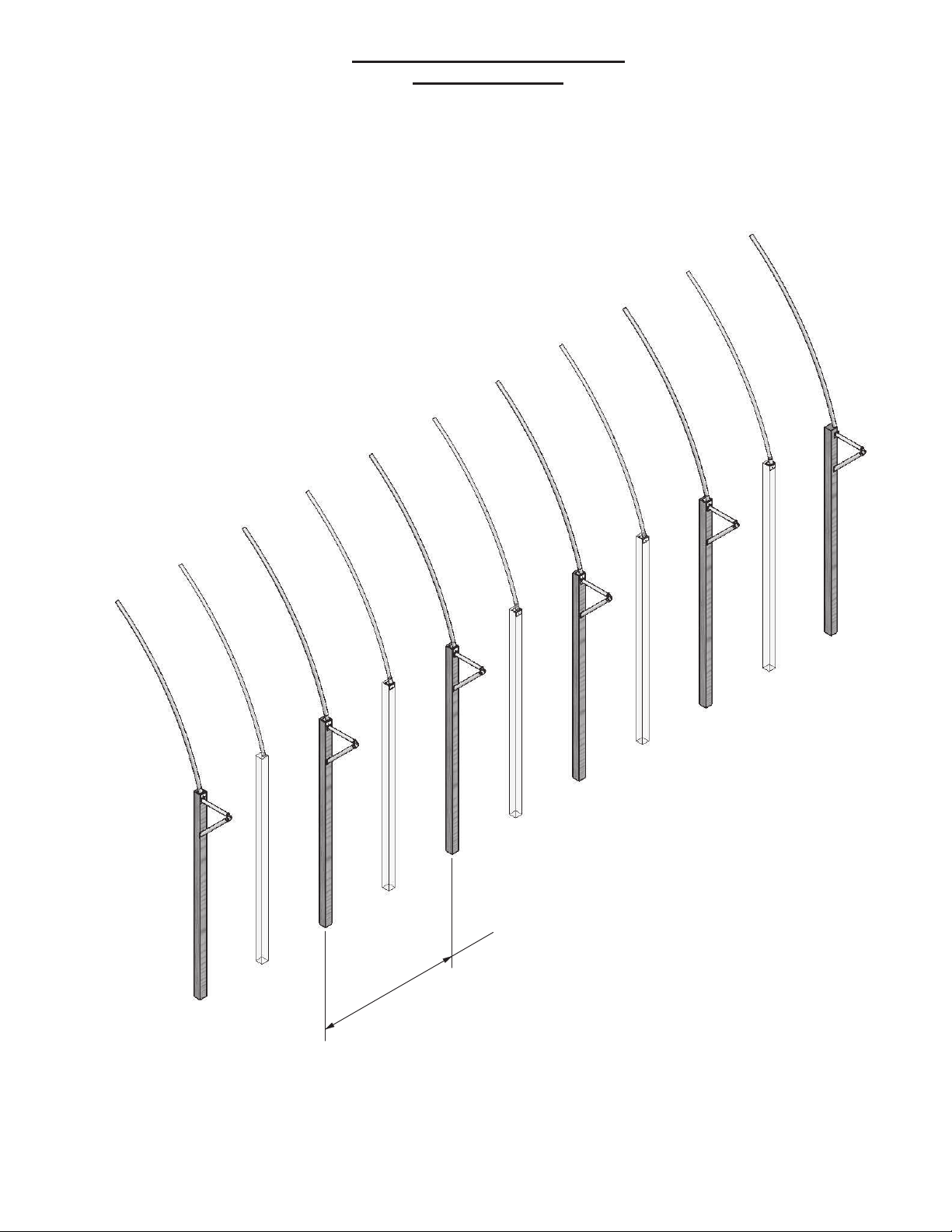
Install the Lower Tubes and Lower Braces on every other post per the diagrams
on the preceeding page. The spacing of the Awning frame members is
10' on centers.
BRACE TUBE INSTALLATION
OVERALL VIEW
36' PONY WALL SINGLE TUBE BUILDING
6

179947GRY
179948GRY
are installed
Leave this connection
loose untill the slide tubes
179720GRY
Attach 179947GRY End Tube, LH to the Brace Tubes using 3/8 x 1-1/2 bolts and nuts.
Attach the other end to the rafter tubes by drilling a 7/16 dia hole (use the Awning tube bracket
as a guide) and secure with 3/8 x 3-1/2 bolts and nuts.
Attach 179720GRY Center Tubes to the Brace Tubes using 3/8 x 1-1/2 bolts and nuts.
Attach the other end to the rafter tubes by drilling a 7/16 dia hole (use the Awning tube bracket
as a guide) and secure with 3/8 x 3-1/2 bolts and nuts.
Attach 179948GRY End Tube, RH to the Brace Tubes using 3/8 x 1-1/2 bolts and nuts.
Attach the other end to the rafter tubes by drilling a 7/16 dia hole (use the Awning tube bracket
as a guide) and secure with 3/8 x 3-1/2 bolts and nuts.
After this End Tube is attached to the rafter tube, remove the bolt from the brace connection
untill the Eave Swaged End Tube has been installed.
MAIN AWNING TUBES INSTALLATION
36' PONY WALL SINGLE TUBE BUILDING
Secure the End Tubes, Lower Tubes,
and Lower Braces with 3/8 x 1-1/2 bolts
and nuts.
at the second hole.
Preferred
Drill a 7/16 hole through
the rafter tube and secure
with 3/8 x 3-1/2 bolts and
nuts.
An alternate method would be to
secure with 3/8 x 3-1/2 bolts and nuts
Alternate
7

Install one end of 179758GRY Eave- Swaged Slip Tube into the 179947GRY Awning End Tube, LH.
The opposite end slides into 172328GRY Eave- Double Slip Tube. Slide the bungs of the Double
Slip Tubes into 179720GRY Awning Center Tubes. These parts are held in place with 187299
1/4 x 3/4 Drill Screws. Make sure to install the drill screws from the lower side of Awning tubes to
keep their heads away from the building cover.
Next slide 172329GRY Eave- Single Slip Tubes into the remaining Eave Tubes and the remaining
Awning Center Tubes and secure with the Drill Screws as before.
The last section is completed by inserting another 179758GRY Eave- Swaged Slip Tube between
the final Eave- Single Slip Tube and 179948 Awning End Tube, RH. Reinstall the 3/8 x 1-1/2 bolt
and nut at the last Brace Tubes and secure the last Slip Tube with Drill Screws as before.
AWNING SLIP TUBE INSTALLATION
36' PONY WALL SINGLE TUBE BUILDING
172329GRY
179947GRY
Installed Last
179948GRY
179758GRY
179758GRY
after last Slip Tube is installed.
172328GRY
172329GRY
Reinstall this 3/8 x 1-1/2 bolt and nut
179720GRY
8
This manual suits for next models
1
Table of contents


