Sirio Antenne OT Bioelettronica EMG-USB User manual
User manual v 1.42
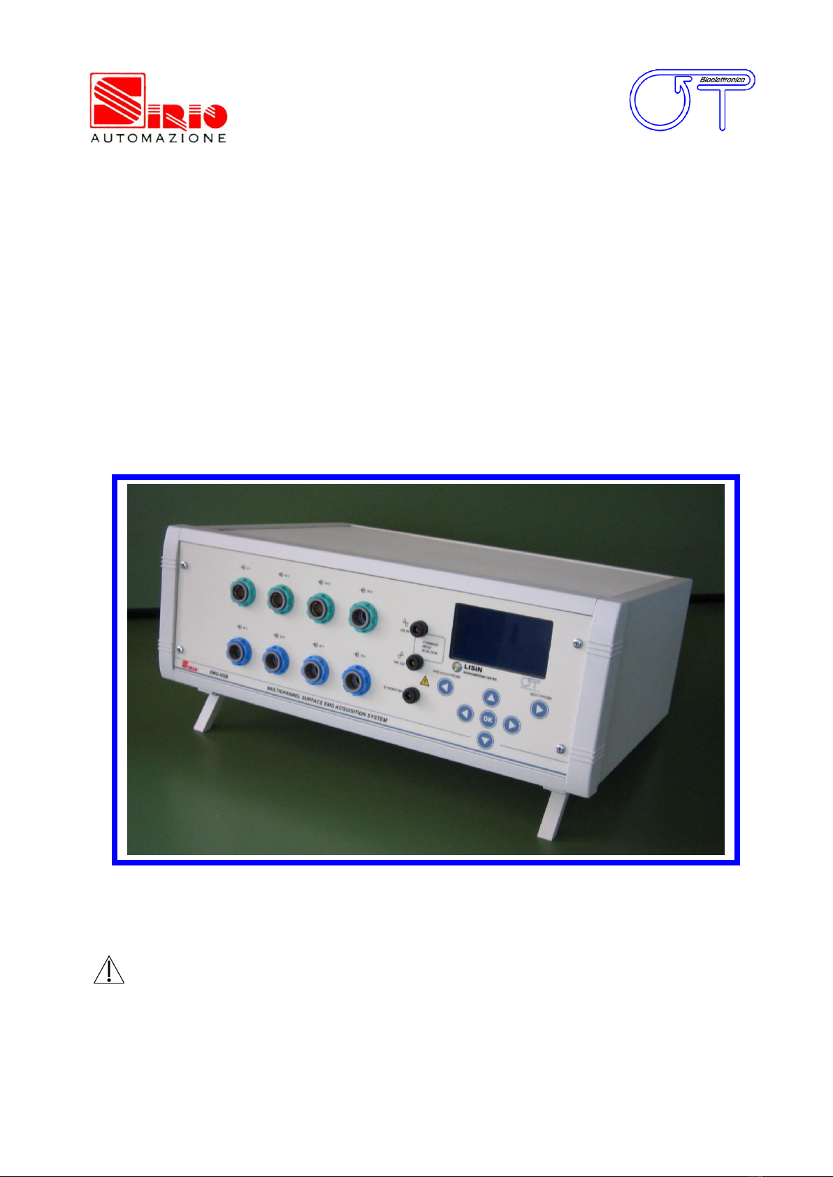
EMG-USB
electromyographic signal amplifier
Read this manual carefully before using the EMG-USB amplifier.

EMG-USB User manual v.1.42
pag. 2

EMG-USB User manual v.1.42
pag. 3
INDEX
1. GENERAL DESCRIPTION ......................................................................................pag. 5
2. EMG-USB KIT CONTENT .......................................................................................pag. 6
3. END USERS ...........................................................................................................pag. 6
CONTRAINDICATIONS ....................................................................................pag. 6
SIDE EFFECTS ................................................................................................pag. 6
4. SAFETY CAUTIONS AND OTHER WARNINGS ......................................................pag. 7
5. SYMBOLS USED ON EMG-USB AND IN THE USER MANUAL ...............................pag. 9
6. TECHNICAL SPECIFICATIONS ..............................................................................pag. 10
7. DETAILED DESCRIPTION......................................................................................pag. 12
FRONT PANEL
.............................................................................................pag. 12
IN connectors........................................................................................pag. 12
PATIENT REF plug ................................................................................pag. 13
DRL IN plug .........................................................................................pag. 13
DRL OUT plug ......................................................................................pag. 14
Liquid crystal display and keypad............................................................pag. 15
REAR PANEL
...............................................................................................pag. 17
Power supply connector .........................................................................pag. 17
Power supply switch ..............................................................................pag. 17
Fuse box...............................................................................................pag. 18
Fan.......................................................................................................pag. 18
USB connector ......................................................................................pag. 18
AUXILIARY INPUTS ..............................................................................pag. 19
BLANKING INPUT connector ..................................................................pag. 19
TRIGGER INPUT connector ....................................................................pag. 19
8. USE OF THE ELECTROMYOGRAPH .......................................................................pag. 20
ELECROMIOGRAPH SETUP
........................................................................pag. 20
CONNECTION OF THE ACCESSORIES
.........................................................pag. 21
Neuromuscular stimulator .....................................................................pag. 21
PATIENT CONNECTION
..............................................................................pag. 22
MEASUREMENT EXECUTION
......................................................................pag. 25
Differential acquisition mode ..................................................................pag. 25
Monopolar acquisition mode...................................................................pag. 32
Acquisition during electrically elicited contractions ..................................pag. 33
9. TROUBLESHOOTING ............................................................................................pag. 35
10. EMG-USB MAINTENANCE AND STORAGE ..........................................................pag. 41
11. TECHNICAL CHARACTERISTICS.........................................................................pag. 42
12. WARRANTY ........................................................................................................pag. 43
WARRANTY CONDITIONS ...............................................................................pag. 43

EMG-USB User manual v.1.42
pag. 4

EMG-USB User manual v.1.42
pag. 5
1.
GENERAL DESCRIPTION
The EMG-USB electromyograph is a multichannel amplifier for surface electromyography (sEMG).
The EMG-USB electromyograph allows the acquisition and recording of the electric signals
generated by muscles during voluntary or electrically elicited contractions and detected by surface
electrode arrays applied on the skin. The signals acquired by the instrument are amplified, filtered
and converted into digital form and then transferred to a PC, via an USB interface, for real-time
visualization and storage.
The EMG-USB is a research instrument designed for clinical research carried out by qualified
researchers. It is not available for general use by unqualified users.
The EMG-USB is a modular system. It can amplify from 16 to 128 channels of sEMG in modules of
8 channels per board installed. The number of amplifier boards installed in the system determines
the total number of channels. Each amplifier board carries 8 sEMG channels. The total number of
analog inputs can be customized on user request in modules of 8 channels up to 128 channels.
Several configurations of electrodes are possible by means of a number of cable adapters that
allow splitting a block of 16 channels into groups of smaller number of channels.
Amplification boards other than sEMG amp-boards can be realized on user request to allow
external synchronous acquisition of other biological and non-biological signals (ECG, EEG, MMG,
force, etc.).
The EMG-USB instrument is completely safe for the patient. The safety is achieved by means of
medical grade electrical insulation of all the circuitry connected to the patient.
This user manual refers to all hardware versions of the instrument.

EMG-USB User manual v.1.42
pag. 6
2. EMG-USB KIT CONTENT
1 EMG-USB surface EMG amplifier with 16N channels (N = 1 to 8)
1 to 8 cable adapters with one 16 electrodes array for EMG signal detection (depending on
the number of channels installed into the amplifier);
1 conductive gel package;
3 reference straps;
Arrays and matrix of electrodes of different sizes, depending on the user request;
1 EMG-USB user manual.
3. END USER
EMG-USB surface EMG amplifier allows non-invasive recording of electromyographic signals
(sEMG) generated during voluntary or electrically elicited muscular contractions and detected by
surface electrode arrays or grids placed on the skin of the patient. The end user must be familiar
with the technique and must have received proper training in multichannel EMG detection and
interpretation.
Contraindications
EMG-USB has no particular contraindications when used jointly with neuromuscular stimulators or
personal computers, provided that all the electrical devices connected to it and the power line
comply with safety rules and standards concerning grounding and leakage currents.
Side effects
No significant side effects are known. The materials used for manufacturing all the parts in contact
with the patient are biocompatible. Possible slight cutaneous allergic reactions (e.g. skin
reddening) are reduced to a minimum during short duration electromyographic signal acquisitions.

EMG-USB User manual v.1.42
pag. 7
4. SAFETY CAUTIONS AND OTHER WARNINGS
The use of the EMG-USB surface electromyograph is absolutely forbidden in the following
conditions:
While other monitoring devices are in use with the patient.
While electro surgery equipment, short waves or microwaves therapy devices are used.
When other medical devices are used with the patient.
By mentally impaired people.
On patients not assisted by qualified staff (e.g. medical doctor or therapist).
Whenever the equipment is damaged.
In proximity of inflammable substances (especially inflammable liquids and gases) or in
environments with high concentration of oxygen.
On patients carrying life-supporting equipment that might be adversely affected by
electromagnetic interferences, such as pacemakers, etc.
The following cautions should be observed:
Only use electrodes supplied by the distributor: EMG-USB is guaranteed to achieve tested
performance only if used with electrodes supplied by the distributor.
Contact the distributor immediately if extraneous materials permeate into the device (liquids,
powders, etc.). In case of hard shocks suffered by the EMG-USB (like a drop to the floor, etc.),
verify that no crack or any other kind of damage of the box resulted from the shock. In case
of doubt, please contact the distributor.
The EMG-USB electromyograph is subject to electromagnetic interference that is not dangerous
for the patient (such as electrostatic or electromagnetic interference generated by electrical
motors and other sources). This interference may affect the measurements of the physiological
variables derived from the EMG signal. These measurements are not meant to be used for
diagnostic purposes, and thus these signal alterations cannot be dangerous for the patient,
please always take into account the presence of noise in your signal processing tasks and
evaluations.

EMG-USB User manual v.1.42
pag. 8
Before making any measurement, it is mandatory to check the quality of the grounding of the
power line to which the EMG-USB is connected. The use of electrical devices with
grounding connections not compliant with safety standards represents a high risk
for the patient and the operator.
The connection between EMG-USB and other electrical devices (e.g. a PC) must be done in
compliance with the European standard EN 60601-1-1 on medical devices.
Always use the EMG-USB with a PC manufactured in compliance with the European standards EN
60950 (safety standard for information technology devices), EN 55022 (EMC standard) and EN
55024 (immunity standard).
Electrical motors and other electrical devices (relay, remote control switch, neon lights, etc.)
near the EMG-USB electromyograph can be a source of electromagnetic interference that
disturbs the amplifier. The presence of such electromagnetic fields is not dangerous for the
patient, but can alter the electromyographic signals and cause unreliable measurements.
The use of the EMG-USB electromyograph by unskilled personnel is not a danger for the
patient, but it is discouraged. Only trained personnel with the proper clinical and physiological
knowledge can correctly discriminate between a valid measurement and an incorrect one.
Incorrect measurements can arise when unskilled personnel use the device in presence of
strong sources electromagnetic interference (e.g. strong electromagnetic fields). The presence
of interference in the signals is easily recognised by skilled personnel.
EMG-USB electromyograph is not designed to be portable equipment. Should it be necessary to
move the EMG-USB electromyograph, it must be properly packaged to avoid typical vibrations
and shocks arising from transportations. Vibrations could cause the release of metallic particles
inside the appliance, such as screws, nuts and bolts, that could compromise the safety of the
patient and the integrity of the appliance.
EMG-USB User manual v.1.42
pag. 9
5. SYMBOLS USED ON EMG-USB AND IN THE USER MANUAL
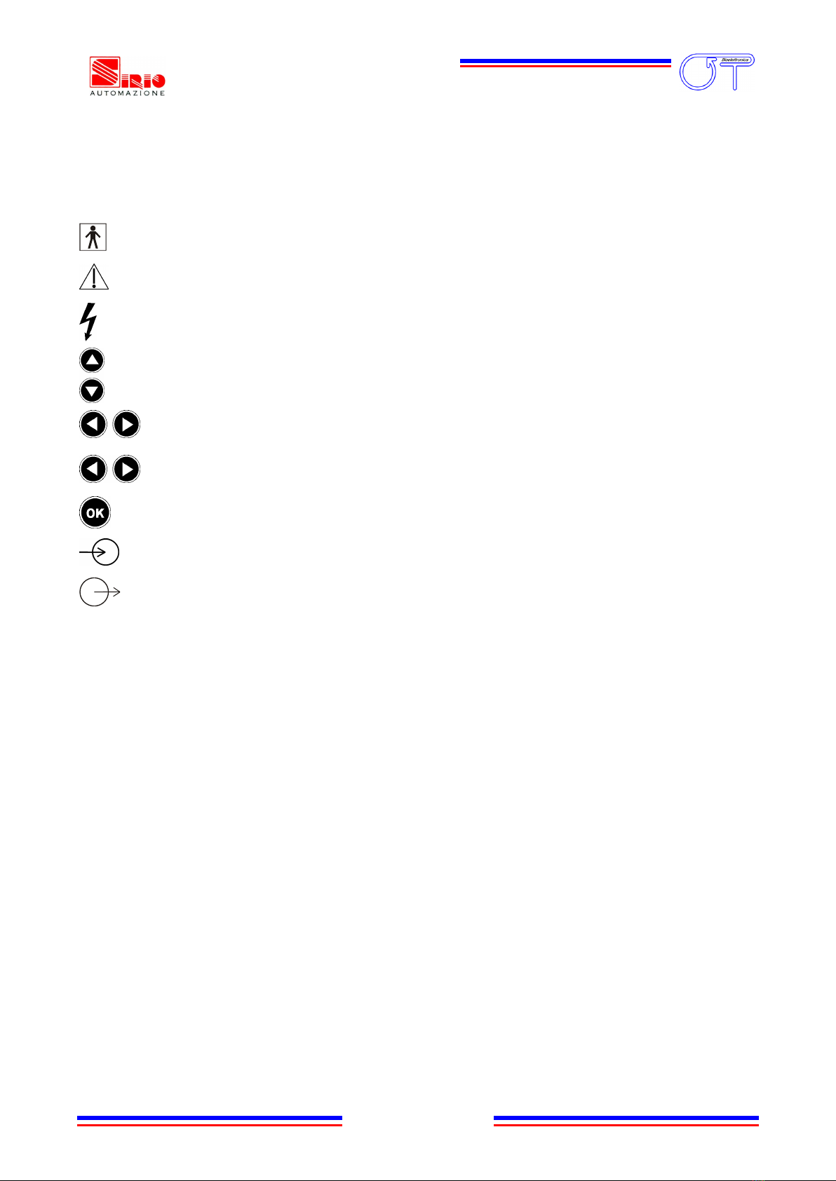
Class BF for circuitry applied to patient.
Read carefully the instruction remarks before use.
Dangerous voltage level, power line voltage.
Multifunction keys to select the parameter to be modified.
Multifunction keys to modify the selected parameter value.
Input selection keys, indicated as Previous probe and Next probe. They can be used to
select the group of channels related to an IN connector.
Multifunction key to enter the selected parameter value.
Signals input.
Signals output.
I O
Power on (I): switch on power line voltage supply.
Power off (O): switch off power line voltage supply.

EMG-USB User manual v.1.42
pag. 10
6. TECHNICAL SPECIFICATIONS
The EMG-USB electromyograph is an optically and galvanically insulated device designed to
guarantee a high safety level for the patient and the operator in all operating conditions. The
optical and galvanic insulation separates the circuitry connected to the patient from the circuitry
connected to external non-medical devices, such as the PC used for data acquisition and user
interface.
The EMG-USB electromyograph is designed to measure surface EMG signals in monopolar and
single differential mode during voluntary or electrically elicited contractions. An embedded
circuitry, called Driven Right Leg (DRL) circuitry, is available to reduce common mode voltage
noise arising from electrical interference from the power line. The DRL is particularly useful in
monopolar acquisition mode.
Surface EMG signals can be recorded with different configurations of electrode arrays.
TAB. 1 shows an example of possible probe configuration with a 128 channel EMG
electromyograph.
Number of electrodes in the array
Number of probes simultaneously available
128 electrodes
1 probe
64 electrodes
2 probes
16 electrodes
8 probes
8 electrodes
16 probes
4 electrodes
32 probes
TAB. 1: Examples of probe configurations with a 128-channel EMG-USB electromyograph. In version with a lower
number of channels, the number of probes decreases accordingly.
As shown in the example, it is possible to simultaneously acquire signals with different electrode
arrays. This is necessary when signals from different muscles need to be recorded at the same
time.
Using the front panel keypad, it is possible to choose the number of probes and assign a gain
value to each probe. When the signals are detected from different muscles (e.g. biceps brachii and
upper trapezius) it can be necessary to set different gain levels for each probe to exploit the full
range of the A/D converter and obtain the best possible recording of the signal. EMG-USB technical
specifications are shown in TAB. 2.

EMG-USB User manual v.1.42
pag. 11
EMG channels
Maximum input range
50 mVPP
Bandwidth
10 ÷ 750 Hz, 8th order Bessel band pass filter
Total noise (RTI)
< 0.8 VRMS (differential), < 1.3 VRMS (monopolar),
Selectable gain
OFF, 100, 200, 500, 1000, 2000, 5000, 10000 V/V
Input impedance
> 90 MΩ on the entire bandwidth
CMRR
> 96 dB (114 dB typical)
Cross talk between channels
<-50 dB (monopolar and differential)
Sample frequency
2048 Hz
A/D converter resolution
12 bit
A/D converter input dynamics
0 ÷ 5 V
Data transfer to PC
USB1.1 o USB2.0 interface
Insulation voltage
4.000 VDC
Auxiliary channels (optional)
Input range
± 5 V
Bandwidth
Channels are not filtered
Gain
0.5 V/V
Input impedance
200 kΩ
Sample frequency
2048 Hz
A/D converter resolution
12 bit
A/D converter input dynamics
0 ÷ 5 V
TAB. 2: EMG-USB technical specification

EMG-USB User manual v.1.42
pag. 12
7. DETAILED DESCRIPTION
FRONT PANEL
FIG. 1 shows controls, indicators and connectors present on the front panel of the EMG-USB and
described in the following sections.
FIG. 1: EMG-USB front panel
IN connectors
Each of the IN connectors is used to connect a 16 electrodes array adapter (mode:
Probes: 1x16CH), a double adapter for 8 electrodes arrays (mode: Probes: 2x8CH) or a
quadruple adapter for 4 electrodes arrays (mode: Probes: 4x4CH).
To enable the array adapters of interest, choose the Probes mode with the keypad and select the
menu value corresponding to the electrode arrays used. For detailed information on how to
change the EMG-USB settings, refer to the
Liquid crystal display and keypad
section.
Each adapter can be connected either to:
a standard array of silver bar electrodes (suitable to find the optimal position where to place
the array on the muscle and to perform short time isometric measurements)
an adhesive array (suitable for long duration signal acquisition and/or for acquisitions during
dynamic contractions).
EMG-USB
SURFACE EMG ACQUISITION SYSTEM
IN 1
IN 3
OK
IN
connectors
PREVIOUS PROBE
NEXT PROBE
IN 4
IN 7
IN 8
IN 2
IN 5
IN 6
PATIENT REF
DRL IN
DRL OUT
COMMON
MODE
REJECTION
R
DRL IN
connector
DRL OUT
connector
PATIENT REF
connector
Liquid crystal display
Keypad

EMG-USB User manual v.1.42
pag. 13
VERY IMPORTANT NOTICE:
For a correct signal recording it is necessary to connect the patient to the PATIENT_REF input of
the EMG USB. The connection is established by attaching a wet strip to the patient's body at a
point where there is NO MYOELECTRIC ACTIVITY (e.g. at the ankle or the wrist).
In monopolar acquisition mode (Mode: Monopolar) it is also necessary to connect another strip to
the DRL_IN input of the EMG-USB. The DRL_IN strip actually becomes both the common electrode
for the monopolar acquisition mode and the input to the DRL noise reduction circuitry. Also in this
case, the DRL_IN strip MUST BE CONNECTED to a point on the patient where there is NO
MYOELECTRIC ACTIVITY, usually close to the PATIENT_REF strip. It is mandatory to carefully
AVOID that the two strips touch each other. If the two strips touch each other, the DRL_IN
common electrode is shorted with the PATIENT_REF electrode and, in such a case, the whole
measurement session becomes INVALID.
In case of high levels of electromagnetic interference, it may be necessary to activate the DRL
noise reduction circuitry. To activate the DRL noise reduction circuitry a third strip MUST BE
connected at a point on the patient far from the PATIENT_REF and the DRL_IN strip, usually on
the other wrist or ankle. Be careful to place the DRL_OUT electrode in a way that the array of
electrodes result to be placed between the DRL_IN and the DRL_OUT electrodes. The DRL_OUT
electrode actually carries the cancellation signal. If the DRL_OUT electrode is not connected to the
patient, the whole DRL noise reduction circuitry is INACTIVE.
For further specifications refer to DRL_IN and DRL_OUT sections.
PATIENT_REF input
The PATIENT_REF input connects the EMG-USB reference point of the amplifier to the patient.
The reference point must be connected to a point on the patient's body without myoelectric
activity (e.g. the ankle or the wrist) using the supplied ground strip. The strip must be wet with
water to ensure a good electric contact with the patient.
REMARK: failure in connecting this electrode prevents the correct acquisition of the EMG signal.

EMG-USB User manual v.1.42
pag. 14
DRL_IN input
The DRL_IN input connects the common input of the amplifiers to the patient's body while in
monopolar acquisition mode, and is also used as the input to the DRL noise reduction circuitry.
The DRL_IN input is always used for signal acquisition in monopolar mode (Mode: Monopolar)
and for power line interference reduction as DRL input, if necessary, during differential acquisition
mode (in this case also the DRL_OUT must be connected to the patient to reduce the
interference). The electrode connected to this input is a conductive strip of the same type as the
one used for referencing the patient to the amplifier circuitry. The strip must be wet with water to
ensure a good electric contact with the patient and has to be attached to a point on the patient's
body without myoelectric activity (e.g. the ankle or the wrist), usually alongside the strip used
for the patient grounding. It is mandatory that the two strips DO NOT TOUCH EACH OTHER,
otherwise the signal is completely disrupted and the acquisition becomes nonsense.
REMARK: failure in connecting this electrode prevents the correct acquisition of the EMG signal in
monopolar mode (Mode: Monopolar).
DRL_OUT output
The DRL_OUT output connects the output of the DRL interference reduction circuitry to the
patient's body. The DRL_OUT output should be used during acquisition in monopolar mode
(Mode: Monopolar) in case of electromagnetic interference caused by electric engines, isokinetic
machines or other electrical devices working near the EMG-USB. A wet strip to ensure a good
electric contact with the patient must be connected at a point of patient's body in a way that the
electrode array will be between the DRL output and the DRL input. Placing the DRL output at the
opposite wrist or ankle with respect to the wrist or ankle bearing the DRL_IN strip usually satisfies
this requirement. It is not strictly required to connect this strip at a point without myoelectric
activity, whereas this is strictly required for the DRL_IN and PATIENT_REF.
REMARK: failure in connecting this electrode prevents the correct acquisition of the EMG signal in case
of high levels of electromagnetic interference.
EMG-USB User manual v.1.42
pag. 15
Liquid crystal display and keypad
The liquid crystal display is turned on when the EMG-USB amplifier is switched on. After an
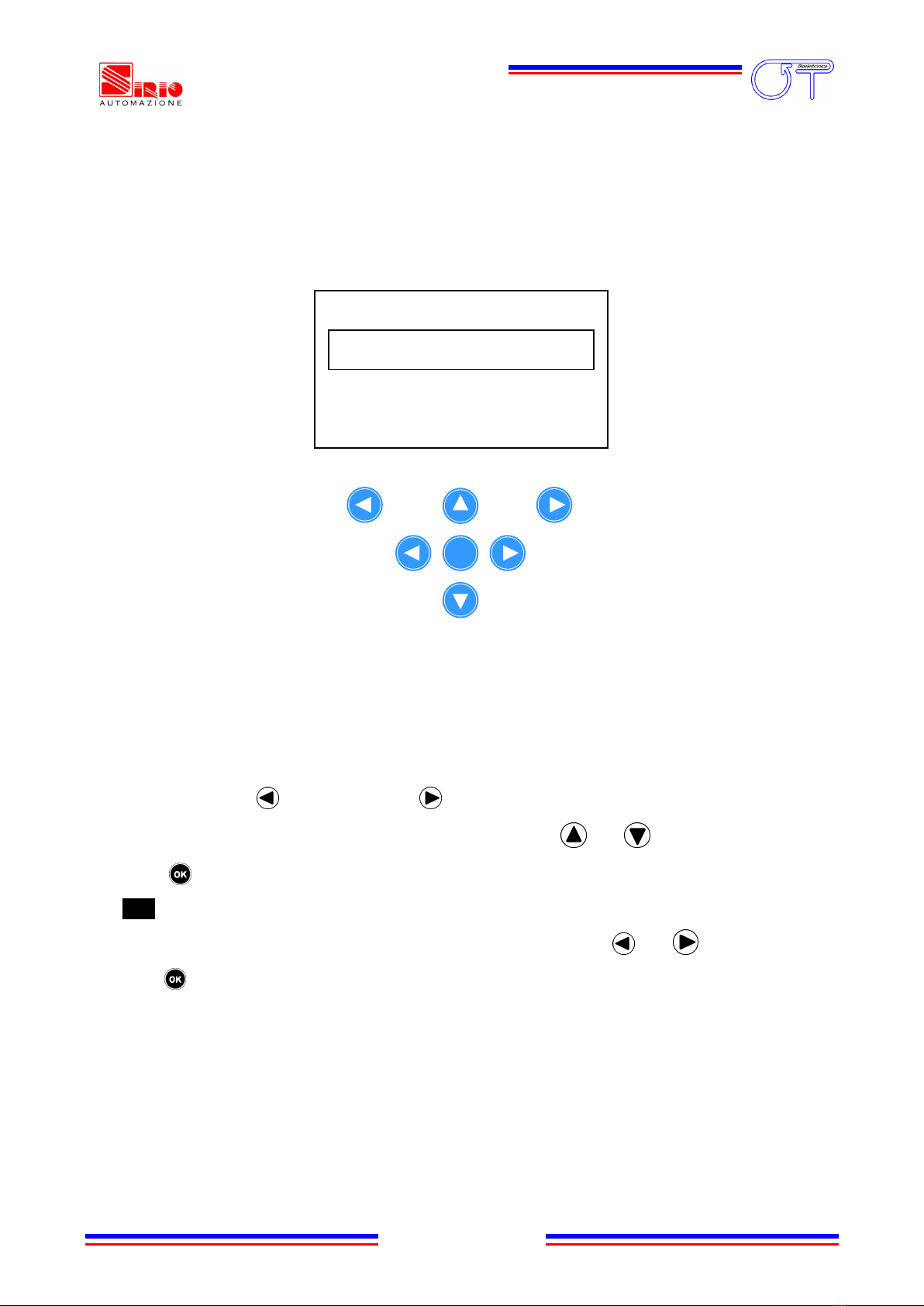
introducing screen-shot, the EMG-USB settings are presented as shown in FIG. 2.
FIG. 2: Example of a screen-shot of the liquid crystal display
The embedded keypad allows the operator to change the settings of EMG-USB amplifier as
explained in the following instructions:
A group of 16 channels related to one of the IN connectors can be selected using the
PREVIOUS PROBE and NEXT PROBE keys.
Move the arrow ( ) on the desired parameter using the and keys.
Press to confirm the selection of the parameter. The arrow will be displayed in negative
() to indicate that it is possible to change the value of the selected parameter.
Scroll the available options and select the desired value using the and keys.
Press to confirm the new value.
The selectable options for each programmable parameter of the EMG-USB amplifier are listed
below in TAB. 3:
Probe 1: 4x4CH
G1: 500 G2: 5k
G3: 100 G4: 20k
Mode: Differential
OK
PREVIOUS PROBE
NEXT PROBE

EMG-USB User manual v.1.42
pag. 16
Parameter
Description
Available options
Probe
EMG input probe configuration: 16-electrode array probe, double
8-electrode array probe or quadruple 4-electrode array probe can
be connected to each IN input.
In differential acquisition mode, channels 16, 32, 48, … 128 show
the difference between the signals detected from the 1ST and the
16TH electrode of the corresponding probe (that is: 16-1 for the
first probe, 32-17 for the second probe, … 128-113 for the eighth
probe) in all the Probe modalities, except for Chain Mode.
When Chain Mode is selected the probes are chained. This means
that, in differential acquisition mode, the difference between
signals detected from electrodes: 16-17, 32-33, … 128-1 is
performed.
The selectable gain is the same for all channels in Global Gain
and Chain Mode modality. The gain can be modified for group of
16 channels using 1x16CH mode, group of 8 channels using
2x8CH mode or group of 4 channels using 4x4CH mode.
Global Gain: non-
chained probes and
unique gain for all
channels
Chain Mode: chained
probes and unique gain
for all channels
1x16CH: 1 probe of 16
electrodes*
2x8CH: 2 probes of 8
electrodes each*
4x4CH: 4 probes of 4
electrodes each*
G1, G2,
G3, G4
Probe gain: in mode Global Gain or Chain Mode, G1 is the gain
for all the probes connected; in mode 1x16CH, G1 is the gain of
the 16 electrode array; in mode 2x8CH, G1 e G2 are the gains of
the two 8 electrode array and so on.
OFF, 100, 200, 500, 1k,
2k, 5k, 10k
NOTE: 1k = 1000
Mode
Acquisition mode: monopolar or single differential
Monopolar
Differential
TAB. 3: EMG-USB amplifier settings
* parameter referred to
the selected IN input.

EMG-USB User manual v.1.42
pag. 17
REAR PANEL
FIG. 3 shows the connectors on the rear panel of EMG-USB described in the following sections.
FIG. 3: EMG-USB rear panel view
Power Supply Connector
The EMG-USB must be connected to the power line socket only with the supplied cable. Ensure
that the wall socket is properly grounded.
DANGER: the use of extension cords, multiple sockets or adapters can impair the performance of
the EMG USB. Connection to sockets without proper grounding (e.g. lacking the “earth” conductor)
or with bad quality grounding can impair the performance of the EMG USB and cause a potential
risk for the patient and the operator.
Power Supply Switch
The Power Supply Switch turns on/off the EMG-USB. The switch position I turns the EMG-USB
electromyograph on; the switch position O turns it off.
The Power Supply Switch breaks both the power line wires to improve the safety. When the
EMG-USB amplifier is not in use, turn it off by this switch.
0 1
USB
BLANKING
INPUT
TRIGGER
INPUT
Power Supply
Connector
Fan
Fuse Box
Power Supply
Switch
USB
Connector
BLANKING INPUT
Connector
TRIGGER INPUT
Connector
AUX IN 1
AUX IN 2
AUX IN 3
AUX IN 4
AUX IN 5
AUX IN 6
AUX IN 7
AUX IN 8
AUX IN Connectors
EMG-USB User manual v.1.42
pag. 18
Fuse Box
In the same block of the power supply switch and the power supply connector there is a sliding
box with one fuse for each power line wire. For proper operation both fuses must conduct
electricity. A cover opening fuse breakdown indicates excessive current absorption and usually is a
symptom of something seriously burnt. Have the EMG-USB properly checked by qualified
personnel before replacing the fuses. Replacing the broken fuses may not restore the EMG-USB to
its original integrity without a careful diagnosis of the causes that made the fuses burn out. The
anomaly may have rendered the device no longer compliant with the safety standards. Should it
be necessary, in any case replace the fuses with others of the same type. Fuse type is indicated on
the rear ID label.
DANGER: Replacing the fuses with other fuse types can be very dangerous for the patient and the
operator.
Fan
The fan on the rear panel cools the internal circuitry of the electromyograph. The airflow to avoid
amplifier overheating enters the EMG-USB from the slits on the bottom panel and exits through the
fan. The following cautions must be observed:
Ensure to leave at least 8cm of clear space behind the EMG-USB to ensure a suitable airflow.
Do not obstruct the slits on the bottom panel.
Do not stop the fan.
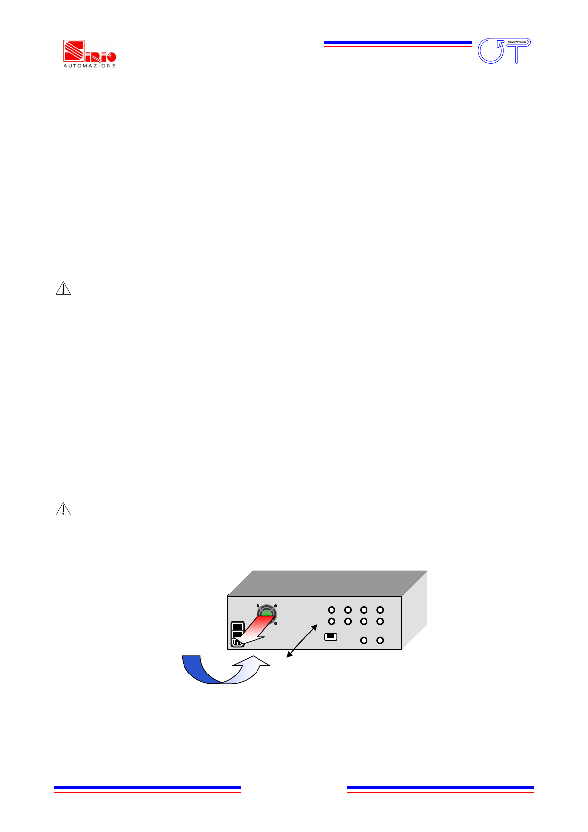
Do not obstruct the grid on the rear panel (FIG. 4).
REMARK: blocking the airflow can cause overheating and device breakdown. Ensure that the fan can
rotate freely and that nothing obstructs or blocks it.
FIG. 4 Airflow and minimum required space behind the device
Hot air flow (fan)
Cold airflow (lower
panel slots)
> 8 cm

EMG-USB User manual v.1.42
pag. 19
USB connector
Connect the PC by means of a standard A-B USB cable to this connector.
AUX IN connectors
These BNC type connectors can be used to acquire external amplified signals, in the range ± 5 V,
together with the EMG signals. The eight auxiliary inputs work also without any EMG input and the
EMG-USB can be used as an eight channels USB acquisition board with sampling frequency of
2048 Hz.
The signals at the AUX IN inputs can be assigned to any channel of the 128 available. To set the
position of the AUX IN input and acquire the signals, refer to the
Acquisition Software
user manual
version 1.80 or greater, in the “Setup Editor” chapter.
BLANKING INPUT connector
This BNC type connector is used to connect the electromyograph with a compatible neuromuscular
stimulator, to allow EMG signal acquisition during electrically elicited contractions.
This input works with digital TTL compatible signals (0÷5V), coming from the stimulator that
drives the internal blanking circuitry. When the BLANKING signal is active (5V), the amplifier
stages are inhibited to prevent saturation caused by the stimulation pulse.
TRIGGER INPUT connector
The function provided from this BNC type connector depends on the version of the software used
to acquire data.
If a version of
Acquisition Software
earlier than version 1.92 is used the TRIGGER INPUT can be
used to connect the electromyograph with a compatible neuromuscular stimulator, to allow signal
acquisition during electrically elicited contractions. This input works with digital TTL compatible
signals (0÷5V), generated by the stimulator, that is sent to the internal acquisition board to reset
the sampling process. An high level at this input reset the sampling process and the signals
acquired can be perfectly aligned with the stimulation pulse removing the jitter effect.
When using an
Acquisition Software
version equal to or greater than 1.92 the TRIGGER INPUT
behave as a data transfer enable between the EMG-USB and the PC. When the signal is a logic 0
the data transfer is disabled. This feature can be used to synchronize the acquisition start with an
external event. If the input is leaved unconnected the data transfer is always enabled.
EMG-USB User manual v.1.42
pag. 20
8. USE OF THE ELECTROMYOGRAPH
ELECTROMYOGRAPH SETUP
Before performing any measure it is necessary to set up all the instrumentation; this operation has
to be done keeping the equipment turned off. Be careful to connect all the cables properly to the
respective plugs and sockets.
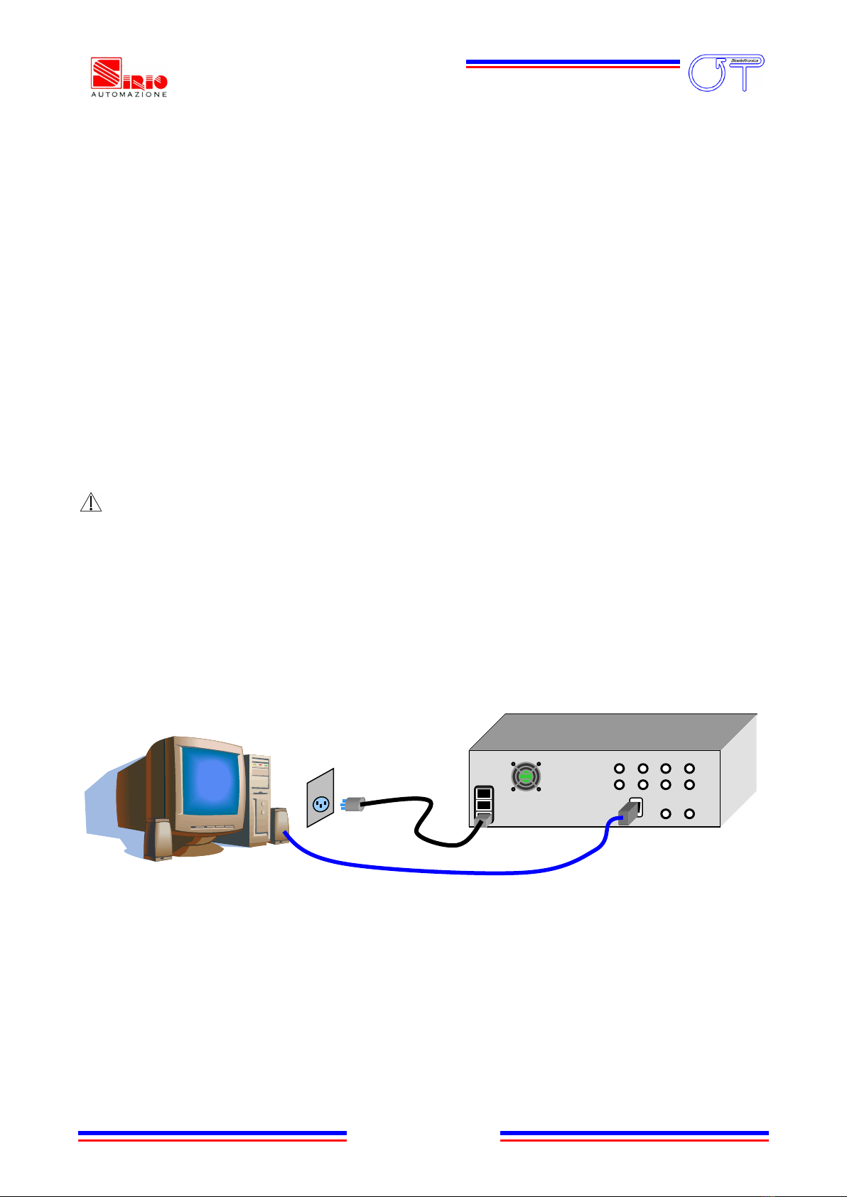
To set up correctly the electromyograph follow the instructions hereinafter (FIG. 5):
Make sure that the PC used with the electromyograph is turned off.
Make sure that the EMG-USB power on switch is set in “O” position.
Connect the USB port, placed on the EMG-USB rear panel, to one of the PC USB port by means
of an A-B USB cable.
Connect the EMG-USB power supply connector, placed on the rear panel, to a 90÷260 VAC,
50÷60 Hz power line supply voltage using the provided cable.
DANGER: the use of extension lead, multiple sockets or adapters can deteriorate the device
performances. Connection to sockets lacking in the ground conductor (“earth” conductor) or with a bad
quality of this connection can deteriorate the device performances and cause a potential risk for patient
and operator.
Turn on the PC (desktop computer or notebook).
Install the acquisition software following the instructions reported on the respective user
manual.
FIG. 5: Standard set up of the electromyograph
Computer with a free
USB port
EMG-USB Electromyograph
Type A-B USB cable
Power supply
cable
Power line
socket
Table of contents


